Both lightweight, compact airborne laser scanners are easily installed on various UAV platforms or small survey aircraft and helicopters. They are adapted to high-density point corridor mapping applications, day or night, under leaf-on and leaf-off conditions or with dense vegetation to provide reliable results.
“Nowadays, it is critical to obtain the highest data quality for the majority of aerial survey projects,” said Andrei Gorb, product manager of CHC Navigation’s Mapping and Geospatial Division.
Combining with industrial-grade GNSS receivers and high-precision inertial measurement units (IMUs), the AA1400 and AA2400 provide 2 to 5 cm survey-grade accuracy. They also integrate Riegl’s VUX lidars with waveform-lidar technology, allowing echo digitization and online waveform processing.
“Multi-target resolution is the basis for penetrating even dense foliage,” Gorb said. “The continuously rotating polygonal mirror wheel enables scanning speed of up to 400 lines per second, allowing for effective coverage of large areas when used from fast drones or aircraft.”
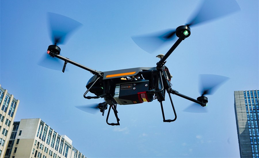
The BB4 UAV equipped with the AA2400 scanner for the city mapping task. (Photo: CHCNAV)
Their built-in premium Riegl VUX-120 and VUX-240 lidar sensors feature a high-speed data acquisition rate of up to 1.8 MHz and a scan speed up to 400 lines per second. This provides a linear accuracy of 1cm to 2 cm on long-range scanning, suitable for fixed-wing UAV corridor mapping.
CHCNAV offers several external cameras for add-ons to the AlphaAir. Setups can include nadir or nadir and oblique cameras from Sony or PhaseOne. By obtaining high-resolution geo-referenced and oblique imagery, more applications can be supported, increasing the return on investment for the client.
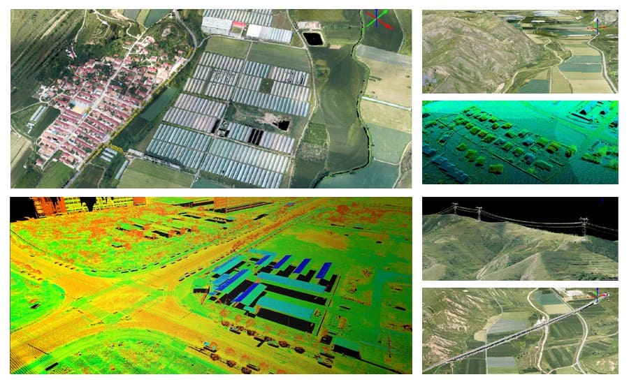
The scanning results of the AA1400 and 2400 lidar series. (Photo: CHCNAV)
The one-click connection of the AlphaPort to the power source and camera makes the installation of the AA1400 and AA2400 quick and easy, eliminating the need for additional accessories and time for camera calibration. The AA1400 and AA2400 reduce the risk of cable damage caused by aircraft vibration and acceleration during takeoff and landing.
CHCNAV provides a full range of solutions that allows a complete lidar solution to be added to the users’ geomatic services. The software suite includes CoCapture UAV field application for fully automated reality capture and real-time mission tracking, and the CoPre desktop software for semi-automated point cloud processing.
The AA1400 and AA2400 lidar series solutions are available worldwide today through the CHCNAV distribution network.
OxTS Georeferencer 2.0 is now available, introducing several key improvements, particularly for professional lidar surveyors.
Version 1, introduced almost two years ago, has since been upgraded with integration of 30 new lidar sensors, as well as providing multiple user-experience enhancements.
Surveyors can use Georeferenceer alongside any OxTS inertial navigation system (INS) to quickly and easily georeference lidar data from multiple sensors to create precise 3D point clouds.
Version 2.0 highlights
Global coordinates. OxTS Georeferencer 2.0 users can now process data in a range of coordinate systems. These include local coordinates, ECEF and LLA (latitude, longitude and altitude).
New processing options. Users can maximize the usability of their point clouds and minimize data size through a range of processing options, including:
filter points by position uncertainty keeping every point within a specified accuracy
maximize the accuracy of the data while minimizing data size with a Voxel sampling algorithm
filter points by intensity, azimuth and elevation angle of the lidar
ilter points by speed and range from a vehicle.
Improvements in map file creation. OxTS Georeferencer 2.0 can add the direction from which each point is surveyed into the point cloud, allowing mesh surfaces to be easily reconstructed.
Furthermore, OxTS Georeferencer 2.0 gives surveyors the ability to add point-normal information into the point cloud and view the vehicle trajectory as a point cloud.
Processing advances. Users benefit from better performance due to revisions of the OxTS Georeferencer processing algorithms. With version 2.0, users can process point clouds faster than before and take advantage of improved precision and consistency of the boresight calibration feature, which now utilizes target dimensions.
RedTail Lidar Systems has delivered six lidar systems to the 707th Ordnance Company stationed at Joint Base Lewis-McChord. The systems will provide explosive ordnance disposal (EOD) technicians an opportunity to assess how lidar can be used to enhance their operations.
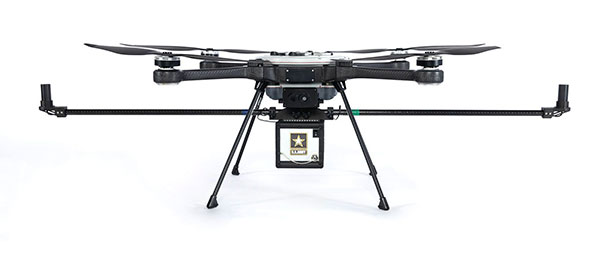
The RedTail Lidar Systems RTL-450 was integrated onto the Teledyne FLIR SkyRaider unmanned aerial system (UAS) to address a broad range of the EOD community’s 3D mapping needs. Captain William R. Hartman, the commander of the 707th EOD Company, stated that the highlight of the testing was using the lidar system to map terrain.
The RTL-450 also can be used to calculate crater volumes from improvised explosive device (IED) blasts, perform route planning for unmanned ground vehicles, aid in mission planning, and conduct surveillance. The 3D point clouds generated allow operating areas to be viewed from any perspective using the rotation and zoom capabilities provided within the viewer software.
The underlying lidar technology used in the RTL-450 was licensed from the Army Research Laboratory (ARL). The micro-electromechanical (MEMS) mirror-based design provides enhanced 3D imagery suitable for applications where artificial intelligence and machine learning (AI/ML) algorithms can be used for target detection and classification, because of the high point density of the point clouds.
The system can operate in either a raster scan mode for surveillance missions or a side-to-side line scan mode for area mapping while the UAS is flying. The intuitive command and control, high brightness display integrated into the ground control station (GCS), and real-time 3D map generation allows operators to begin mission planning and analysis even before the mapping or surveillance missions are completed.
“Delivering these six lidar systems to EOD technicians for test and evaluation is a significant step forward in using MEMS mirror-based lidar technology to address a broad range of Department of Defense 3D mapping needs,” said said Brad DeRoos, president and CEO of RedTail Lidar Systems. In addition, this delivery represents a true success story in transitioning a technology out of a Department of Defense laboratory and back into the hands of military operators.”
Oxford Technical Solutions has released the xNAV650, the latest in its line of inertial navigation systems (INS), suitable for use on drones.
INS provide surveyors with absolute position, timing and inertial measurements (heading and pitch/roll) that they can integrate into their survey projects. The measurements, when combined with data from other devices (such as lidar sensors and cameras), can greatly enhance the surveying process, leading to a greater return on investment, according to the company.
The xNAV650 is OxTS’ smallest, lightest and most affordable INS to date. It combines 20 years of navigation experience with the latest micro-electromechanical (MEMS) inertial measurement unit (IMU) technology and survey-grade GNSS receivers.
UAV Guidance
The xNAV650 provides highly accurate and reliable measurements – even when payload size and weight are imperative to consider, including for use with unmanned aerial vehicles (UAVs). It measures 77 x 63 x 24 mm and weighs 130 grams.
The xNAV650 INS is suitable for a wide range of UAV data-collection applications, including surveys of bridges, buildings, forests and rail; coastal monitoring; map creation and pipeline exploration.
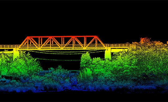
OxTS’ partner Dronezone used the xNAV650 INS and a Velodyne VLP-16 lidar on a drone to conduct a scan of an aging bridge to look for structural and potential hazards from overgrown foliage.
By fusing the timing, position and inertial data from the INS with the raw data of the Velodyne VLP-16 (using OxTS’ lidar georeferencing software OxTS Georeferencer), the surveyor was able to produce a highly accurate 3D point cloud of the bridge. Fusing the position and inertial data from the xNAV650 INS with the Velodyne VLP-16 lidar data provides a high level of clarit, which can be seen in the foliage, electricity lines and side of the bridge.
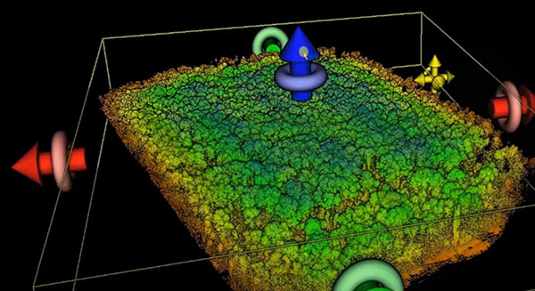
The resulting point cloud has enabled the engineers to easily and accurately pinpoint areas of the bridge that need closer attention.
Side view point cloud of bridge. Data collected using and OxTS xNAV650 INS and Velodyne VLP-16 lidar. Data processed using OxTS Georeferencer. (Image: OxTS)
NAVsuite Software
Data from OxTS INS can be fused with the data from almost any lidar sensor. Using OxTS Georeferencer software, point clouds can be georeferences from lidar units specifically from Velodyne, Hesai and Ouster sensors. Work is underway to integrate new lidar sensors from an even wider range of manufacturers into OxTS Georeferencer – allowing OxTS INS users to build a full navigation solution where much of the integration work is already taken care of.
OxTS NAVsuite software is included with all OxTS INS. The full range of software tools allows users of OxTS’ devices to configure and post-process data with ease.
Other optional software features are also available, including Precision Time Protocol (PTP) and GX/IX tight-coupling technology. PTP allows for a much simpler lidar survey set-up over ethernet while simultaneously stamping out time-drift by utilizing the high-quality INS clock source – GNSS. GX/IX tight-coupling technology, OxTS’ own proprietary navigation engine, ensures that users of OxTS Inertial Navigation Systems receive the most accurate measurements possible even in tough GNSS conditions.
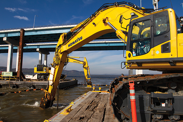
Trimble hardware and software tracked the position and motions of the machines and displayed to the operators the position of their tools underwater. (Photo: Trimble)
A new, twin cable-stayed bridge was built a few yards north of the original bridge by Tappan Zee Constructors LLC (TZC), a consortium of firms. The Left Coast Lifter — a huge crane on a barge previously used to replace a span of the San Francisco-Oakland Bay Bridge — was used to install groups of pre-assembled girders one full span at a time. Construction of the new bridge and demolition of the old one overlapped, with the entire project completed in May 2019.
The project was huge, complex and on an accelerated schedule. “Challenges included the size of the bridge, the river’s current, tidal variations, the water’s turbidity and strong winds,” recalled Jonathan White, product manager for Trimble Civil Construction Field Solutions, Marine. Conditions were particularly challenging for bathymetric data collection before and during the project. “The low visibility in the water made it a prime situation for sonar technology to play a major role.”
A licensed surveyor conducted a pre-dredge bathymetric survey, which was loaded into the construction software as a baseline. Trimble hardware, software and technical advice supported the demolition of the old bridge.
“As they were beating down the bridge with the jack hammers and trying to pick up the rubble from the river with the cranes, the main challenge was to keep the 11 machines that they had updated in real time with the most accurate 3D data, so that they could keep working,” explained Nathan Keys, a geospatial engineer at Measutronics, a Trimble dealership and project lead for the Tappan Zee Bridge project.
Rather than mount a sonar to the front of each construction barge, they used a single survey vessel to serve the machines (eight excavators and three clamshell cranes) with real-time data, using networked connections to update one machine at a time.
Whenever a crane operator thought he was done in an area — the machine guidance display in his cab told him that he had achieved the design depth — the survey boat would verify that, and either give the operator the go-ahead to continue working or point out any spots that were still too high or too low. “That way, they would avoid having to return to an area, which costs time and money,” Keys said.
Trimble equipment provided the positioning of the machines, tracked their motions, and visualized them, enabling the operators to “see” underwater where their bucket, grapple tool, clamshell, or other tool was operating. Trimble supported its dealer and the consortium that was executing the project, White said. “Measutronics is very well versed in the capabilities of Trimble equipment and, more broadly, marine construction workflows generally. If a piece of their equipment went down, we could swap something out and provide them with any support that they needed, and expedite that support because we knew how crucial it was with them being in the field pretty much 24/7.”
Marine excavation. The survey vessel was equipped with a Teledyne RESON T-20 multibeam sonar and a Trimble Applanix POS MV WaveMaster for motion and position. “The eight excavators were equipped with a Trimble marine excavator guidance package, which includes a GPS receiver and angle sensors working together to give guidance to the tool, whether it is a jack hammer, a bucket or whatever,” said Keys. “They also had three clamshell cranes with rotational encoders on the wire-out drums, to keep track of the bucket’s vertical. The central piece to all this is the Trimble Marine Construction software, which takes in the data from all the sensors, including the sonar, in real time and updates the display in the cabin.”
To install its sensors on machines, Trimble provides flexible aftermarket kits that come with weld plates. “We just point out to the customer where to weld the plates, then we will put the sensors on, run the cables to the cab, and do all the wire runs,” Keys explains. “It does not matter whether it is a Caterpillar or a Kobelco or whatever. They are aftermarket systems, so they can go on pretty much any machine.”
This project, Keys clarified, involved only machine guidance, not automation. “We were not using any of the machines’ own sensors. We showed them where they were and then the operator would have to control it.”
Trimble provided precise position and heading, White said. “Through a very accurate measure of where each of these sensors is installed relative to the phase center of the GPS antenna, we can determine how the machine is moving and measure that movement, so that we know exactly where the tool is relative to the position that we are getting from our satellite trilateration. It is not like the guy is sitting in the seat drinking a cup of coffee while the machine parallel parks itself. However, he is receiving a lot of information from all those sensors as to his tool’s position relative to that GPS location.”
Keys said the machines constantly log the data and their movements while they are running. “We can go back into those log files and pull out whatever we want,” he said. “On the survey side, when they do a scan or a survey of an area, that data is captured as a 3D point cloud of what the bottom looks like, which you can import into any software to visualize and quantify the riverbed and the rubble.
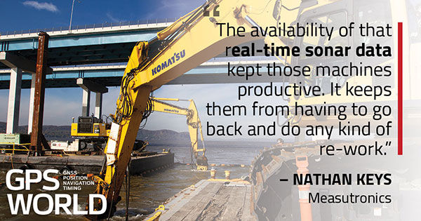
“The availability of that real-time sonar data kept those machines productive,” Keys said. “It keeps them from having to go back and do any kind of re-work.”
White said the technology is getting more affordable and user-friendly. “That is leading us, as a manufacturer, to look for ways to help further bring it into our standardized workflows. We have been working with Teledyne on those objectives.”
Trimble is also keen to advance the networking component, specifically to the marine sector, White added. “It is relatively new to marine construction projects. The ability to have a sonar vessel speaking to a machine, and all the machines to speak to each other, and to share a survey file is a very important objective for us.”
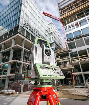
The new version of all-in-one MultiStation addresses a wide range of needs. (Photo: Leica Geosystems)
The new Nova MS60 MultiStation combines upgraded, faster 3D laser-scanning capabilities, GNSS connectivity and digital imaging with a high-end total station. According to Leica Geosystems, part of Hexagon, the multi-station brings sensor fusion to the “next level.”
The MS60 features several laser scanning updates, including an fast scanning speed of up to 30,000 points per second, optimized scan area definitions, adapted scan managements, and an improved scanning path for zenith scans.
It is also equipped with the unique AutoHeight feature, enabling users to save time by automatically measuring the instrument’s height with a simple button press. Measurement professionals can make decisions directly in the field, performing point-cloud analysis such as flatness analysis and as-built checks in the Inspect Surface app of the MS60.
“Scan data combined with traditionally measured points, whether it’s from the total stations or the GPS receivers, is one of those immediate deliverables that help our clients see what we’re doing. With the scan data of the Leica Nova MS60 MultiStation, we can graphically show — the same day it is collecting — the locations in the field to any person,” said Donald Smith, senior land surveyor and principal at BL Companies. “When you deliver on time and provide customers with a deliverable they can see, you’ve just got yourself a recurring client.”
The MS60 speeds up workflows by combining technologies in this all-in-one instrument. The MultiStation total station offers advanced imaging, scanning capabilities and GNSS connectivity. With Leica Captivate field software, all measurement and scanning data can be visualized in 3D for quality and completeness checks.
MS60 users can seamlessly transfer all data into Leica Infinity software to manage, process, analyze and perform a quality check. The MultiStation helps users deliver projects on time, save money and have high flexibility in the field.
“The MS60 merges data in a multi-level process — total station measurements are complemented by 3D point clouds, which are automatically registered and coloured by the image information. All data perfectly fits within the same coordinate system, globally referenced by GNSS measurements or by measuring known points,” said Falko Henning, senior product manager at Leica Geosystems.
“Unlike other measurement devices, the MS60 offers familiar total station capabilities and scanning functionality to fulfil job requirements on site.” Henning said. “The operator can use the red laser pointer to perform reflectorless measurements for direct remedial work on-site or stakeout points and use the field controller even while a scan is performed.”
Trimble Clarity features cloud integration and support for 3D point cloud, imagery and mesh model formats. (Photo: Trimble)
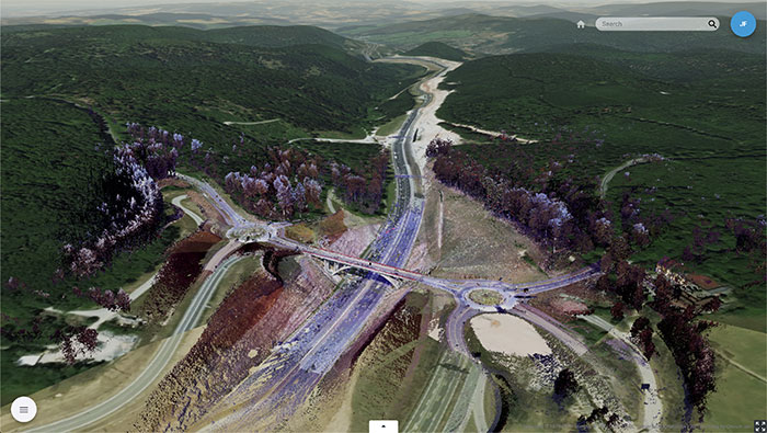
Trimble’s browser-based viewer Trimble Clarity is now offered as a stand-alone web application, designed to simplify the visualization and navigation of 3D data.
According to the company, Trimble Clarity enables geospatial professionals to view, use and share 3D point cloud data, models and meshes with engineers, architects, city planners and other project stakeholders via a web browser, which can be viewed on desktop and mobile devices.
The Trimble Clarity web application allows users to generate private or public web links to share project information and 3D data. It also supports data from Trimble products, such as the Trimble SX10 scanning total station, Trimble TX Series 3D scanners and Trimble MX9 mobile mapping system, as well as data from non-Trimble sources.
In addition, with the upcoming version of Trimble Business Center office software 5.20, users can publish their 3D data directly into Trimble Clarity, creating a seamless integration and workflow between both platforms. Trimble Clarity provides a visual directory, which allows users to view 3D data as location-based projects.
Trimble Clarity also features cloud integration and support for 3D point cloud, imagery and mesh model formats.
“Trimble Clarity enables users to easily share and view rich 3D point clouds without having to transfer, copy or mail large data sets,” said Tim Lemmon, marketing director of Trimble Geospatial. “By leveraging an intuitive, browser-based experience, stakeholders can easily visualize and understand project data, enabling greater collaboration and informed decision making.”
NavVis, a provider of indoor spatial intelligence technology, can now automatically convert E57 point cloud files into interactive, realistic 360-degree walkthroughs, following the latest software upgrade to IndoorViewer.
Visitors to Intergeo 2018 can demo the new NavVis IndoorViewer release as well as the NavVis M6 indoor mobile mapping system by visiting NavVis in Hall 12.1 at booth 12.1D.086.
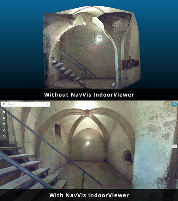
Image: NavVis
NavVis IndoorViewer is a web-based application that displays realistic digital twins using 360-degree panoramic images, point clouds and maps generated by 3D scanning devices. Users can move around digital twins of scanned spaces as if they are on site and use the interactive functionality to add, search for and route to geotagged information and take accurate measurements.
The intuitive user interface and functionality has made NavVis IndoorViewer a valuable deliverable for laser scanning professionals who want to extend the use of point clouds beyond BIM models and building plans to a wider range of building stakeholders who would also benefit from 3D scan data.
This is particularly relevant for stakeholders working on complex projects or properties, such as manufacturing facilities and construction sites, where IndoorViewer enables remote access to the site and is used as a platform for collaboration and exchanging information, the company said.
“IndoorViewer was originally developed to display the data captured by our indoor mobile mapping system in a way that is accessible to every user,” said Felix Reinshagen, NavVis CEO. “In recent years, we have seen that making scan data available to every building stakeholder is fulfilling an unmet need. Many of our partners using a NavVis indoor mobile mapping system for conventional scanning projects are offering IndoorViewer as an additional deliverable to increase the number of stakeholders who can make use of this data.”
“To meet the growing demand for extending the use of valuable 3D scan data, we developed a feature that automatically renders 360-degree immersive images from structured E57 point cloud files. The latest software release brings the full functionality of IndoorViewer to E57 point cloud files and therefore marks an important step towards our goal of making scan data meaningful for every building stakeholder.”
NavVis IndoorViewer currently supports third party point cloud files in most standard formats. However, a key component of the immersive experience that NavVis IndoorViewer provides is the 360-degree panoramic images.
The new IndoorViewer feature bridges this gap for structured E57 files by automatically rendering 360-degree immersive imagery from E57 point cloud files. This means data collected by terrestrial laser scanners can now also be used to create realistic, immersive 360-degree walkthroughs that can be published and shared online without the need to download or install software.
The E57 panorama extractor is available as part of a free software upgrade to IndoorViewer subscribers.
DT Research has released the DT301T rugged RTK tablet (DT301T-RTK), a lightweight military-grade tablet purpose-built for GIS mapping applications. It features real-time kinematic (RTK) satellite navigation to enhance the precision of GNSS position data.
The tablet enables 3D point cloud creation with centimeter-level accuracy, meeting the high standards required for scientific-grade evidence in court.
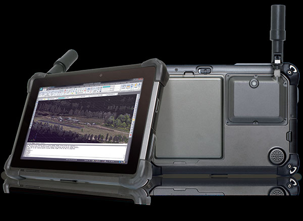
The DT301T-RTK is a rugged tablet with scientific-grade GNSS. (Photo: DT Research)
The DT301T Rugged RTK tablet is military-grade with an IP65 rating. Because it’s lightweight, the DT301T can be used in the field, office and vehicles, the company said.
A dual-frequency GNSS module is built into the tablet, which uses real-time reference points within 1–2-centimeter accuracy to position 3D point clouds created from aerial photogrammetry, using GPS, GLONASS and Galileo receivers. Users can measure with the RTK GNSS positioning directly using a foldable antenna or connect to an external antenna for more robust receiving and survey-grade precision.
“We’ve seen a dramatic uptick in the need for rugged tablets to be purpose-built for a range of mapping uses across industries,” said Daw Tsai Sc.D., president of DT Research. “In designing the DT301T with RTK satellite navigation, we also took into consideration the other features and capabilities necessary within a rugged tablet to quickly and easily conduct forensic mapping, land surveying, e-construction, building information modeling (BIM) and other mapping scenarios.”
The DT301T is compatible with existing GIS software for mapping applications and brings together the advanced workflow for GIS data capture, accurate positioning and data transmitting.
Uses
According to DT Research, the tablet can be used in a variety of scenarios.
Forensic mapping. Public safety teams, investigators and crash reconstructionists can use the DT301T Rugged RTK tablet to accurately collect measurements that are scientifically defensible by using the real-time centimeter reference points to position 3D point clouds created from aerial photogrammetry or take stand-alone measurements.
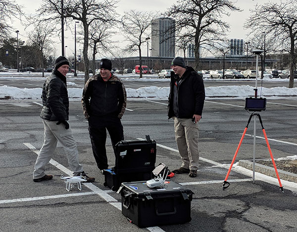
DT301T-RTK tablet during forensic mapping training. (Photo: DT Research)
The results will have the precision necessary to stand up as evidence in court, said Andrew S. Klane, a former Massachusetts State Police Lieutenant who teaches Forensic Mapping and is now the chief operating officer at Forensic Mapping Solutions Inc.
“As more drones are being used for mapping, there is a growing need for ground-control positioning devices,” Klane said. “By using a DT301T Rugged RTK Tablet in combination with a drone, users can more quickly and cost-effectively create a 3D model to deliver an accurate representation of the scene with scientific-grade tolerance that will hold up in a court of law.”
It could also help clear crash scenes faster, restoring the normal flow of traffic on congested roadways, reducing secondary crashes and lowering the chance of first responders and other workers getting hurt while clearing the scene.
Land surveying. Surveyors can use the DT301T tablet to measure the altitudes, angles and distances on the land surface so that they can be accurately plotted on a map to determine property boundaries, construction layout and mapmaking.
E-construction. Construction workers can manage the collection, review, approval and distribution of highway construction contract documents in a paperless environment using the DT301 tablet.
Building information modeling (BIM). Architecture, engineering, and construction (AEC) professionals can use the tablet to create 3D models to efficiently plan, design, construct and manage buildings and infrastructure.
FEATURES
The DT301T Rugged RTK tablet has been purpose-built for precision mapping in a variety of environments and includes the following features and capabilities:
Dual-frequency GNSS module: GNSS L1 and L2 RTK that receives GPS, GLONASS and Galileo signals up to 372 channels with RMS 10 mm + 1 ppm accuracy.
High-performance CPU and Windows OS: Intel 6th-generation core i5 or i7 processor with Microsoft Windows 7 Professional or Windows 10 IoT Enterprise. Units come with either 8 GB or 16 GB of RAM.
Sunlight-readable display: A 10.1 inch LED-backlight, sunlight-readable screen with capacitive touch and 1920 x 1200 resolution.
Wireless connectivity: Long-range Class 1 Bluetooth powers connectivity up to 1,000 feet and 4G mobile broadband for LTE, HESPA+, GMS/GPRS/EDGE, EV-DO, Rev A and 1xRTT.
Storage: For field data collecting, the tablet can store up to 1 terabyte of data.
Military standards: The tablet is fully ruggedized to meet the highest durability standards with an IP65 rating, MIL-STD-810G for vibration and shock resistance, and MIL-STD-461F for EMI and EMC tolerance.
Battery pack: High-capacity hot-swappable battery pack delivers 60 or 90 watts for up to 15 hours of continuous mobile communications.
Accessories: Those available include external antennas, pole mount cradles, detachable keyboards, battery charging kits and digital pens.
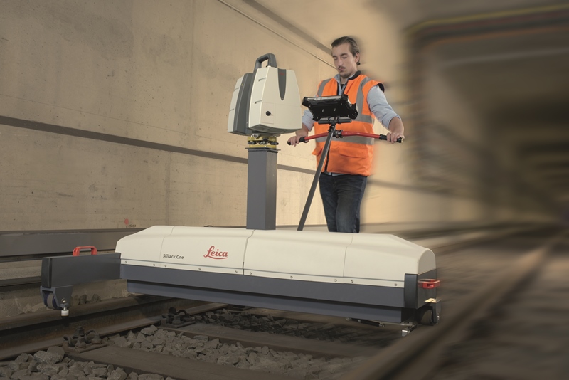
Leica Geosystems has released SiTrack:One, a highly accurate rail track maintenance and refurbishment system incorporating the Leica ScanStation P40 to generate 3D point clouds. SiTrack:One by Leica Geosystems ensures complete coverage of an entire rail infrastructure surface without the need to receive GNSS signals for position information, the company said.
With a new mounting design, the total solution for rail maintenance and refurbishment produces synchronized engineering, survey-grade 3D point clouds for accurate as-built drawings. The Leica ScanStation P40 can either be mounted vertically in the centre of the rails or inverted directly over the rail track. Rail bridge sleeper replacements can be measured quickly generating a numbered as-built replacement plan for each individual sleeper on a rail bridge.
The sophisticated system is equipped with two powerful distance measurement instrument (DMI) or odometers that provide accurate positioning in GNSS-denied areas, such as underground railway tunnels or underground subway networks. The system’s on-site calibration process guarantees permanent alignment of the relative position between the sensors and its onboard inertial measurement unit, guaranteeing position accuracy.
The German engineering firm Vermessungsbüro Riemenschneider GbR was the first to use the SiTrack:One by Leica Geosystems. When converting existing railway tracks in the course of track maintenance for the Deutsche Bahn AG, the firm required complete, accurate and consistent information on existing tracks, clear structure gauge, route topography and civil engineering works. With the SiTrack:One, Vermessungsbüro Riemenschneider GbR experienced significant workflow gains by leveraging the highly accurate point clouds directly into the engineering process.
“The SiTrack:One by Leica Geosystems guaranteed the complete survey of railway sidings with a minimum stay of surveying personnel in the danger zone of rail transport,” said Dipl.-Ing. Andreas Riemenschneider, principal of Vermessungsbüro Riemenschneider. “Thus, the costs of security measures were significantly reduced. The state-of-the-art system conforms efficiently to the demands for survey, visualisation, documentation, evaluation and approval of existing and new routes, all in accordance with rail transportation guidelines.”
Developed from acquired knowledge SiTrack:One is the first solution to be released under Leica Geosystems from the acquisition of the former Technet-Rail 2010 GmbH. Leica Geosystems acquired the previous firm’s specialised knowledge of geospatial big data for rail transportation networks in May to increase its mobile mapping offerings for the rail industry.
“One of our goals in obtaining this specific know-how was to provide users with a dedicated tool for passenger rail networks monitoring and maintenance, and with the development of SiTrack:One, we are taking the first step on this roadmap,” said Stuart Woods, Leica Geosystems Geospatial Solutions Division vice-president. “Professionals can now trust their measurements on rail are accurate even in the most difficult conditions.”
SiTrack:One by Leica Geosystems includes software enabling data synchronization, post-processing and feature extraction. This solution is part of the SiRail Suite, which includes the SiRailScan and SiRailManager software solutions.
SiRailScan allows for a complete extraction of the railway network with engineering accuracy level, while SiRailManager, the database management tool, creates a holistic view of an operator’s railway network from point cloud to geometry and signal layers. The combination of these solutions form the SiControl platform, which conforms to the requirements of the European Train Control System and produces complaint rail xml outputs for full train feedback control.