Tbe company has received Global Certification Forum validation of 5G LBS Assisted-Galileo test case
Keysight Technologies Inc. has gained Global Certification Forum (GCF) validation of a 5G location-based services (LBS) assisted-Galileo (A-Galileo) test case by combining 5G new radio (NR) and GNSS technology.
The achievement will accelerate implementation of LBS in smartphones by enabling mobile phone vendors to verify that designs comply to the latest 3GPP specifications that support accurate location positioning in a wide range of sectors.
Sectors include healthcare, road and aerial transportation, emergency and rescue services, public safety, and homeland security. Highly precise positioning services also enable mobile operators to deliver personalized services supporting entertainment, hospitality and retail applications.
LBS leverages different technologies, including GNSS, beamforming and round-trip time to geographically locate a user. LBS test cases allow users to verify sensitivity, accuracy and dynamic range in mobile phones that leverage GNSS constellations to identify precise geographic location.
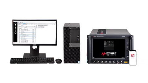
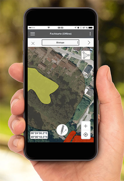
S8705A RF/RRM DVT and Conformance Toolset. (Photo: Keysight)
GCF conformance agreement group meeting #72, held Oct. 21, confirmed the validation of the first 5G LBS A-Galileo test case, which was supported by Keysight’s S8705A RF/RRM DVT and Conformance Toolset. The toolset provides access to a wide range of radio frequency, radio resource management, and development validation test cases used to verify 5G NR designs in both non-standalone and standalone deployment modes.
The S8705A toolset uses the E7515B UXM 5G Wireless Test Platform, a compact signaling test platform with multi-format stack support, rich processing power and abundant RF resources for emulating various mobility scenarios in a 5G network as well as a recommended GNSS emulator to deliver the LBS test case.
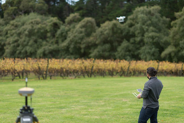
Trials in Australia are proving 5G LPP can support new positioning services. (Photo: Dan Woodrow, FrontierSI)
Several companies are joining to demonstrate 5G LTE Positioning Protocol (LPP) capabilities in field trials. The trials are part of the 5G Positioning Testbed funded under the Australian 5G Innovation Initiative.
Technology partners include GMV, FrontierSI, Ericsson and Optus, who are joining with industry demonstration partners Kondinin Group, Platfarm (a precision agriculture company) and Position Partners.
The results achieved by the project are considered a key step forward for the use of 5G technology for high-accuracy positioning. The testbed demonstrated each of the high accuracy GNSS-based LPP working modes, including Observation Space Representation (OSR), State Space Representation (SSR), and SSR with atmospheric corrections, integrated directly with user equipment supplied by demonstration partners to examine a variety of real-world applications. The field trials demonstrated that the solution can reach centimeter-level accuracy with fast convergence times using a commercial off-the-shelf receiver and antenna hardware.
GNSS precise positioning is the most common technology for calculating an absolute positioning solution at the user level. For uses requiring centimeter-level accuracy, it is often required to provide GNSS corrections to reduce errors.
Distribution of GNSS corrections is based on either the broadcast of precise point positioning (PPP) corrections through GEO satellites over the L-band, or the point-to-point transmission of real-time kinematic (RTK) corrections using NTRIP through the internet.
Both options have their drawbacks: GEO satellite broadcast requires complex ground infrastructure and can be expensive to maintain, while NTRIP distribution has poor scalability due to the point-to-point connections required for every user.
3GPP (3rd Generation Partnership Project) — the standards organization focusing on 5G LPP — recently introduced the support of OSR corrections for RTK users in Release 15, and the support of SSR plus atmospheric corrections for PPP/PPP-RTK users in Release 16.
Support for these two approaches to high-accuracy GNSS positioning have increased interest in 5G LPP as a potential alternative to existing correction services. Service providers and positioning consumers can now consider the use of 5G LPP as a supporting technology in the provision of new positioning services directly through mobile networks.
The 5G Positioning Testbed has achieved end-to-end demonstrations of high-accuracy positioning solutions using GMV’s Corrections Service and Positioning Engine, delivered through the Optus 5G network using Ericsson network technology, to user equipment designed and operated by FrontierSI.
Field trials conducted in Australia involved real-world scenarios across three areas: precision agriculture, drone operation and augmented reality.
Integrated solutions address GNSS test requirements defined by 3GPP and major U.S. carriers
Orolia and Keysight Technologies Inc. have joined forces to advance 5G services by addressing GNSS test requirements defined by 3GPP and major U.S. carriers.
Working with Orolia allows Keysight to extend its 5G device test solution portfolio with advanced GNSS simulation capabilities. As a result, existing users of Keysight’s 5G device test solutions can easily address GNSS-related 3GPP protocol conformance and carrier acceptance test requirements by upgrading the software in Keysight’s E7515B UXM 5G Wireless Test Platform and combining it with Orolia’s GSG-8 simulator.
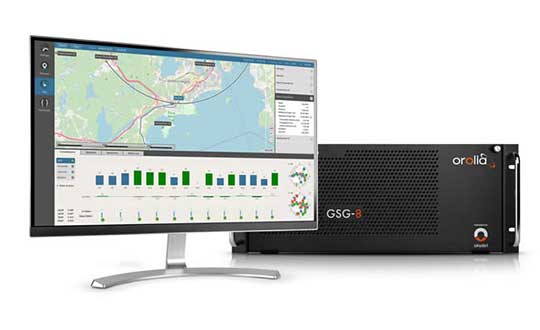
Skydel GSG-8 (Photo: Orolia)
The efforts of Keysight and Orolia will enable chipset and device makers to verify functionality to accurately position mobile phone users within a geographic area.
“Working with Orolia has enabled Keysight to deliver GNSS-based LBS test solutions for 5G protocol conformance and carrier acceptance validation,” said Muthu Kumaran, general manager of Keysight’s device validation solutions business. “Keysight’s LBS solutions also support assisted GNSS test functionality, enabling users to comprehensively address 5G new radio conformance requirements mandated by both the Global Certification Forum (GCF) and PTCRB.”
Accurate positioning is important in a wide range of sectors including healthcare, road and aerial transportation, entertainment and homeland security.
Future applications, such as drones and autonomous vehicles, will depend on highly precise positioning services for reliable navigation and safe transportation of people and goods. Mobile operators use GNSS technologies and non-GNSS technologies, such as beamforming, angle-based positioning and round-trip time to deliver personalized services and support emergency calls.
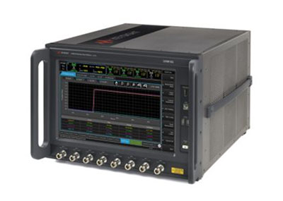
Keysight’s UXM 5G Wireless Test Platform. (Photo: Keysight Technologies)
The GSG-8 simulator, powered by the Skydel Simulation Engine, offers high performance, flexibility and an easy-to-use software-defined platform to deliver superior jamming and spoofing options that can help ensure accurate, continuous operations for critical applications during interference or signal loss. Automated and scalable, the simulator supports GPS, Galileo GLONASS and BeiDou, with upgrade paths for future constellations.
Keysight offers in-built positioning capabilities in the UXM 5G wireless test platform for non-GNSS positioning test requirements.
“We are pleased to collaborate with Keysight on developing solutions that improve PNT testing for 5G communication networks and devices,” said Lisa Perdue, Orolia’s Simulation Product Line director. “Our GSG-8 simulator, powered by Orolia’s Skydel Simulation Engine, offers ultra-high performance and unmatched flexibility. The easy-to-use software-defined platform also delivers superior jamming and spoofing options that can help ensure accurate, continuous operations for critical applications during interference or signal loss.”
Global mobile wireless standards body 3GPP has given its approval to the regional navigation system created by the Indian Space Research Organization (ISRO), known as NaVIC, reports The Times of India.
The approval was given for the system’s use in Rel-16 LTE and Rel-17 5G NR specifications, paving the way for wider commercial adoption of NaVIC and allowing it to be integrated with 4G, 5G and internet of things technology (IoT).
Once these specifications are adopted by Telecommunications Standards Development Society, India (TSDSI), IoT devices in India can make a switch from GPS to NaVIC.
Electronics companies can start designing and building integrated circuits and mass manufacture other products created to be compatible with NaVIC.
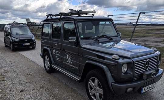
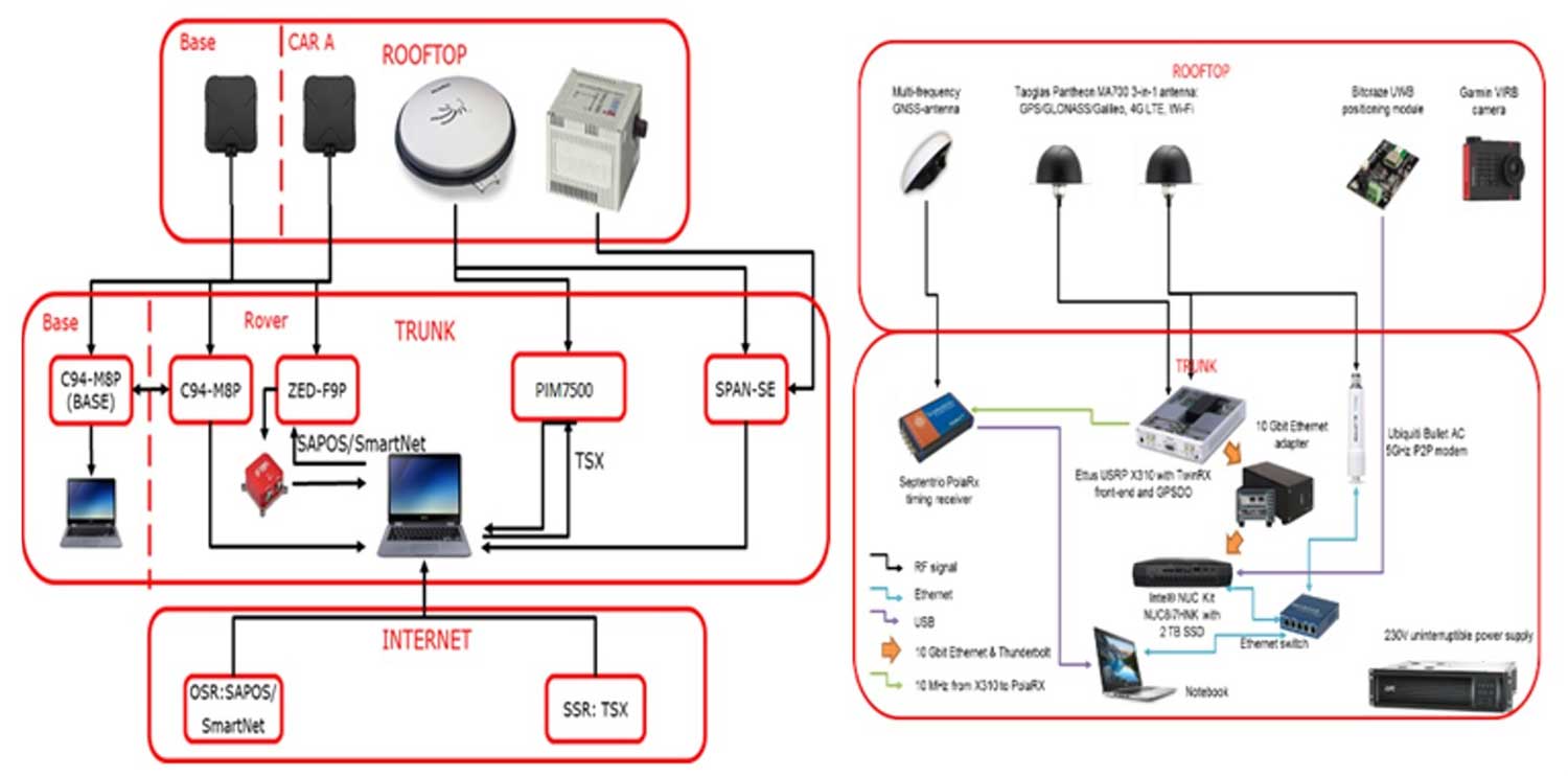
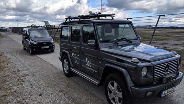
A pair of testbed vehicles went out on the road in Germany to simulate the way we are all likely to be using 5G positioning services in the future. The field test focused on assessing the performance of highly precise hybrid satellite/terrestrial positioning for autonomous vehicles, drones, smart cities and the internet of things (IoT).
The two vehicles were driven for a week around Munich and the surrounding area in a variety of environments, from the open-sky terrain surrounding the German Aerospace Center DLR’s site in Oberpfaffenhofen to the deep urban canyons of the city’s dense Maxverstadt district.
As they drove, they combined a broad range of on-board systems to measure their positions and share them with one another, performing ongoing vehicle-to-vehicle ranging to simulate future 5G operating standards.
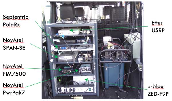
The on-board systems included multi-constellation satellite navigation (combining Europe’s Galileo, the U.S. GPS, Russian GLONASS and Chinese BeiDou), incorporating localized high-accuracy correction, and 4G Long-Term Evolution (LTE) and ultra-wideband (UWB) terrestrial wireless broadband communication.
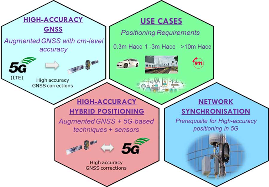
The coming of the next generation of mobile phone networks, 5G, promises much faster, more stable connectivity based on higher bandwidths and frequencies, but the ability to download a full movie in a matter of seconds is only the start. The increased capabilities will also open up a new range of services, many of them based around localization.
From smart traffic management to asset tracking to personalized drone-based delivery, our receivers’ ability to know where they are and share those positions with the wider network will be vital.
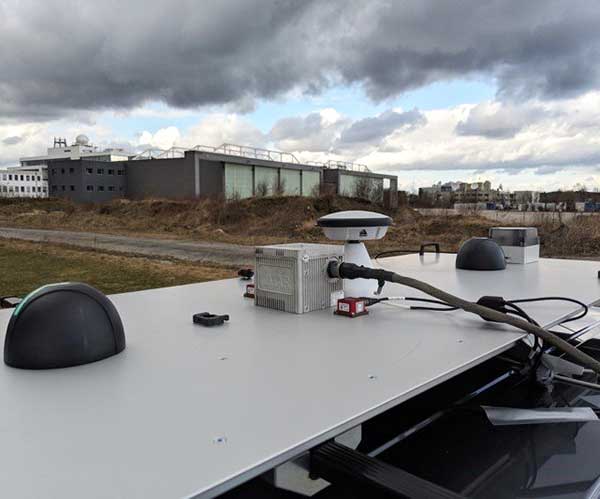
Close-up view of Car A with GNSS and LTE antennas. (Photo: ESA)
“The first step required is understanding what the upcoming disruptive applications are, and to identify the potential requirements associated with them,” said Riccardo de Gaudenzi, who leads ESA’s Electrical Department in its Directorate of Technology, Engineering and Quality.
“For these use cases, positioning and timing are key elements. Therefore positioning, navigation and timing (PNT) aspects, provided via GNSS like Galileo, the terrestrial communication infrastructure and hybridization of technologies, are extremely important.”
The testbed vehicles combined a broad range of on-board systems, including multi-constellation GNSS, incorporating localized high-accuracy correction. (Image: ESA)
Today we rely largely on satellite navigation to determine where we are. But our smartphones quietly blend satnav with other data sources to sharpen the accuracy of their results. That is why, for example, when you turn off your phone’s Wi-Fi receiver, your smartphone will warn you its mapping will become less accurate – it is also using Wi-Fi maps as a reference source.
With 5G, this trend of hybrid positioning will accelerate. Multiple GNSS constellation will be employed to increase accuracy, along with localized correction systems. In addition, the 5G cell network will provide additional corrections to enhance the GNSS localization accuracy and to complement GNSS when satellites are not visible.
This 5G “new radio” positioning accuracy will be enhanced by using steerable antennas on both the base station and the user terminal.
The testbed vehicles combined a broad range of on-board systems, incorporating localized high-accuracy correction and LTE 4G and ultra-wide-band terrestrial wireless broadband communication, to measure their positions and share them with one another and perform ongoing vehicle-to-vehicle ranging to simulate future 5G operating standards. (Image: ESA)
And because positioning performance will have to remain at the same high standard as user receivers move around — whether they be people, cars, shared bikes or drones — additional positioning solutions will also be employed, such as inertial sensors or device-to-device relative positioning.
Areas where ESA is contributing to 3GPP standardisation efforts. (Image: ESA)
Miguel Manteiga Bautista, head of ESA’s GNSS Evolution and Strategy Division in the Agency’s Directorate of Navigation, explains, “For the hybrid positioning field-tests, ESA and its partners set up a collaboration with Deutsche Telecom for use of its 4G network in Munich including relevant information for positioning, and NovAtel, who provided state-of-the-art GNSS equipment and correction services, such as the satellite-based TerraStar-X.”
ESA oversaw this initial field test campaign as part of its 5G GNSS Task Force, coordinated with the European Commission and the European GNSS Agency through the Horizon 2020 Framework Programme for Research and Innovation in Satellite Navigation.
The field test campaign was undertaken by DLR and the GMV company, with contributions by engineers from NovAtel, u-blox and Deutsche Telekom as well as ESA.
In 2016 the 5G GNSS Task Force within H2020 took the initiative to shape the support of high-accuracy positioning services in 4G and 5G networks, to contribute to the 3rd Generation Partnership Project, 3GPP, worldwide standardisation effort.
These field tests are executed within the GNSS Integration into 5G wireless networks or GINTO5G project. Undertaken through ESA’s European GNSS Evolution Programme, this project is being is executed by a consortium composed by GMV, Universitat Autonoma de Barcelona (UAB), DLR, u-blox and Telefonica I+D.
Currently, UAB is involved in the thorough processing of all the data gathered during the field test campaign, leading into models and simulation tools and possibly additional field experiments.
This pair of testbed vehicles went out on the road in Germany to simulate the way we are all likely to be using 5G positioning services in the future. (Photo: ESA)
Narrowband IoT (NB‑IoT) is a new way of communicating with the “things” in Internet of Things that was standardized by 3GPP in June 2016.
The latest mobile broadband standard, NB-IoT is aimed at devices that need to communicate small amounts of data over long periods in hard-to-reach places. It connects devices through existing GSM and LTE spectrum networks.
NB-IoT uses the 3GPP-licensed network spectrum, which is secure and free from interference, and offers low power, long range, the ability to penetrate walls and metal barriers, and support for about 50,000 devices per single cellular cell.
“Narrowband IoT will be good for connecting devices in locations where the signal distance is in kilometers and for locations in basements and underground,” said Antenova CEO Colin Newman.
“It could be the enabler for some of the IoT applications that are emerging that are not suited to the established telecoms networks, where the data throughput is quite low and infrequent.
“We see these antennas being used for smart metering, agricultural technologies, building automation and smart-city applications with lighting, waste bins and parking spaces,” Newman said.
Digicom’s narrowband IoT GPS tracker has u-blox inside.
u-blox and Digicom. Chip-maker u-blox partnered with Digicom to develop its NB-IoT products, carrying out a series of innovative and successful field trials of the new NB-IoT technology.
Digicom offers solutions for industrial markets using NB-IoT, with a focus on connectivity solutions for smart cities, smart buildings, industry 4.0 in general and the automotive industry. Digicom platforms are designed for the protection of vehicles, people and pets, offer ultra-low-power consumption and several years of operation in battery mode.
Embedded in Digicom’s products are u-blox modules such as the SARA‑N2 NB-IoT.
CEVA Dragonfly. CEVA Inc. and Hong Kong Applied Science and Technology Research Institute Company Limited (ASTRI) introduced Dragonfly NB1, a comprehensive NB-IoT solution with excellent performance and power consumption. It is easily integrated into a system on chip (SoC).
GMV Add-On for GNSS. Also, CEVA and ASTRI teamed up with GMV to offer integrated GNSS for smart devices with location tracking of logistics, assets, wearables and more.
The GNSS IP is available as an add-on software that runs on the CEVA-X1 together with NB-IoT and leverages ASTRI’s GNSS RF IP embedded in the solution.
GMV’s software IP supports all four GNSS constellations: GPS, BeiDou, GLONASS and Galileo, and allows seamless switching between constellations when required or to run multiple constellations concurrently to improve resolution and offer global asset tracking.
Antenova Latona. Antenova has developed a new NB-IoT chip antenna in the company’s lamiiANT antenna family named Latona. The antenna measures 20 x 11 x 1.6 mm, and is built to a novel design that allows it to perform well within a device while being easy to integrate onto a small printed circuit board (PCB), as with all of Antenova’s embedded antennas.
Extraordinary though satellite navigation may be, GPS and other satellite-based constellations are limited when there is not a line-of-sight or near-line-of-sight path to at least three (and preferably more) satellites. These systems also do not provide sufficiently accurate and reliable altitude information for most applications, especially indoors. Finally, power consumption is an issue for user equipment.
It has been easy to overlook these limitations as the enormous benefits of GNSS have become pervasive, but the increasing demand especially for indoor geolocation now requires a robust solution designed for the indoors and urban canyons. Support for Terrestrial Beacon System (TBS) location technologies was incorporated in Release 13 of the Third Generation Partnership Project (3GPP). These technologies are complementary to GNSS, and provide a comprehensive solution to these limitations.
One of the TBS in development is the Metropolitan Beacon System (MBS) implementation by NextNav, which is the subject of this article. NextNav is deploying the first MBS network in the United States, using spectrum in the 920–928 MHz band, on licenses that cover about 98 percent of the U.S. urban population.
3GPP is the standards development organization for cellular wireless specifications, and is in part responsible for the popularization of GPS through its standardization in the 3GPP Release ’98 specifications. Release ’98 enabled wireless operators to adopt GPS and bring their economies of scale to GPS positioning.
Release 13 support has similar potential for MBS, enabling support for MBS in any Release 13-compliant LTE network throughout the world. As with the original standardization of GPS in 1999, incorporation of MBS in this release was driven primarily by the need for wireless carriers to provide accurate indoor geolocation for E911 calls.
MBS complements GPS by providing precise geolocation and timing indoors, in urban canyons, and other locations where GPS signals are either unreliable or unavailable. MBS receivers work seamlessly with GPS so they are as transparent to the user as satellite-based systems. MBS can provide floor-level altitude and navigation in indoor environments.
Typical mall experience: green dots show NextNav computed positions relative to ground truth (red line).
How it works
MBS transmitters are similar in many respects to GPS satellites that are deployed terrestrially. Unlike communications systems, MBS is deployed with a view toward minimizing dilution of precision (DOP) so that the signals available at any indoor or outdoor location will meet the unique requirements for accurate geolocation. DOP is an indicator of the three-dimensional positioning accuracy of a radio positioning system’s signals as they are “viewed” by a receiver.
GPS signals are typically 30 dB below the thermal noise floor at the Earth’s surface, and thus GPS receivers require a significant amount of processing resources for acquisition and tracking. Acquisition time can be quite long, up to 12 minutes in the absence of almanac and ephemeris information. Modern commercial implementations with some assistance information is typically closer to 30 seconds.
Mall store accuracy tests depicting indoor tracking performance in suburban mall environment. Dots show MBS-drive information, with no additional data from inertial or other sensors.
Throughout this time the receiver is running at full bore, drawing a considerable amount of current, the bane of any battery-operated device. MBS mitigates these problems because the 30-Watt radiated power of each terrestrially located transmitter combined with a satellite-like link budget provides greater received signal-to-noise ratio.
The result is an acquisition time without assistance information of 6 seconds or less, and 1 second if assistance information is available. The ease of acquiring and tracking MBS signals has significant implications for power draw and power management strategies.
Metropolitan beacon rooftop transmitter.
Although deploying a wireless network of any kind is a complex endeavor, MBS benefits from the ability to cover an area using fewer beacons, thanks to its relatively high RF output power (but much lower than cellular signals) and robust processing gain.
The transmitters typically share space with existing cellular systems on towers and building rooftops and are compact. The antenna is typically a 5-foot, vertically mounted, omnidirectional element.
The system provides for redundancy at both the transmitter and network levels, and the signals are encrypted for security. Like GPS, location can be calculated by the user’s device.
Baseband Change. MBS was designed to be like another constellation on a multi-constellation GNSS processor, and primarily constitutes a firmware change to modern baseband designs. The primary receiver changes are related to the analog components (accommodation for a different frequency band and higher dynamic range).
Enabling MBS in a smartphone requires a few inexpensive passive components and slight modifications to the antenna. From an RF perspective, NextNav’s MBS operating frequency is sandwiched between bands currently used by wireless carriers, so few if any changes to a standard FR lineup is required.
Tackling cellular first
Most of the billions of mobile phones shipped every year incorporate GPS receivers. Because GPS does not work reliably inside a building, however, mobile devices must fall back to ad hoc positioning methods based on communications infrastructure. This has become increasingly important because mobile wireless devices are used predominately indoors at least 70 percent of the time, according to a study by J. D. Power and Associates. This makes reliable indoor geolocation essential for consumer, commercial and public safety interests.
The MBS architecture was designed to integrate into the GPS ecosystem and integrate organically within modern mobile devices, without the need for separate chips or elaborate reengineering.
The additional benefit of determining altitude along with horizontal position is also significant. Indoors, context is determined as much by the vertical as the horizontal — for example, in a multi-level shopping mall. In emergency-response scenarios, critical seconds or minutes can be shaved off of response time if the floor in which an emergency is occurring can be reliably determined.
Control-plane architecture (LTE) for NextNav E2E.
Power and the IoT. The Internet of Things offers substantial productivity gains. Nevertheless, there have been limitations to the rapid adoption of certain IoT technologies. Among these is a fierce battle among competing low-power wireless communication standards. Lower power operations are the key for many IoT implementations, and location is one area where power savings, especially for wide-area location, are critical.
While MBS is generally designed to complement GPS, in IoT operations it has the potential to replace GPS in some cases due to power savings available from the system. Due to its terrestrial nature, the MBS signal is much stronger than GPS, enabling significant power savings. Many applications are expected to be enabled by such a system, whether for very long-life applications with intermittent position reporting to always-on location (that is, persistent tracking). Location capabilities on wearable devices are also very desirable, but because of power constraints, provision of location through GPS has been difficult to realize.
The general benefits of a terrestrial constellation also apply to non-power-limited applications, especially in urban environments and those where altitude is a critical feature. Driverless cars and unmanned aerial systems, for example, rely on GPS but also need precise 3D location accuracy.
Vertical accuracy performance of mass-market devices.Another example of vertical accuracy performance of mass-market devices.
Applications in 5G small cells
The fifth generation of carrier wireless, 5G represents another potentially significant application of MBS technology. Achieving 5G’s ambitious goals — standards are expected to be complete by 2019 — will require a massive infrastructure increase, including small base stations, or femtocells, that must be time-synchronized to avoid interfering with each other. A large percentage of these are expected to be deployed indoors.
This means wireless carriers, neutral hosts and other infrastructure operators will need to bring timing synchronization signals inside. This typically requires GPS receivers to be placed on rooftops with the received signal fed to multiple indoor locations by running cables throughout the facility.
To an operator in a metropolitan area with hundreds or even thousands of indoor small cells, this represents a large investment in capital equipment and limits customer-based installation. MBS can provide a timing signal that can be received indoors through the use of a modified multi-constellation GNSS chipset, a low-cost and convenient alternative.
Beyond cellular
The enablement of MBS in 3GPP has drawn attention from those seeking geolocation for a range of other devices. EF Johnson Technologies, a provider of radios and other equipment for public safety applications, demonstrated the integration of MBS in its Viking P25 (Project 25) radios. As P25 radios are the standard for mission-critical voice in the public safety community, the ability to carry MBS information could be a key feature for first responders.
Elder care, monitoring family members, security guards, assets, and hospitality employees: any application that experiences service limitations due to indoor lack of availability is a candidate to augment service with MBS service, or, if power is a very serious issue, simply rely on MBS alone.
Summary
MBS complements GNSS systems by providing indoor coverage, altitude positioning and lower power consumption. By leveraging the existing GNSS ecosystem, low-cost, high-volume receivers can be adopted and service become seamless among satellite and terrestrial systems.
Other indoor PNT technologies
The 2013 CSRIC Trials administered by the FCC also tested technologies from Qualcomm, Polaris Wireless and True Position.
GPS World plans to publish articles about these and other alternative technologies in upcoming issues.
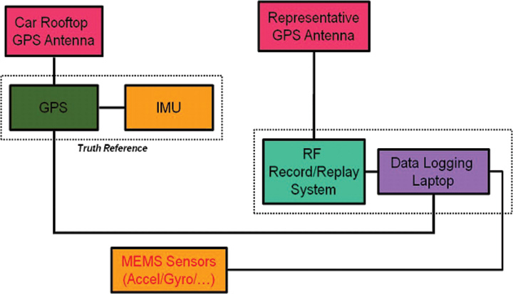
This article addresses how best to quantify “which navigation system performs best” in a realistic testing scenario. The methodology focuses on land vehicles navigating in urban environments, but applies equally well to pedestrian navigation and can be adapted for testing assisted-GNSS implementations. During a drive test, the truth-reference system and RF recording system log samples to disk, with no need for the receivers under test to be included during the actual drive.
By Eric Vinande, Brian Weinstein, Tianxing Chu, and Dennis Akos, University of Colorado, Boulder
FIGURE 1. Traditional in-vehicle receiver testing.
Radio frequency record-and-playback systems (RPS) have recently become commercially available. These systems sample the RF environment and store it to disk during a drive test and can replay it through receivers back in the lab environment. Here we explore the improvements in dynamic testing methodology created by these units.
RPS test system installation.
RPS constitute a stark contrast to more traditional signal simulators that use pre-defined trajectories and mathematical models to determine appropriate RF output. Signal simulators attempt to reproduce environmental error factors such as multipath, inertial aiding system errors, and building and vehicle obstructions. They rely on mathematical models to simulate these various error sources. In some cases they do a reasonable job of reproducing these errors, but the dynamic urban environment is so complex (for example, rapidly varying/fading signal strength(s), multiple multipath signals, short/long duration obstructions of multiple layers) that even a sophisticated mathematical model can not replicate all effects completely. Some simulators include software that enables the user to define a trajectory and a limited amount of urban scenario details. Again, only so much realism can be created in a simulation environment. Existing testing standards are simulator-based, and as such, are circumscribed by the signal simulator limitations in representing a dynamic environment.
Positioning performance of a satellite navigation receiver under test (RUT) is coupled with its RF front-end system and local oscillator quality. Because of the variation in RF components between RUTs, some likely have superior RF interference (RFI) immunity. RFI can be a serious issue in certain land vehicles due to on-board electrical systems or because of external interference sources.
This article describes a testing method applicable to all receiver types, and complementary to that described in the December 2009 GPS World article by Mitelman and colleagues, “Testing Software Receivers,” regarding validation testing within a production environment. Added elements include taking into account truth-system uncertainty and a repeatability verification of the RF playback process through non-deterministic hardware receivers.
We present here the dynamic testing approach currently used at the University of Colorado in Boulder for receiver evaluation and comparison in the urban environment. The approach also includes the ability to assess the effect of sensor augmentations (for example, inertial, environmental) on positioning performance.
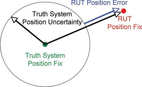
Truth Reference. Comparison with a truth reference system is essential for evaluation of satellite navigation receivers. For dynamic testing, this typically includes a survey-grade receiver coupled with a tactical-grade (or better) inertial measurement unit (IMU) and associated carrier-phase differential post-processing software. This software is filter-based and provides a positioning-error estimate in various components. Truth reference systems provide a continuous position estimate whose quality can vary depending on factors experienced in the urban environment, including length of full/partial satellite signal outage. In this study, we subtracted the 99th-percentile horizontal positioning error estimate of the truth system from the nominal RUT positioning error at each reporting epoch, as shown in Figure 2.
If the RUT position happens to lie within the truth-system position uncertainty, it is not considered to have any position error.
We focus here on a method to evaluate and compare mass-market, consumer-grade receivers to survey-grade receivers. One difference between these two receiver types is the way they handle the trade-off between accuracy and availability. Consumer receivers strive to provide the user with the highest availability, whereas survey receivers’ goal is to maximize accuracy. As a result, consumer-grade receivers will produce more regular position updates in harsh signal-tracking conditions, but must sacrifice accuracy to do so.
FIGURE 2. RUT position error calculation
Current Testing Standards
Currently accepted A-GPS standards such as those used by the 3rd Generation Partnership Project (3GPP) provide very limited dynamic testing in simulated urban conditions, being mainly designed to evaluate the first position calculation achieved in a particular simulated scenario. High-sensitivity receivers that pass or greatly exceed the 3GPP tests, in our opinion, are not guaranteed to have superior navigation performance in urban areas. Also, local oscillator performance is not specified. The trajectory dynamics imposed can actually be much smaller than the clock dynamics of a very low-cost local oscillator. A GPS receiver cannot tell the difference between the two and must track the effective Doppler variation.
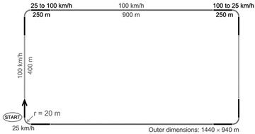
The 3GPP defines five independent tests for A-GPS receiver certification. They include tests in the areas of: sensitivity with coarse/fine time assistance, nominal accuracy, dynamic range, multipath performance, and moving scenario/periodic update performance. The last three tests include elements that ostensibly pertain to the urban environment. These tests specify discrete, constant signal power levels for implementation in a hardware signal simulator. The discrepancy between the 3GPP-prescribed signal levels and those observed during actual drive testing is detailed as follows.
The 3GPP moving scenario/periodic update performance test trajectory is shown in Figure 3.
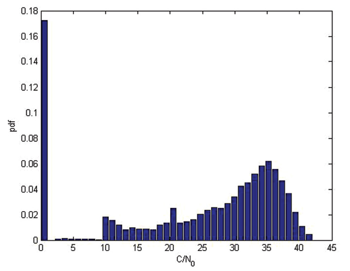
This test profile calls for the simulation of five satellites with a constant signal strength of 2130 dBm while the vehicle travels around the racetrack trajectory. In contrast, during an actual drive test in an urban area, a receiver reported the distribution of carrier-to-noise-density values for all tracked satellites as shown in Figure 4. This more accurately shows the range of signal strengths that should be expected in urban conditions.
FIGURE 4. Drive-test C/N0 distribution
The 3GPP moving test is considered passed if positions are reported regularly, and 95 percent of them are within 100 meters of the true position. This is not a particularly difficult test for a RUT to retain signal lock through, as the linear acceleration is about 0.15 g and the centripetal acceleration is about 0.25 g.
It is difficult for independent third parties to carry out a receiver evaluation following 3GPP guidelines as several of the tests require receiver restarts, which in turn requires testing automation. Depending on the receiver-evaluation hardware availability, restart commands may not be available to to an independent evaluator.
3GPP receiver testing results are quoted as pass or fail over a large number of short evaluations. For the dynamic environment, the system performance over continuous time is required to make a proper comparison between evaluated receivers.
In general, evaluating the GPS engines embedded within cell phones or other devices is difficult. Most are not made to interface with an external antenna, and the mere act of adding an antenna connection can significantly alter performance. The output format is not always documented, if it is even available to an end user. To allow fair across-the-board comparisons, GPS chipset manufacturers should make available development kits that have external antenna connections and well-documented message output formats.
Drive-Test Configuration
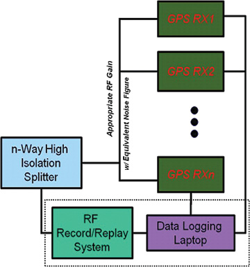
Current live dynamic testing requires multiple systems to be operating in a moving vehicle (see opening Figure 1). A truth-reference system, usually a high-grade GPS/INS device along with post-processing, provides the basis to which all other RUT are compared. This system requires a dedicated vehicle rooftop antenna with the best possible sky view, separate from a lower-grade test antenna located within the vehicle. Each RUT is connected to the representative consumer-grade antenna located in the vehicle through a high-isolation splitter that suppresses inter-receiver interference. It is important at this point that the gain be set appropriately for each RUT, depending on the front-end expectations while maintaining an equivalent noise figure across all receivers.
Visualization Methods
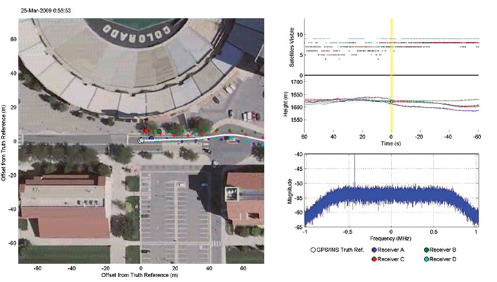
In addition to quantitative methods, we have created a qualitative visualization to assist with interpretation of the raw data. The same parsed data sets that provide the statistical script input are fed into a viewer script along with the post-processed truth reference data. With the truth-reference system data plotted in the center of the screen, each RUT is then plotted the correct distance and direction away, based on the distance and direction of error compared to truth. The receiver plots are overlaid onto Google Earth images centered on the truth-reference location. Plots of number of satellites utilized (top right of Figure 5) and elevation (middle right) as reported by each receiver and the sampled RF spectrum (lower right) are also included.
For each reporting epoch, based on the data frequency of the truth-reference system, a frame is generated with the aforementioned characteristics. These frames are gathered and encoded into a movie clip which can then be used as a quick and simple qualitative tool for receiver comparison. Figure 5 shows an individual movie frame. A forward-looking camera capability is also being added to this movie so the test environment can be documented from multiple angles.
FIGURE 5. Movie visualization screenshot
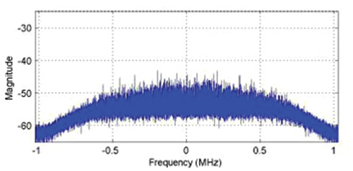
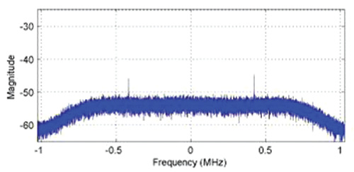
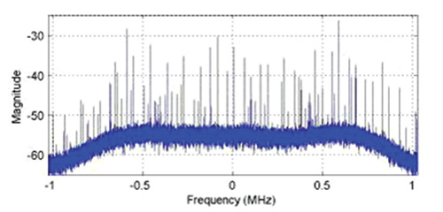
While observing this movie, variations in the sampled RF spectrum from interference or blockages can be associated with the current landscape. Locations of RFI sources can be identified and avoided (or included) in future testing. These RFI and significant blockage locations are of interest for receiver RF component and navigation filter development. The next three figures show spectrum snapshots during various parts of a drive test. In Figure 6, the cumulative GPS spectra rises above the noise floor and is visible during open sky conditions. While below ground level, Figure 7 shows only the front-end filter shape (and relatively minor RFI). Figure 8 shows an example of severe RFI when near a specific parking garage location.
FIGURE 6. Open-sky spectrum (centered on 1575.42 MHz)
FIGURE 7. Spectrum while below ground level (centered on 1575.42 MHz).
FIGURE 8. Spectrum near interference source (centered on 1575.42 MHz).
Record/Playback Concept
To overcome the limitations of hardware signal simulators and repeated vehicle drive testing, the RF record/playback testing method is utilized at the university. Commercially available equipment, capable of recording and playing back an RF signal, has recently become available. Equipment options exist for between $10,000–100,000, with 1–16 bit sampling and 4–25 MHz front-end bandwidth.
Figures 9 and 10 show the concept of “record once, playback many times.” During a drive test, the truth-reference system and RF recording system log samples to disk. There is no need for the RUT to be included during the actual drive test.
In the laboratory, the logged RF samples are replayed through a splitter to all RUT. The effect of receiver configuration changes can be evaluated without having to repeat the drive test. At a later time, additional receivers can also be tested using the same stored RF sample file.
During separate record and playback phases, testing considerations and methods discussed previously are implemented.
Since the recording process can only obviously capture current conditions, additional drive-test collections are required if different satellite geometry is desired, or if additional representative antennas need to be evaluated.
Repeatability of RPS Testing
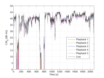
To validate that the playback signal levels were not significantly different from live signals, we conducted an urban, dynamic evaluation. Figure 11 shows that there is typically not more than a 1 dB difference in reported C/N0 between live and playback modes when testing a receiver that only reported integer values. The two dropout instances were excursions into parking garages.
FIGURE 11. Live and playback C/N0 values
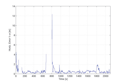
Figure 12 compares the navigation statistics between replays, using the same five playbacks as in Figure 11. The playbacks show a 1-sigma horizontal position solution spread under 1 meter for approximately 83 percent of the test.
FIGURE 12. Playback Horizontal Position Error Spread.
These two figures verify the repeatability of the RPS testing method and solidify it as an alternative to both signal-simulator testing and live testing of satellite navigation receivers.
Denver Testing Method
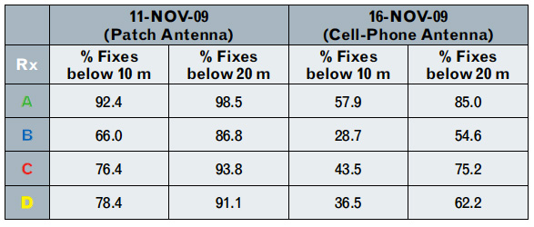
To evaluate the RPS concept, we conducted tests in three locations: Boulder, Denver, and Interstate Highway 70, all in Colorado. The Boulder and Denver locations were urban collections, while the Interstate 70 location was a natural canyon with significant elevation change. The collection at each location was repeated with two different representative antennas (patch and cell phone) at nearly the same sidereal time in order to keep the overhead satellite constellation similar.
We examine here the November 11 and 16 Denver tests. The November 11 test used a patch antenna that places nearly all its gain in the upward direction, making it more immune to interfering sources below and to its sides. Figure 13 shows the patch antenn
a location on the van, as well as the truth-system antenna location utilized for testing on both days.
FIGURE 13. Patch antenna (dashboard) and truth-system antenna (rooftop) locations.
The November 16 test used a cell-phone GPS antenna that does not have a preferential gain direction, making it more susceptible to interfering sources below and to its sides. This antenna type is representative of the typical low-cost antenna (in some cases as simple as a piece of wire) found in consumer cell phones. Figure 14 shows the cell-phone antenna suction-cup mounted to the front window of the testing van. The representative antenna mounting location was chosen to minimize locally-generated RFI effects while also being representative of a typical vehicle-use case.
FIGURE 14. Cell-phone antenna location.
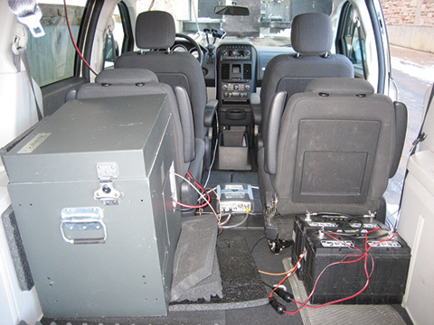
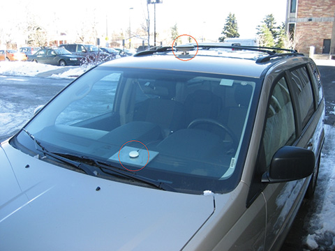
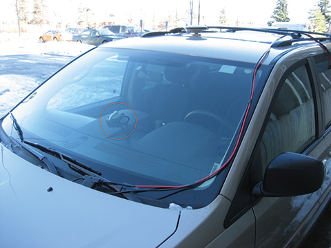
The required equipment and connections are minimal when performing RPS drive testing, as no RUTs are included. The inset to Figure 1 at the beginning of this article shows the RPS unit in the rear of the van, mounted on layers of foam to reduce vibration, which, if not properly addressed, can cause errors in mechanical hard drives writing data at high rates. Also visible are the truth receiver on the center of the van floor, and the car batteries for powering it and the IMU. The IMU is mounted to the vehicle frame and is not shown.
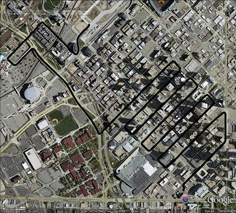
The test drive trajectory through Denver on November 11 and 16 as reported by the truth system is shown in black in Figure 15 and is also repeated in Figures 16 and 17. The test lasted approximately 40 minutes on both days. It started in the upper left part of Figure 15 and continued zig-zagging through downtown to the lower right.
FIGURE 15. Truth trajectory for November 11 and 16 tests.
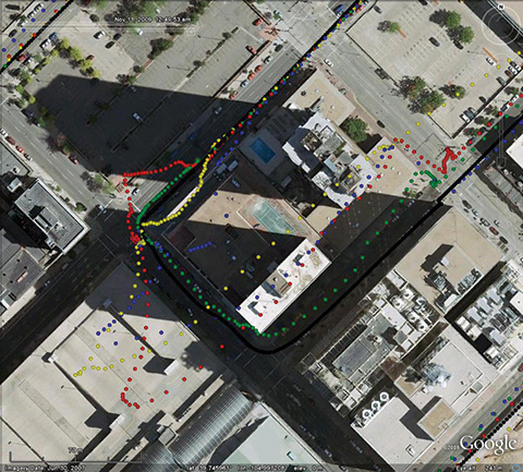
Figures 16 and 17 show particularly difficult blocks for the four receivers tested under the replay method. These receivers are denoted A (green), B (blue), C (red), and D (yellow).
FIGURE 16. Difficult block #1 during November 11 test and truth system antenna (rooftop) locations.
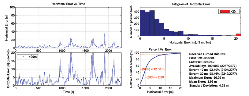
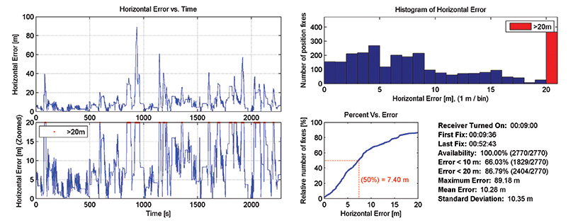
The horizontal positioning error statistics for two receivers on the November 11 test are shown in Figures 18 and 19. The left side shows horizontal error in two different zoom levels. The right side shows a histogram and cumulative distribution of errors, and several reporting metrics over the entire test. Even though receiver A in general outperformed receiver B, from the error time histories there are noticeable periods where both receivers simultaneously had positioning difficulties.
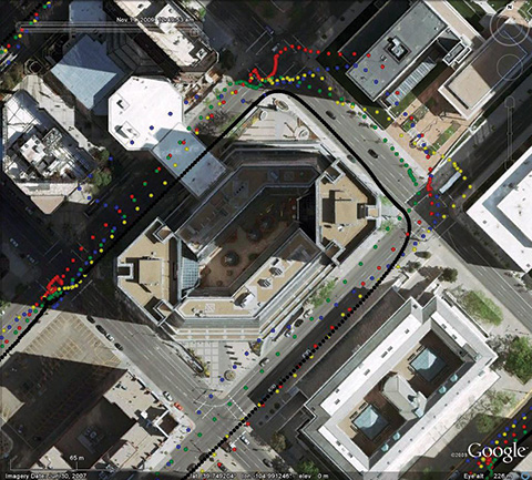
FIGURE 17. Difficult block #2 during November 11 test.
Table 1 summarizes the horizontal positioning statistics for all receivers during both tests. Positioning accuracy was severely degraded when replaying samples collected with the cell-phone antenna as compared to the patch antenna. Receiver A was the most accurate across both tests, while receiver B was the least accurate. The uncertainty of the truth system was subtracted out when producing the horizontal positioning results for all receivers.
Table 1
Conclusions
The record-and-playback system testing approach, in our opinion, represents the best way to test hardware receivers. It overcomes the fidelity limits of simulator-based testing, especially when considering the difficult-to-model urban environment. During receiver development, it requires only a single drive test for each location, as sampled RF data can be replayed from disk.
Having demonstrated that RPS testing is repeatable, we have produced a library of RF sample files representing real-world conditions for continued receiver development and testing purposes.
Eric Vinande is Ph.D. student at the University of Colorado studying GPS/MEMS inertial sensor integration and urban RFI aspects.
Brian Weinstein is a BSEE student participating in the Undergraduate Research Opportunity Program for GNSS receiver testing at the University of Colorado.
Tianxing Chu is a visiting researcher at the University of Colorado from Peking University where he is a Ph.D. student.
Dennis Akos is an associate professor within the Aerospace Engineering Sciences Department at the University of Colorado with concurrent appointments at Stanford University and Luleå University of Technology.
Manufacturers
Development of the methodology described here used two different RPS systems, one from LabSat (RaceLogic) and one from Averna. The test data come from the Averna system.