Tag: Beta OPUS Project

  • NGS replacing NGS 58 and 59 documents: Specifications for GNSS geodetic control surveys using OPUS projects

    NGS replacing NGS 58 and 59 documents: Specifications for GNSS geodetic control surveys using OPUS projects

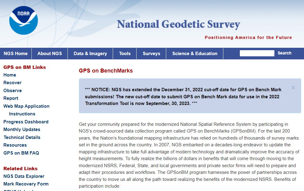
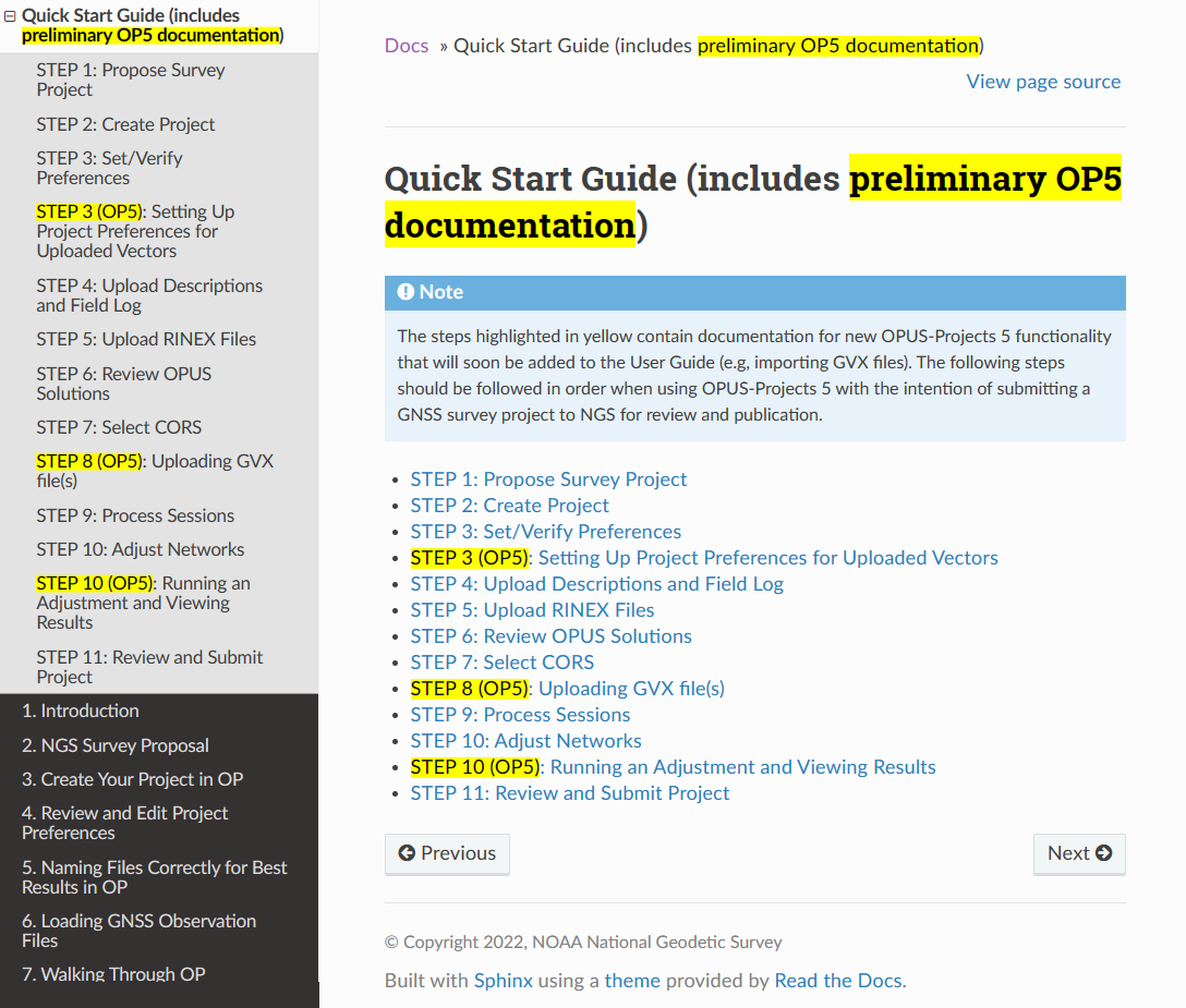
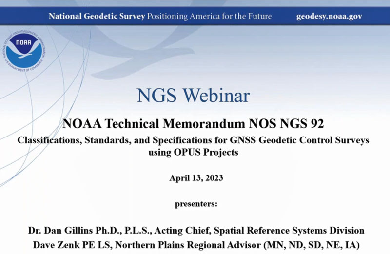
    On April 13, the National Geodetic Survey (NGS) held a webinar that described the classifications, accuracy standards and general specifications for GNSS geodetic control surveys using OPUS Projects. The webinar provided a summary of NOAA Technical Memorandum NOS NGS 92, which will be published after it has been through a final review. The presentation can be downloaded here and here. I will highlight some important sections of the webinar, but would also encourage readers to download it and watch it in its entirety.

    NGS April 2023 Webinar (Credit: NGS Website)
    NGS April 2023 Webinar (Credit: NGS Website)

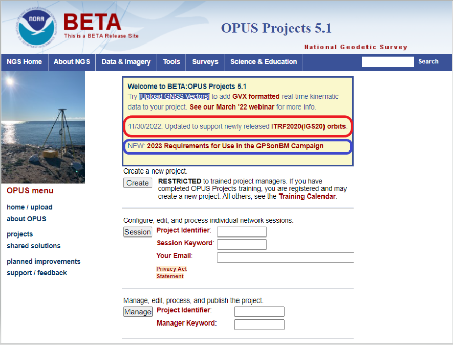
    As described in my March column, OPUS Project 5.1 routine now allows the use of RTN vectors and post-processed vectors from vender software. See my March column or NGS’ January 2023 webinar to learn more about OPUS Project 5.1.

    The April webinar described the specifications that are required for GNSS surveys that will be submitted to NGS for publication. It was noted that these specifications are limited to the use of OPUS Project (version 5) for the establishment of North American Datum of 1983 (1983) coordinates and orthometric heights of vertical datums that are part of the current National Spatial Reference System (NSRS). The intent of the NOAA Technical Memorandum NOS NGS 92 is to replace NOAA Technical Memorandum NOS NGS 58 — “Guidelines for Establishing GPS-Derived Ellipsoid Heights, (Standards: 2 cm and 5 cm), Version 4.3” of November 1997, and NOAA Technical Memorandum NOS NGS 59 — “Guidelines for Establishing GPS-Derived Orthometric Heights” of March 2008.

    Why replace the guidelines now?

    First, there have been improvements in GNSS processing and technology since NOS NGS 58 was published in 1997. The guidelines did not consider the use of real-time kinematic (RTK) technology, the number of NOAA CORS has significantly increased since the 1990s, and NGS’ web-based software OPUS Project 5.1 now allows the use of RTN vectors and post-processed vectors from vender software. In my opinion, there is a difference between guidelines and specifications. Guidelines provide recommended procedures to meet a specific outcome or standard while specifications are an explicit set of requirements that need to be satisfied to meet a specific outcome or standard. In other words, guidelines are general recommendations, and by nature, should be open to interpretation and revised to meet new technological developments.

    The webinar described the standards and specifications in 10 tables, which are displayed below. I will highlight a few of these tables that address how RTN vectors and post-processed vectors from vender software can be included in OPUS Project 5.1.

    List of Tables: 

    1. Classifications of Network and Local Accuracy
    2. Description of Mark Types and Anticipated Usage
    3. Observation Method Requirements for Mark Types
    4. Standards for Observation Requirements by Method
    5. Standards for Network Design
    6. Standards for Monumentation
    7. Standards for Session Processing and Adjustment Results
    8. Standards for Achieving Valid Orthometric Heights
    9. Standards for Equipment Used in Field Observations and Office Procedures
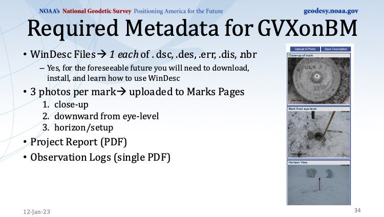
    10. Standards for Required Documentation

    First, NGS has defined three classifications for network and local accuracies in Table 1 — primary, secondary and local. As expected, the accuracy values are different based on the classification. See Table 1. Table 4 provides the observation specifications for each classification.

    Table 1. (Credit: NGS Website)
    Table 1. (Credit: NGS Website)

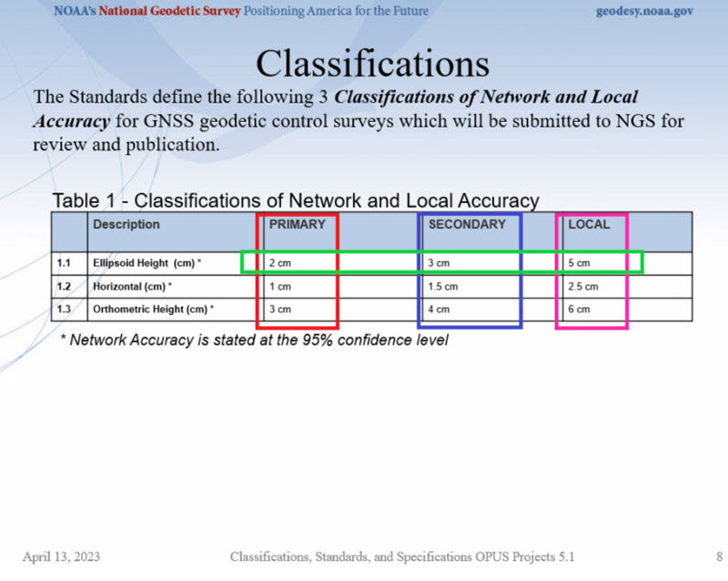
    Table 2 provides definitions that are important to understand. NGS designates three different types of marks in the network design — NCN CORS, GVX base, and passive. See Table 2. Each of these types of marks has its own observation requirements which is described in Table 4.

    Table 2. (Credit: NGS Website)
    Table 2. (Credit: NGS Website)

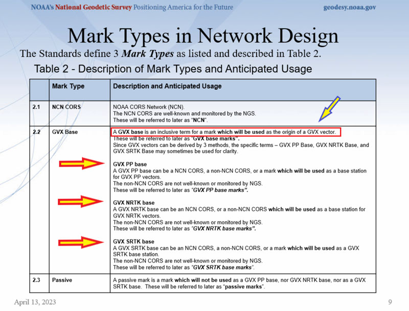
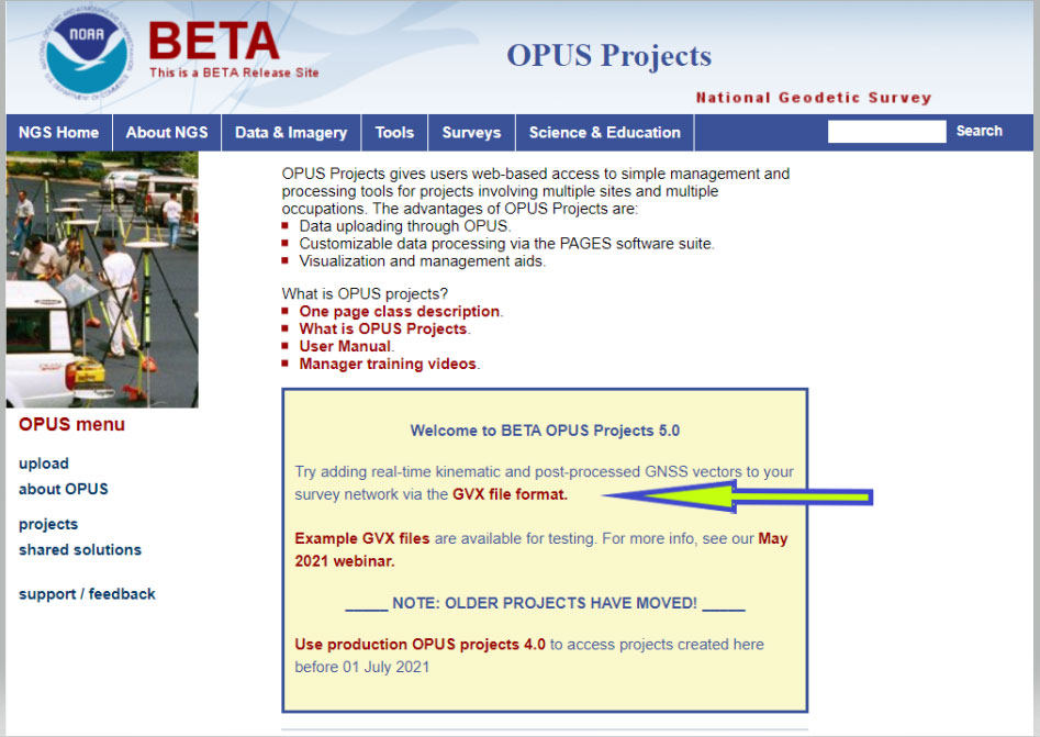
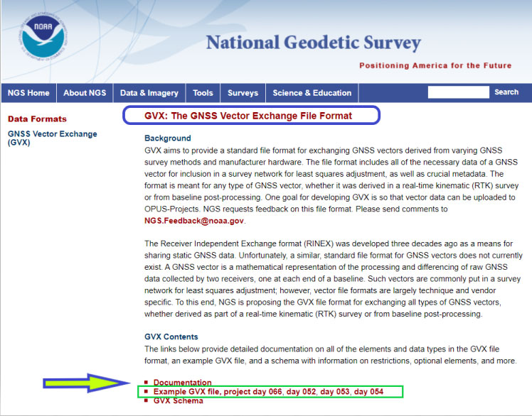
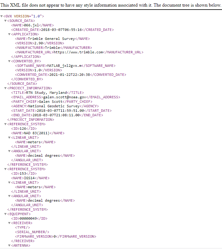
    Information about the GVX vector format can be obtained here. Basically, the GNSS Vector Exchange provides a standard file format for exchanging GNSS vectors derived from varying GNSS survey methods and manufacturer hardware. NGS’s goal for developing GVX is to make it possible to upload vector data to OPUS-Projects. There are different observation specifications for OPUS Project processing GNSS data and for OPUS Projects accepting GNSS data observed and processed by manufacturer hardware and software — that is GVX data.

    Please see my October 2021 column for more information on NGS’s GVX format.

    A note on abbreviations: PP stands for post-processed; that is, OPUS PP are baselines processed in OPUS Project. GVX PP are baselines processed using a vendor’s software. GVX NRTK and SRTK are baselines from a vendor’s RTK systems.

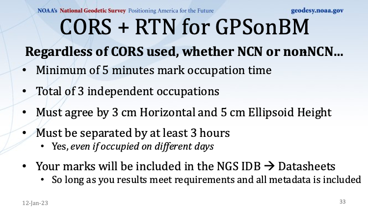
    Table 4 provides the observation requirements for primary, secondary, and local marks. I have highlighted the following items in that table:

    • All methods must repeat occupations and repeat sessions/occupations must be offset by 3 to 21 hours. 
    • Required total static GNSS observation time for OPUS PP is greater than total static GNSS observation time for GVX PP data. That said, OPUS PP requires at least two sessions while GVX PP requires at least three sessions. 
    • For GVX PP session, the duration of each session increases with distance and a GVX PP baseline cannot exceed 50 km (this is provided in Table 5: Standards for Network Design). 
    • For GVX NRTK, the number of sessions increases to six for primary marks, the duration of occupations decreases to 5 minutes, a GVX NRTK baseline cannot exceed 40 km (this is provided in Table 5 – Standards for Network Design), and the mark requires at least three occupations on different days. 
    • The use of GVX SRTK is not permitted for primary marks. 
    Table 4. (Credit: NGS Website)
    Table 4. (Credit: NGS Website)

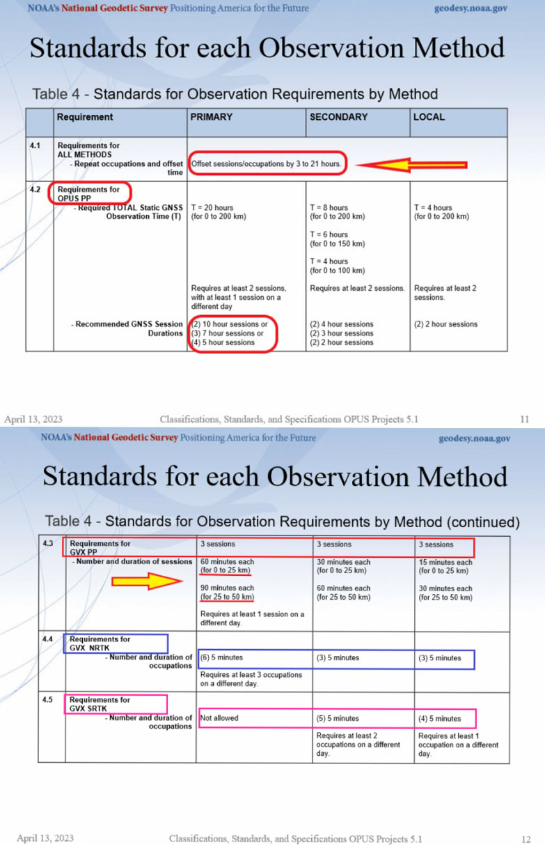
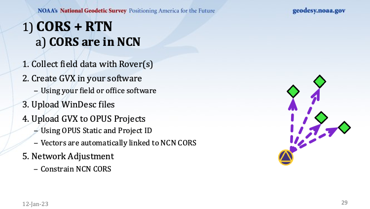
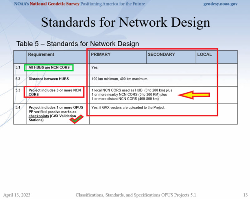
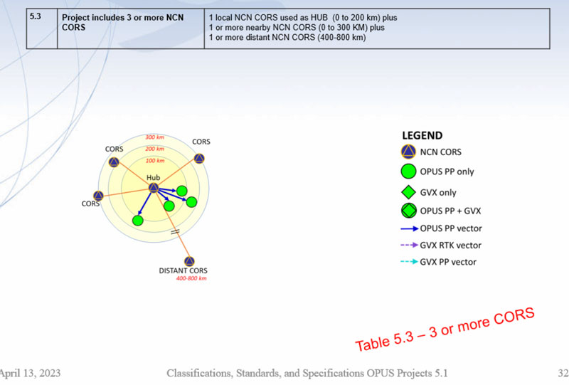
    Table 5 provides the specifications for network design; that is, the number of NOAA CORS required and the allowable distance from the HUB CORS. The image titled “Project includes 3 or more NCN CORS” provides a depiction of the specifications.

    Table 5. (Credit: NGS Website)
    Table 5. (Credit: NGS Website)

    Not all CORS are created equal, so users should evaluate the CORS they plan to include in their GNSS project. My December 2021 column discusses using NGS Map service to evaluate CORS data and plots. Some of the criteria that are used to evaluate CORS include the following: designated as “operational,” computed (measured) velocities rather than modeled (predicted) velocities, “consistent” data depicted in short-term time-series plots, network accuracies ~1 cm to 1.5 cm horizontally and less than ~2 cm to 3 cm in ellipsoid height.

    Project includes 3 or more NCN CORS. (Credit: NGS Website)
    Project includes 3 or more NCN CORS. (Credit: NGS Website)

    Specifications for GVX vectors are also provided in Table 5. As indicated in Table 5 and previously stated, GVX PP baselines are limited to 50 km and GVX NRTK vectors are limited to 40 km.   

    Table 5 continued. (Credit: NGS Website)
    Table 5 continued. (Credit: NGS Website)

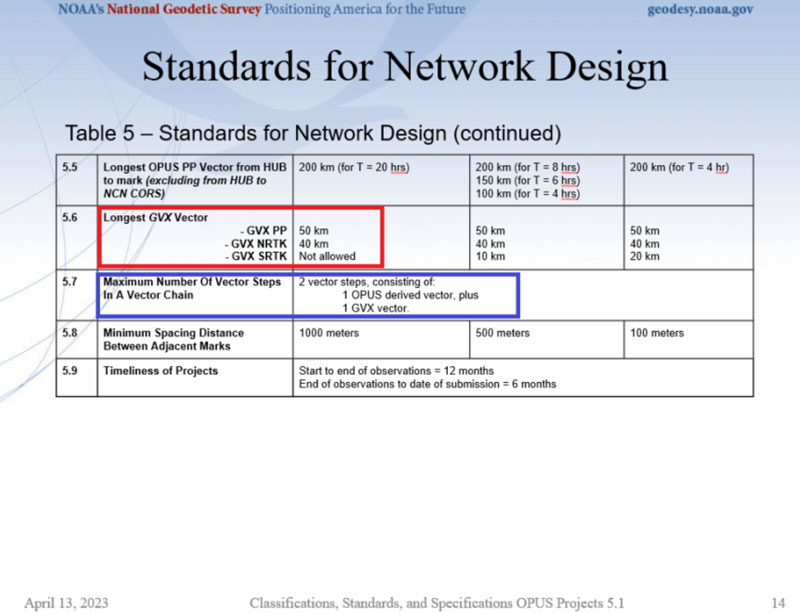
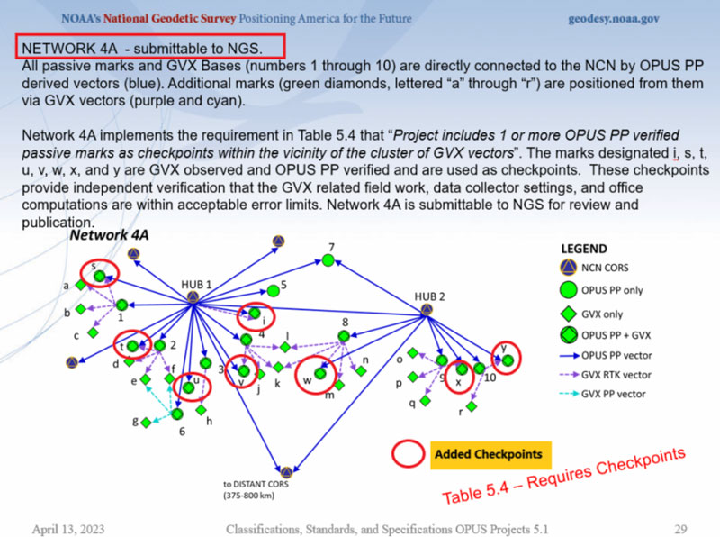
    An important specification that needs to be highlighted is that the maximum number of vector steps in a vector chain is two. This means there can only be one OPUS PP plus one GVX vector (either GVX PP or GVX RTK) in a vector chain. This is demonstrated in an example in the image below. Also, specification 5.4 states that if GVX vectors are uploaded to the project, then a project needs one or more OPUS PP verified passive marks as checkpoints (these are denoted as GVX Validation Stations). The checkpoint marks have been highlighted in the image below as well.  

    NETWORK 4A - Submittable to NGS. (Credit: NGS Website)
    NETWORK 4A – Submittable to NGS. (Credit: NGS Website)

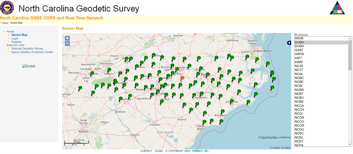
    If your state has many CORS with an NRTK, as North Carolina does, then the image below provides an example of how OPUS projects and GVX vectors can be used to efficiently and effectively establish primary control marks.

    NETWORK 8A – submittable to NGS. (Credit: NGS Website)
    NETWORK 8A – submittable to NGS (Credit: NGS Website)

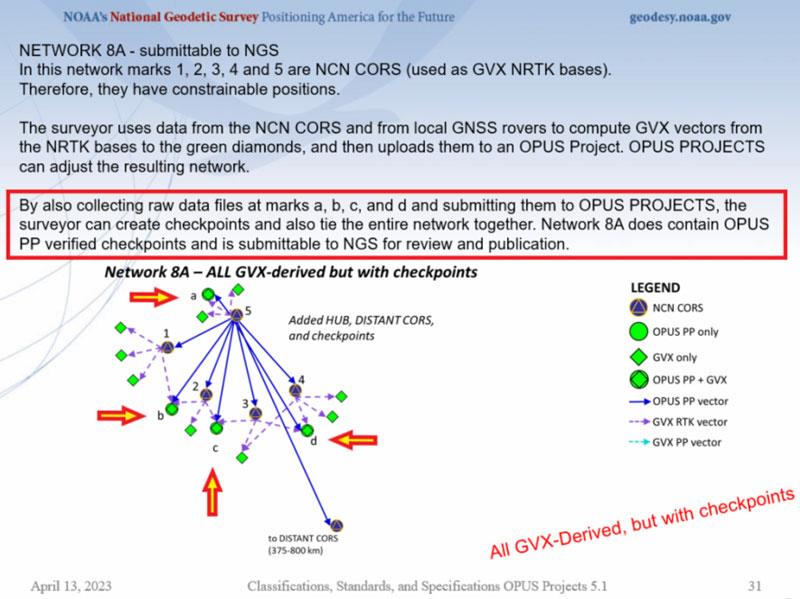
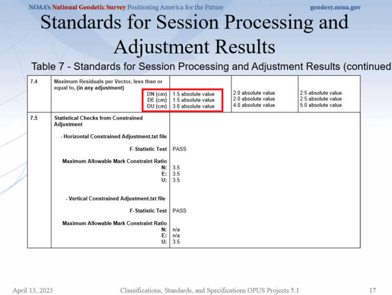
    Table 7 provides session processing and adjustment results. The achieved network standard highlighted in the image is the same as the classification standard provided in Table 1, which is what should be expected.   

    Table 7. (Credit: NGS Website)
    Table 7. (Credit: NGS Website)

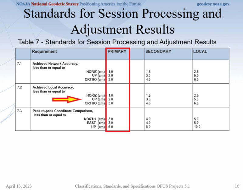
    The maximum residual values in dN, dE, and dU are also provided in Table 7. This requirement is important because it helps to ensure that outliers are detected and removed, especially in the height component.

    Table 7 continued. (Credit: NGS Website)
    Table 7 continued. (Credit: NGS Website)

    The webinar also had tables and diagrams for establishing orthometric heights. Table 8 and Figure 12 from the webinar provide a summary of the specifications. My January column described the specifications for establishing vertical control in the NSRS in more detail.

    Figure 12 from the webinar. (Credit: NGS Website)
    Figure 12 from the webinar. (Credit: NGS Website)

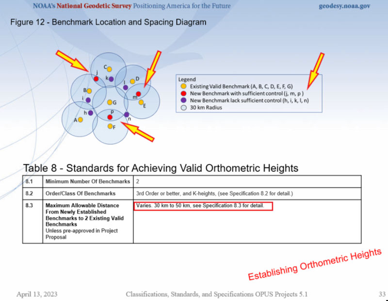
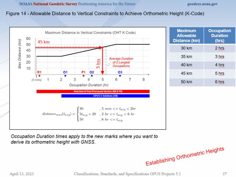
    The image below describes specification 8.3 in Table 8. It is important to recognize that the marks that will be used as vertical constraints need to be observed for two to six hours depending their distance from newly established marks.  

    Allowable distance to vertical constraints to achieve orthometric height. (Credit: NGS Website)
    Allowable distance to vertical constraints to achieve orthometric height. (Credit: NGS Website)

    A lot of information was presented at the webinar and I only highlighted some important sections of it in this column. I would encourage everyone to download the webinar and watch it in its entirety. It should also be noted that NOAA Technical Memorandum NOS NGS 92 is in draft status and is awaiting several final approvals before it is made available for public comment. That said, the webinar’s contents are subject to minor changes as NGS receives feedback. I would encourage everyone to contact the authors with questions and comments. 

  • New feature in OPUS Projects: Using RTN vectors to support 2022 Transformation tool

    New feature in OPUS Projects: Using RTN vectors to support 2022 Transformation tool

    February’s column focused on potential errors in orthometric heights using a digital barcode leveling system with multi-piece leveling rods. As stated in the column, businesses need to make decisions based on expenses and ultimately on the profit margin; but making a business decision that results in a bad technical outcome is never the right decision. This newsletter column is going to highlight a new feature in the National Geodetic Survey (NGS) Beta OPUS Projects 5.1 routine permitting the use of RTN vectors to support the development of the 2022 Transformation model.

    On Jan. 12, NGS held a webinar titled “Using RTN Data in OPUS Projects 5 for GPSonBM.” Users can download the video and PowerPoint slides here.

    I’ve been highlighting NGS’s GPS on Bench Mark program that supports the 2022 Transformation Tool in my columns since 2018. NGS delayed the completion date for the new modernized NSRS until 2025, so they have extended the cut-off date for submitting GPS on Bench Mark data for use in the 2022 Transformation Tool until Sept. 30.

    NGS GPS on BenchMarks Program (Image: NGS website)
    NGS GPS on BenchMarks Program (Image: NGS website)

    NGS has been developing tools that facilitate submitting data to the NGS GPS on BM campaign such as OPUS Share. The latest tool is the OPUS Project 5.1 routine that allows the use of RTN vectors. OPUS Projects 5.1 is a beta product, but NGS is now allowing users to use the routine to submit data for the GPS on BM campaign. My October 2021 column highlighted NGS’s Beta OPUS Projects 5.1.

    The 2023 requirements for using OPUS Projects in the GPS on BM program (Image: NGS website)
    The 2023 requirements for using OPUS Projects in the GPS on BM program (Image: NGS website)

    I’d like to note that OPUS has been updated to support the newly released ITRF2020 (IGS20) orbits. My October 2022column discussed the latest International Terrestrial Reference Frame of 2020 (ITRF2020) released by the International Earth Rotation and Reference System Service (IERS). A previous NGS news bulletin provided a statement about the new reference system and products.

    Excerpt from NGS News Bulletin (Image: NGS website)
    Excerpt from NGS News Bulletin (Image: NGS website)

    Clicking on the link titled “NEW: 2023 Requirements for Use in the GPSonBM Campaign” on the OPUS Projects 5.1 webpage provides the requirements for using OPUS Projects 5.1 and Real-Time Network (RTN) data to support the 2022 Transformation Tool; that is the 2023 GPS on BM campaign. There are five sections in the writeup: Introduction, Project Planning, Equipment and Configuration, Field Requirements and Office Requirements. The Introduction section states that the requirements are limited to the GPS on BM Campaign and will be replaced, or superseded, when NGS finishes its new GNSS surveying specifications.

    Introduction Section from Requirement Write Up (Image: NGS website)
    Introduction Section from Requirement Write Up (Image: NGS website)

    The project planning section of the announcement states that RTN vectors of 5-minute occupations can be used instead of the 4-hour occupations required for OPUS Share.

    Project Planning Section from Requirement Write Up (Image: NGS website)
    Project Planning Section from Requirement Write Up (Image: NGS website)

    However, the Field Requirement section states that the mark must be occupied three different times.

    “During the RTN survey, measure each mark in your project (including the RTN Validation Station) for a minimum of 5 minutes for three independent occupations. All three measurements must agree by 3 cm horizontal and 5 cm ellipsoid height. They also must be separated by at least 3 hours (even if occupied on different days). Plan to occupy a mark, go occupy a few more in the area, then circle back. Or rotate day-by-day,” the section states.

    Field requirements Section from Requirement Write Up (Image: NGS website)
    Field requirements Section from Requirement Write Up (Image: NGS website)

    As stated in the section on office requirements for using OPUS-Projects 5 in the 2023 GPS on BM Campaign writeup,“The OPUS-Projects User Guide provides instructions on how to run the software and submit a project to NGS. The User Guide states to follow the steps in the order listed below, and it explains steps 1 – 7 and 9 – 11 in detail. For step 8 and when including GVX data in OPUS-Projects 5, refer to those portions of the User Guide’s Quick Start which are highlighted in yellow. NGS is working on fully updating the User Guide to include more details; for now, use the Quick Start Guide for assistance with GVX.”

    OPUS Projects User Guide (Image: NGS website)
    OPUS Projects User Guide (Image: NGS website)
    Quick start guide. (Image: NGS website)
    Quick start guide. (Image: NGS website)

    I recently used OPUS Projects to analyze some GNSS results using Harris-Galveston Subsidence District CORS and PAMS GNSS data. I want to emphasize that it may seem like a lot of work the first time you use the routine, but NGS makes it fairly simple to complete each task. The manual is very complete and does a good job of describing every step. The manual can be downloaded here. In my experience, the most time-consuming task is creating the descriptions. There are several items that must be correctly entered because the answer to some entries affect the answers to other entries. That said, NGS supports a description entry software called WinDesc that facilitates entering the appropriate information. The OPUS Projects User Guide provides an appendix that describes using the WinDesc module to enter description metadata.

    For marks that are in the NGS database, known as the NGS Integrated Data Base (NGSIDB), WinDesc will import information from NGSIDB, thereby decreasing the number of entries users need to address. In other words, if the mark has a PID then it should be in the NGSIDB. If you are occupying a mark that is part of NGS GPS on Bench Marks website then it probably has a PID and a description in NGSIDB.

    Example of PID from Mark Priority List (Image: NGS website)
    Example of PID from Mark Priority List (Image: NGS website)

    I’ve included three slides from the Jan. 12 webinar that summarize the basic requirements.

    This slide is a depiction of how a CORS station must be connected to the RTN vectors. (Image: NGS website)
    This slide is a depiction of how a CORS station must be connected to the RTN vectors. (Image: NGS website)
    This slide provides the occupation and precision requirements. (Image: NGS website)
    This slide provides the occupation and precision requirements. (Image: NGS website)
    This slide provides a list of the required metadata for the project. (Image: NGS website)
    This slide provides a list of the required metadata for the project. (Image: NGS website)

    As for the requirement of at least three independent RTN occupations on different times, in my opinion at least one occupation should be on a different day. My October 2021 column addressed a study that reported on using RTN solutions to estimate accurate horizontal and vertical coordinates.

    The report stated, “When differenced with coordinates from a static GNSS survey campaign, the horizontal and vertical RMSE of the NRTK-derived coordinates was 2.3 cm horizontally and 4.5 cm vertically at 95% confidence. Repetitive NRTK vectors on each baseline differed between ± 2.4 cm horizontally and ± 3.4 cm vertically at 95% confidence.”

    The report also stated, “Adjustment of hybrid survey networks with four repeat NRTK vectors per bench mark produced network accuracies at 95% confidence for the adjusted coordinates at all bench marks less than 1 cm horizontally and 2 cm vertically (ellipsoid height).”

    The requirements are limited to the GPS on BM Campaign and will be replaced, or superseded, when NGS finishes its new GNSS surveying specifications.

    (Image: Screenshot of Accuracy of GNSS Observation from Tree Real-Time Networks in Maryland, USA)
    (Image: Screenshot of Accuracy of GNSS Observation from Tree Real-Time Networks in Maryland, USA)

    The paper by Gillins, et. al was presented at the 2019 FIG Working Week held in Hanoi, Vietnam, on April 22–26, 2019. The International Federation of Surveyors (FIG), involves a wide range of professional fields within the international surveying community; this includes surveying, cadastre, valuation, mapping, geodesy, hydrography, and geospatial and provides an international forum for discussion and development to promote professional practice and standards. FIG meetings are held all over the world. I’d like to highlight that the 2023 FIG Working Week is going to be held in Orlando, Florida, on May 28 – June 1, 2023.

    NGS will be presenting a full-day worth of content on NSRS Modernization during the FIG Working Week 2023. For the first time in more than 20 years, this annual FIG gathering will take place in the United States, hosted by the National Society of Professional Surveyors (NSPS).

    I’ve participated in several FIG meetings. I’ve learned a lot from presentations as well as holding hallway meetings with experts from the international surveying and mapping community. All geospatial users should plan on attending this event. I have provided information about the FIG commissions in my August 2021 newsletter. I would encourage everyone to visit the FIG website and review the information about the 2023 FIG Working Week. The a list of the FIG Commissions can be found here. More information can be obtained on each commission by clicking on its title.

    Future columns will highlight the FIG Working Week as the agenda is developed. I would encourage everyone to check NGS’s Website for updates on Beta products and new surveying specifications. Geospatial users should also subscribe to NGS’s News Services at the following here. Check out the NGS News Services site for what’s available.

  • NGS Beta OPUS released, accepting RTK and post-processed data

    NGS Beta OPUS released, accepting RTK and post-processed data

    On Sept. 16, the National Geodetic Survey (NGS) released the latest beta version of OPUS, called Beta OPUS Projects 5.0.  This version of OPUS now accepts real-time kinematic data and post-processed GNSS vectors from vendor software. See the box titled “Beta OPUS Projects 5.0 Webpage” on the website.

    As stated in the announcement, NGS has developed a file format for submitted real-time kinematic (RTK) data and post-processed GNSS vectors from vendor software to NGS. It is denoted as GNSS Vector Exchange Format (GVX).  This format enables NGS to incorporate the data into its GNSS processing routines.

    This is similar to the original Receiver Independent Exchange Format (RINEX) developed for making post-processing more efficient when combining GNSS data from manufacturers outputting raw GPS data in varying file formats. In my opinion, this is a significant improvement to NGS’s OPUS web utility.

    Beta OPUS Projects 5.0 Webpage

    Image: NGS website
    Image: NGS website

    Users can obtain background information about the GVX file format by clicking the link GVX file format. More detailed information about the GVX format can be obtained by clicking on the Documentation link.

    GNSS Vector Exchange File Format Webpage

    Image: NGS website
    Image: NGS website

    Basically, GVX is a standardized format for exchanging GNSS vectors derived from GNSS survey data using any manufacturer hardware and software results (see the box titled “Excerpt from Documentation of GVX”).  NGS designed the format so that it included all of the necessary data (including metadata) of a GNSS vector for incorporation into a survey network for performing a least-squares adjustment.

    Excerpt from Documentation of GVX

    (Link to PDF of GVX Documentation)

    To this end, this document proposes a new standardized file format known as the GNSS Vector Exchange Format (GVX). GVX aims to provide a standard format for exchanging GNSS vectors derived from varying GNSS survey methods and manufacturer hardware. The file format includes all of the necessary data of a GNSS vector for inclusion in a survey network for least squares adjustment, as well as metadata which describes the vector. The format is meant for any type of GNSS vector, whether it was derived in real-time or from baseline post-processing. GVX has been written in extensible markup language (XML). XML was chosen because it was designed to carry and store data in plain text format, it is easy to expand and/or upgrade to new operating systems, and it can be read by both humans and machines.

    A sample GVX file can be obtained by clicking on the link titled “Example of GVX file, project day 066, day 052, day 053, day 054.” As NGS states in the documentation, the output can be read both by humans and machines. What’s important is that it can be read by machines so the information can be incorporated into software programs. GNSS vendors have all the information they need to generate the output file to enable users to import the data into OPUS Project 5.0. Users will have to contact their software providers to determine whether their software routines generate the GVX output files.

    Example of GVX file, project day 066

    Image: NGS website
    Image: NGS website

    As I previously mentioned, this new option in OPUS Projects 5.0 is a significant improvement because many surveyors use RTK networks to obtain coordinates of marks. It will also facilitate the occupation of benchmarks with GNSS equipment to support the NGS 2022 Transformation tool. North Carolina, my home state, has a real-time network (RTN) that includes 96 GNSS CORS. (See the box titled “NC GNSS CORS and Real-Time Network.”) Currently, the North Carolina GNSS CORS and RTN has 4584 RTN service subscriptions.

    NC GNSS CORS and Real-Time Network

    Image: North Carolina Geodetic Survey Website
    Image: North Carolina Geodetic Survey Website

    I could not find a current list of public RTK networks in the United States, but I did locate a Jan. 7, 2014, GPS World article by Eric Gakstatter that provided a list of public RTK base stations in the country. It’s not up-to-date, but it highlights that, more than seven years ago, more than half of the U.S. states  had some kind of public RTK network. I would like to update the table, so I’d appreciate receiving information on the status of any public RTK network. Please feel free to send me an email at [email protected].

    List of Public RTK Base Stations in 2014

    Based on GPS World 2014 Article by Eric Gakstatter

    Note: States not listed did not have a public RTK network.

    State

    Status of Public Network

    Alabama Alabama Department of Transportation. Leica network.
    Alaska Two PBO RTK bases. One in Fairbanks and one in Palmer. Otherwise, no public service.
    Arizona Arizona State Cartographer’s Office. Leica network. Plate Boundary Observatory (single baseline).
    California California Real Time Network (CRTN) (single baseline).  Plate Boundary Observatory. Single baseline.
    Colorado Mesa County (Trimble network) and Plate Boundary Observatory (single baseline).
    Florida Florida Department of Transportation. Leica network.
    Idaho Plate Boundary Observatory (single baseline).
    Indiana Indiana Department of Transportation. Leica network.
    Iowa Iowa Department of Transportation. Leica network.
    Kentucky Kentucky Transportation Cabinet. Trimble network.
    Louisiana Louisiana State University. Trimble network.
    Maine Maine Department of Transportation. Trimble network.
    Massachusetts Massachusetts Department of Transportation. Leica network.
    Michigan Michigan Department of Transportation. Leica network.
    Minnesota Department of Transportation. Trimble network.
    Mississippi University of Southern Mississippi. Trimble network.
    Missouri Missouri Department of Transportation. Trimble network.
    Montana Plate Boundary Observatory (single baseline).
    Nevada Washoe County. Trimble network. Las Vegas Valley Water District. Leica network. Plate Boundary Observatory (single baseline).
    New Mexico Plate Boundary Observatory (single baseline).
    New York New York Department of Transportation. Leica network.
    North Carolina N.C. Department of Environment and Natural Resources. Trimble network. $500 one-time sign-up fee.
    Ohio Ohio Department of Transportation. Trimble network.
    Oregon Oregon Department of Transportation. Leica network. Plate Boundary Observatory (single baseline).
    South Carolina South Carolina Geodetic Survey. Public but charges a usage fee. Trimble network.
    Tennessee Tennessee Department of Transportation. Public but charges a usage fee. Topcon network.
    Texas Texas Department of Transportation. Public but only available to TxDOT employees and TxDOT contractors. Trimble network.
    Utah Utah Automated Geographic Reference Center.  Public but charges a usage fee. Trimble network. Plate Boundary Observatory (single baseline).
    Vermont Vermont Geodetic Survey. Trimble network.
    Washington Washington State Reference Network (Seattle Public Utilities). Trimble network. Public but charges a usage fee. Pierce County (Leica Network). Plate Boundary Observatory (single baseline).
    West Virginia West Virginia Department of Transportation. Trimble network.
    Wisconsin Wisconsin Department of Transportation. Trimble network.
    Wyoming Plate Boundary Observatory (single baseline).

    Why do I believe that this new option in OPUS Projects 5.0 is so important? Because it facilitates the incorporation of accurate GNSS-derived ellipsoid and orthometric heights into the National Spatial Reference System (NSRS).  With the development of improved algorithms, the results of coordinates computed using GNSS CORS/RTNs are more accurate today than ever before. During the last decade, there have been many studies analyzing GNSS data to estimate the accuracy values of coordinates from RTN data.

    A study titled “Accuracy of GNSS Observations from Three Real-Time Networks in Maryland, USA” by Daniel Gillins, Jacob Heck, Galen Scott, Kevin Jordan and Ryan Hippenstiel presented at FIG Working Week 2019 in Hanoi, Vietnam, April 22–26, 2019, provided a comparative evaluation on the accuracy of three independent RTNs constructed with differing hardware and software. Their study was based on 486, 5-minute duration GPS + GLONASS network RTK (NRTK) observations. The results indicated that repeat NRTK vectors could be combined to meet 1 cm horizontally and 2 cm vertically (ellipsoid height) accuracies at 95%. confidence.  See the box below.  It should be noted that the repeat observations should be observed at different times of the day (for instance, separated by > 2–3 hours), as well as, in my opinion, if possible at least more than two different days.

    Conclusions from Daniel Gillins, et al. 2019 FIG Paper

    A total of 486, 5-min duration, GPS+GLONASS NRTK observations were collected on nine bench marks distributed over a 4,000 square km area with rovers connected to three different RTNs in Maryland. Each RTN was developed with equipment and software from a different manufacturer, yet all three RTNs performed similarly in terms of accuracy. When differenced with coordinates from a static GNSS survey campaign, the horizontal and vertical RMSE of the NRTK-derived coordinates was 2.3 cm horizontally and 4.5 cm vertically at 95% confidence. Repetitive NRTK vectors on each baseline differed between ± 2.4 cm horizontally and ± 3.4 cm vertically at 95% confidence. As a final accuracy evaluation, hybrid survey networks consisting of repeat NRTK vectors and baseline solutions from post-processing static GPS data collected at RTN base stations and CORSs were adjusted by least squares. Prior to adjustment, the VCV matrices of the vectors were scaled by variance-component estimation. Adjustment of hybrid survey networks with four repeat NRTK vectors per bench mark produced network accuracies at 95% confidence for the adjusted coordinates at all bench marks less than 1 cm horizontally and 2 cm vertically (ellipsoid height). In addition to the benefits of using efficient and accurate NRTK vectors, the hybrid survey network approach makes use of redundant vectors for checking data and avoiding blunders. The approach also provides traceability because the NRTK vectors are tied to an RTN base station which is tied to CORS. Finally, these networks ensure the survey is referenced to the published coordinates of the CORSs which are held as constraints in the adjustment.

    Lastly, I would like to remind users that only three months remain until the December 31, 2021, cutoff to submit GPS on Benchmarks data that NGS can guarantee will be analyzed to compute the initial set of 2020.0 Reference Epoch Coordinates (RECs) that will be released with the Modernized NSRS. This initial set of RECs is currently the only set that NGS can guarantee will be used to build the 2022 Transformation Tool.  Once the transformation model is finalized, the NAVD 88 – NAPGD 2022 transformation values will be locked in and will not be updated as additional sets of RECs are computed.  If you have questions or concerns about this cut-off date, please contact your NGS Regional Geodetic Advisor, or drop NGS a line at [email protected].

    Beta OPUS Project 5.0 is a web-based tool that makes it easier to submit data to NGS.  I would encourage NSRS users to occupy as many benchmarks with GNSS equipment and submit the data to NGS before the Dec. 31 deadline.  Not only will these data help in improving the transformation model, but the marks will be included in the first computation of Reference Epoch Coordinates (RECs).  You can obtain information about Reference Epoch Coordinates in NGS’s NOAA Technical Report NOS NGS 67 publication titled “Blueprint for the Modernized NSRS, Part 3: Working in the Modernized NSRS.” A future column will address the different types of coordinates that will be distributed by NGS with the modernized NSRS.

  • NGS releases beta coordinates and multi-year CORS solution

    NGS releases beta coordinates and multi-year CORS solution

    My last column discussed the preliminary results of NGS’ second Multi-Year CORS Beta Solution of the National CORS. Since my last column, NGS announced the release of the beta version of the hybrid geoid model GEOID18 and, on Feb. 15, NGS officially released the Beta CORS ITRF2014 coordinates and velocities.

    This column provides the official links to NGS website that provide the beta coordinates and information about the latest multi-year CORS solution. Below is the NGS announcement of the beta release of the updated coordinates.

    Excerpt from Feb. 15, 2019, "NOTICE: New BETA Coordinates Available for CORS and OPUS". (Screenshot: NGS)
    Excerpt from Feb. 15, 2019, “NOTICE: New BETA Coordinates Available for CORS and OPUS”. (Screenshot: NGS)

    NGS also provides a notice of the new beta coordinates on the National Geodetic Survey homepage, with a link to the Beta CORS ITRF14 coordinates (see the highlighted section below).

    National Geodetic Survey homepage. (Screenshot: NGS)
    National Geodetic Survey homepage. (Screenshot: NGS)

    Clicking on the hyperlink labeled BETA CORS ITRF14 Coordinates directs you to the Multi-Years CORS Solution informational homepage.

    Information on Multi-Year CORS Solution 2. (Screenshot: NGS)
    Information on Multi-Year CORS Solution 2. (Screenshot: NGS)

    By clicking on the CORS Home button, the user is directed to the Beta CORS page.

    Beta CORS release page. (Screenshot: NGS)
    Beta CORS release page. (Screenshot: NGS)

    This page clearly states that the ITRF2014 reference frame for CORS is available as a beta product. It also implies that these coordinates are being used in other beta products such as OPUS. I’ll address this later in this column.

    Users can obtain information about the MYCS and other related products and services such as Beta OPUS by clicking on links provided on the Beta CORS homepage.

    Accessing information about ITRF2014 frame in NGS beta products. (Screenshot: NGA)
    Accessing information about ITRF2014 frame in NGS beta products. (Screenshot: NGA)

    It should be noted that these values are considered “beta” and are available to users for testing and feedback. NGS provides a statement about its beta release products. Basically, it states that users should only use beta products to test their workflows and never for official or production work.

    The NGS beta release statement. (Screenshot: NGS)
    The NGS beta release statement. (Screenshot: NGS)

    To facilitate testing of the beta CORS coordinates and velocities, NGS provides links to other beta products that will use the MYCS 2 coordinates and velocities.

    By clicking on the link labeled BETA OPUS on the beta CORS homepage, the user is directed to the BETA OPUS webpage. This page clearly states that the beta OPUS routine uses the new ITRF2014 reference frame for CORS.

    The NGS beta OPUS webpage. (Screenshot: NGS)
    The NGS beta OPUS webpage. (Screenshot: NGS)

    NGS also provides a link to Beta OPUS Projects that use the MCYS2 coordinates and velocities.

    Beta OPUS Projects webpage. (Screenshot: NGS)
    Beta OPUS Projects webpage. (Screenshot: NGS)

    Once again, the Beta OPUS Projects website clearly states that the beta version is using the CORS coordinates and velocities from the MYCS2. It also states that, at this time, NGS will not accept ITRF2014 submissions for publication. As previously stated, NGS’ beta products are for users to test their workflows and should never be used for official or production work.

    The Beta CORS webpage provides a lot of valuable information on the processing and establishment of the multi-years CORS solution. I’ve highlighted several of the sections below.

    First, by clicking on the link MYCS2 Processing, the user is directed to the section that describes the data used and the processing strategy.

    Excerpt from Beta CORS Webpage – MYCS2 Processing. (Screenshot: NGS)
    Excerpt from Beta CORS Webpage – MYCS2 Processing. (Screenshot: NGS)

    The following are highlights from the section:

    • The processing included data spanning 1996 to 2016 and involved around 3050 CORS, IGS and other (e.g., NGA) stations.
    • The corresponding input and output data occupied about 25 TB on the NGS computers.
    • The residual time series in the early 1990s showed exceptionally noisy behavior at times, which were deleted in the alignment/velocity computation stage.
    • The processing was performed in 3 steps:

    1. The global processing step solves for orbits, Earth Orientation Parameters (EOPs), hourly tropospheric delay parameters and weekly global (IGS) station positions in an IGS-NNR frame.

    2. The CORS processing step ties the remaining CORS to global, backbone, sites holding fixed estimated orbits, troposphere, EOPs and IGS station coordinates. This leads to estimated CORS coordinates in a no net rotation (NNR) frame.

    3. The last step is the alignment of the estimated coordinates with ITRF2014 and velocity estimation. This process was done in 15 iterations to achieve rigorous quality control and discontinuity detection.

    Linear velocities for all stations are estimated in the NGS realization of ITRF2014. NGS explains how this was implemented in the section titled “The velocity field relative to ITRF2014” (see box titled “Section Describing the Velocity Field Relative to ITRF2014”). The website provides figures that depict the horizontal and vertical velocities used in the processing.

    The following are a few highlights from the section:

    • Unless an earthquake or a post seismic adjustment occurred, the velocities of a station in between discontinuities are constrained to have the same value.
    • Stations that experience earthquakes, post seismic adjustment and in a few cases, non-uniform vertical motion, are allowed to have different velocities in between events as dictated by the data.
    • The webpage provides figures that depict the estimated horizontal and vertical CORS velocities.
    Section describing the velocity field relative to ITRF2014. (Screenshot: NGS)
    Section describing the velocity field relative to ITRF2014. (Screenshot: NGS)

    What users usually want to know is how much the coordinates have changed and what it means to their surveying activities. The section titled “Main Changes Compared to Previous Reference Frames” provides information and plots that depict the changes of coordinates.

    Section on changes in coordinates. (Screenshot: NGS)
    Section on changes in coordinates. (Screenshot: NGS)

    This section provides NAD83 (MYCS2) coordinate values minus NAD83 (MYCS1) coordinate values.

    The following are a few highlights from the section:

    • The ITRF2014 coordinates of all computed CORS coordinates from MYCS2 processing are converted to NAD83 (2011) using HTDP.
    • The resulting NAD83 (2011) coordinates are then compared to those obtained from MYCS1 at all common sites.
    • The coordinate differences are compared at epoch 2010.0 (MYCS2 – MYCS1).
    • The differences are less than 5 mm in most areas with some exceptions.
    • The largest differences are seen in southern Alaska.
    • Other visible changes are seen in areas of significant and real subsidence and in places where the time series are too short, such as in Iowa where almost all time series are three years long.
    • Vertical coordinates (ellipsoidal heights) are compared using the same criteria.
    • The stations with the HTDP estimated velocities from MYCS1 (no vertical velocities) show the largest differences. In addition, non-secular subsidence areas also show larger differences.

    By clicking on the plots, the user is directed to a larger figure that is easier to interpret. (See boxes titled “NAD83 (MYCS2) – NAD83 (MYCS1) Horizontal Position Differences” and “NAD83 (MYCS2) – NAD83 (MYCS1) Vertical Position Differences.”)

    NAD83 (MYCS2) - NAD83 (MYCS1) Horizontal Position Differences. (Screenshot: NGS)
    NAD83 (MYCS2) – NAD83 (MYCS1) Horizontal Position Differences. (Screenshot: NGS)
    NAD83 (MYCS2) - NAD83 (MYCS1) Vertical Position Differences. (Screenshot: NGS)
    NAD83 (MYCS2) – NAD83 (MYCS1) Vertical Position Differences. (Screenshot: NGS)

    NGS has done a tremendous job of explaining the MYCS2 process and results. As the results indicate, most differences between the MYCS1 and MYCS2 are small. Saying that, I would encourage all users to look at the NGS Beta webpages and obtain an understanding of the MYCS2 process and results. Users should also use the beta products and compare their results to the current production products to evaluate the CORS beta coordinates and velocities in their region of interest.

    Notice announcing beta version of Geoid18 on NGS homepage. (Screenshot: NGS)
    Notice announcing beta version of Geoid18 on NGS homepage. (Screenshot: NGS)

    It should also be noted that in late February, NGS released a beta version of the latest hybrid geoid model, Geoid18. This model can be accessed here; the site provides an opportunity for users to compute a beta Geoid18 value for a particular station.

    Excerpt from beta Geoid18 website. (Screenshot: NGS)
    Excerpt from beta Geoid18 website. (Screenshot: NGS)

    I would encourage all users to obtain an understanding of the new hybrid model. Once again, it should be noted that this model is a beta model for users to test their workflows and should never be used for official or production work.

    My next column will discuss the beta hybrid Geoid18 model, and the differences between the beta model and the official hybrid geoid model, Geoid12B.