GLONASS satellites traditionally use L1 and L2 frequency division multiple access (FDMA) signals. FDMA is characterized by a different transmit frequency for each satellite. Newer satellite generations also transmit an L3 code division multiple access (CDMA) signal. CDMA uses the same frequency but different ranging codes for individual satellites. The first GLONASS K2 satellite, with the space vehicle number R803, was launched in August 2023. It extends the range of CDMA signals to the L1 and L2 bands.
Figure 1. GLONASS K2 spectrum of the L1 frequency band. The different components of the L1 CDMA signal are indicated by colored boxes. L1SC: secured signal. L1OC: open service signal. (All figures provided by the authors)
Frequency spectra of R803, including these new signals, are shown in Figures 1 and 2. They were measured with the 30 m high-gain antenna of the German Space Operations Center (GSOC) in Weilheim, Germany, on Jan. 17, 2024. The largest and sharpest peak in the L1 band at 1,598.625 MHz originates from the 0.5 MHz binary phase-shift keying (BPSK) FDMA signal. The center peak of the L1 CDMA signal is located at 1,600.995 MHz. It is related to the L1 open service signal consisting of a data component (L1OCd) and a pilot component (L1OCp). L1OCd and L1OCp are combined by time-division multiplexing. The peaks that are ±5 MHz away from the L1 CDMA center frequency are introduced by the binary offset carrier (BOC) modulation of the secured L1SC signal. Prominent L1SC side lobes are visible ±15, ±25 and ±35 MHz offset from the center frequency. A quadrature phase-shift keying (QPSK) modulation is used to combine the L1OC and L1SC signals. The local minimum between 1,610 MHz and 1,614 MHz is caused by a notch filter onboard the satellite to protect radio astronomical observations of the Hydroxyl spectral line at 1,612 MHz.
Figure 2. GLONASS K2 spectrum of the L2 and L3 frequency bands. The different components of the L2 CDMA signal are indicated by colored boxes. L2SC: secured signal. L2xC stands for the time multiplexed L2OCp and L2 CSI signal. (All figures provided by the authors)
The L2 CDMA signal is composed of a signal for service information (L2 CSI) and the pilot open service navigation signal (L2OCp). As for L1, these two signals are time-division multiplexed and combined with the secured L2SC signal by QPSK. The left main lobe of the L2SC signals coincides with the L2 FDMA center frequency of 1,243.375 MHz. Both, the L2 CSI, as well as the L2OCp signal, contribute to the peak at the L2 CDMA center frequency at 1,248.06 MHz. The L3 CDMA signal is composed of 10 MHz BPSK data (L3OCd) and pilot (L3OCp) components resulting in a broad peak at 1,202.025 MHz.
FDMA and CDMA signals of GLONASS R803 were tracked with a JAVAD TRE_3S receiver with a prototype firmware located at GSOC in Oberpfaffenhofen, Germany. Figure 3 shows the differences between pseudo range and carrier phase observations for the FDMA and CDMA signals in the L1 and L2 frequency bands. Long-term ionospheric effects were removed by a second-order polynomial. Thus, remaining effects include short-term ionospheric variations, multipath, and observation noise. The standard deviation of the code–carrier combination is, in general, at the half-meter level. Due to their advanced design, the CDMA signals show an improved performance by 18% for L1 and even 31% for L2 compared to the legacy FDMA signals.
Figure 3. Code – carrier for GLONASS R803 FDMA and CDMA signals: L1 (left) and L2 (right). A second order polynomial has been removed and the CDMA signals are shifted by 4 m. (All figures provided by the authors)
Further launches of L1 and L2 CDMA-capable GLONASS K2 satellites are planned for the upcoming years. A constellation of at least 12 satellites is expected for 2030. To guarantee backwards compatibility, these satellites will also transmit the L1 and L2 FDMA signals. Further improvements in positioning accuracy are expected due to improved satellite clocks and inter-satellite laser ranging.
Russian Space Systems (2016), GLONASS Interface Control Document: Code Division Multiple Access Open Service Navigation Signal in L1 frequency band. Russian Rocket and Space Engineering and Information Systems Corporation, Joint Stock Company.
Russian Space Systems (2016), GLONASS Interface Control Document: Code Division Multiple Access Open Service Navigation Signal in L2 frequency band. Russian Rocket and Space Engineering and Information Systems Corporation, Joint Stock Company.
Manufacturers
GNSS data used in this article were collected with a JAVAD TRE_3S receiver. The spectral overviews were captured with a Rohde & Schwarz FSQ26 signal analyzer.
On Nov. 29, 2022, Russia launched the 51st Glonass-M satellite, completing a 20-year history that began on Dec. 10, 2003, with the launch of the first one. These satellites have been providing navigation signals in two frequency bands, L1OF and L2OF, to civil users since 2011.The average orbit lifetime for this type of satellite is more than 10 years, and 13 Glonass-M satellites operate beyond their guaranteed lifetime. The last set of seven satellites has been broadcasting the first CDMA civil signal, L3OC, by means of an additional antenna and onboard transmitter.
Starting this year, the constellation will be renewed by Glonass-K and Glonass-K2 satellites, which provide CDMA signals to users. Furthermore, four Glonass-K satellites will be supplemented with additional Glonass-K satellites and the first Glonass-K2 satellite. The K2 satellite has passed all ground tests and is ready to be transported to the launch site (Figure 1). Table 1 lists the technical characteristics of GLONASS satellites.
Figure 1. Artist’s rendition of the Glonass-K2 satellite in orbit.Table 1. The evolutions of GLONASS satellites.
The distinguishing feature of this satellite’s design is its two antenna arrays — one for CDMA signals with phase centers on the geometrical axis of the satellite, and the second for FDMA signals with phase centers shifted by 0.9 m relative to that axis.
The optical reflector panel center is also located on the satellite’s geometrical axis and passed through its mass center. It seems to be a very interesting scientific task to estimate the satellite flight model parameters by International Laser Ranging Service stations with the objective to improve the accuracy of the navigation signals for both antenna arrays.
Future GLONASS satellites will have a single antenna array for CDMA and FDMA signals (see Figure 2).
Figure 2. The evaluations of GLONASS satellites.
For analogous updates on the other three GNSS constellations, please see:
By Sergey Karutin, GLONASS designer general; Nicolay Testoedov, Director General, SC Information Satellite Systems; and Andrey Tulin, Director General, SC Russian Space Systems
This year has marked the 35th anniversary of the first GLONASS launch. During these years, the world has made great strides through high tech, and now no modern society can progress without satellite-based navigation.
Today’s urban resident can hardly do without a smartphone planning his route through traffic, determining the paid parking site location or getting a reminder of parking session completion once he has left the parking lot.
The search for the nearest pharmacy, gas station, restaurant or any other point of interest is of vital necessity today. The growing dependence of modern society on navigation signals-in-space increases the responsibilities of GNSS providers. At the same time, users long for simplicity in getting quality services. That is why this year the GLONASS team is going to set up its most ambitious program: improving the quality of the GLONASS services at a user level.
The traditional GLONASS conception of signal-in-space accuracy is now being augmented by the user level performance estimation. Due to the fact that the signal propagation environment contributes a lot to the positioning error budget, it is obvious that users need information that would reduce the influence of signal propagation path on the positioning accuracy.
Glonass-M satellites currently form the core of the GLONASS constellation, and with six ground spares now in stock, they will continue to do so for at least the next eight years. Therefore, in 2018 the new edition of L1 and L2 FDMA Interface Control Documents are to be published which will include the ionospheric and tropospheric models recommended in the recently released GLONASS CDMA Signals ICDs.
Glonass-K2 satellite (artist’s rendering).
We plan to use the spare bits within the navigation superframe of FDMA signals to transmit ionospheric parameters described in the General Description of the GLObal NAvigation Satellite System with the Code Division Multiple Access Signals ICD.
Studies being performed demonstrate up to 70 percent reduction in impact of ionospheric refraction when using the adaptive model transmitted by the three parameters: the numerical factor for the peak TEC (Total Electron Content) of F2 ionosphere layer, the solar activity index and the daily geomagnetic activity index. In the new CDMA signal message, these parameters are initially provided.
To enable the unanimity of technologies for reducing the hydrostatic component of the tropospheric delay, which accounts for 80 percent of its value, the both FDMA and CDMA Signals ICDs will include the latitudinal tropospheric model based on the preliminary set tabular values.
The preliminary design review for the technical baseline of the fourth-generation Glonass-K2 satellite has been passed this year. The new cubic arrangement of the platform enables mitigation of unmodeled forces and transition of propellant tank to the satellite’s center of mass.
This provides for the relative position constancy for the satellite’s center of mass and the satellite’s antenna phase center during the satellite’s lifetime. This platform arrangement also accommodates the whole ensemble of navigation signals (both CDMA and FDMA) on the single phased-array antenna system.
Glonass-K2 is equipped with the new atomic frequency standard composed of the legacy quantum frequency standard based on the cesium beam tube and the passive hydrogen maser. The miniature PHM with the relative daily stability of 5×10-15 will be installed onboard the satellite to be launched in 2020.
Introduction of the new satellite will enable a new constellation sustainment strategy — through the both dual launches by Angara-A5 launcher from Vostochny and single launches by Soyuz from Plesetsk — to provide on-demand replenishment of the constellation.
By 2020, when we celebrate the 25th anniversary of GLONASS full operational capability, all the efforts mentioned above will offer new quality of services to GLONASS users prioritized as per their needs.
Leica Geosystems, manufacturer of the Leica Viva GNSS Unlimited series and GS14 GNSS receiver, has added a new hybrid communication technology to its compact and powerful GNSS smart antenna. The latest generation Leica Viva GS14 GNSS now supports Verizon CDMA solutions along with all standard 2G/3G networks and UHF TX/RX radio in a single device, making it a professional GNSS receiver with all three communication systems built in. Users simply slide in their SIM card to experience instant connectivity for faster and easier field communications and SmartNet RTK corrections, the company said.
The Leica Viva GS14 3.75G&UHF supports 2G GPRS, 3G HSPa+, CDMA (EV DO) and UHF TX/RX radio between 450 and 470 MHz in one compact housing. Professionals can choose whether they want to use the UHF radio to transmit or receive work, a 2G/3G cellular network, or Verizon CDMA. No external equipment is required.
“The Leica Viva GS14 with its hybrid communication technology is the most advanced compact GNSS receiver in the market,” said Bernhard Richter, Leica Geosystems GNSS business director. “The addition of CDMA modem capability in a unique all-in-one design offers unmatched flexibility in communication choices.”
The Leica Viva GS14 3.75G&UHF is available today throughout the United States. Ordering information and details are available from all authorized U.S. Leica Geosystems representatives and dealers.
Rocky Mountain Tracking has added new GPS tracking devices that utilize CDMA cellular data networks in addition to its existing GSM-based devices.
CDMA coverage has steadily grown within North America during the last decade and is sometimes available in places where GSM networks don’t currently provide coverage. “Adding support for CDMA based devices allows us to offer our customers a choice of cellular provider based on their operational needs,” said Brad Borst, the company’s president.
“We’ve worked with our existing manufacturing and cellular service partners with the goal of being able to let our customers mix and match GSM and CDMA based devices into their fleet tracking strategy. The new CDMA devices look the same and function almost identically to their GSM counterparts,” says Borst. “CDMA devices will appeal to our customers operating in more remote locations within the United States while GSM continues to be a good option in metro areas and abroad.”
Rocky Mountain Tracking is a national GPS tracking device supplier and service provider.
Telit Wireless Solutions, provider of high-quality machine-to-machine (M2M) modules, services and solutions, has announced approval by Sprint for its CE910-DUAL cellular M2M module. A dual-band CDMA 1xRTT module, the CE910-DUAL allows Sprint M2M Solutions customers to deploy a wide range of M2M applications benefiting from reliable connectivity over Sprint’s nationwide network while enabling cost-sensitive business plans.
The CE910-DUAL packs high value features in its ultra-compact 28.2 x 28.2 x 2.04 mm Land Grid Array (LGA) package. USB 2.0 full-speed support and a rich set of drivers make it ideal for embedded applications requiring easy integration to platforms based on the latest desktop and mobile operating systems such as Windows and Linux. Full-duplex data rate of 153.6 Kpbs and extended operating temperature range of -30°C to +85°C make it a suitable platform for mobile and fixed applications such as vending, point-of-sale (POS), tracking, smart metering, and telematics devices.
“Sprint plans to maintain our CDMA 1xRTT network capability for the long term as part of our overall Network Vision strategy,” said Wayne Ward, vice president, M2M Group, Sprint. “We have been working with Telit for several years as a Sprint preferred provider and one of the leading module suppliers to the M2M industry and believe their xE910 form factor makes it easy for customers to deploy on either the EV-DO or 1xRTT CDMA Sprint networks.”
“With this approval, the cost-effectiveness, reliability and functionality of the CE910-DUAL module are accessible to Sprint M2M and Telit customers along with outstanding support and network connectivity from one of the nation’s top-rated cellular networks,” said Mike Ueland, senior vice president and general manager of Telit Wireless Solutions North America.
Part of the xE910 form factor family, the CE910-DUAL protects investments by offering complete compatibility with the DE910-DUAL, a Sprint-approved companion product for EV-DO Rev. A applications.
Sprint and u-blox have expanded their collaboration in support of Sprint’s commitment to the 2G (1xRTT) CDMA network. As a carrier committed to network choice, Sprint believes M2M customers should be able to choose or combine 2G, 3G and 4G LTE capabilities, depending on their particular requirements, u-blox said.
Sprint expects to maintain its 2G network capability for the long term as part of its overall network vision strategy. Both companies believe 2G remains an important network option for business customers, including those that deploy machine-to-machine (M2M) solutions as part of their service or product offerings.
This collaboration will allow business customers to extend the product lifetime of their existing 2G M2M devices by seamlessly migrating to the CDMA network with minimal effort. Those customers concerned about the continued availability of 2G GSM networks in the U.S., can now select from a variety of affordable u-blox modems tested for compatibility on Sprint’s CDMA 1xRTT network. The u‑blox FW75-C200 modem, a pin-compatible replacement for widely used GSM modem MC75i and its variants, is well suited to continue on 2G without having to migrate to much more expensive 3G and 4G modems.
“Now is the opportune time for any customers migrating off GSM or designing new products for telematics, telemetry, automotive, and security applications to take advantage of Sprint’s 2G platform,” said Wayne Ward, vice president, M2M Group, Sprint. “Sprint’s network vision strategy enables ongoing 2G connectivity with the security and performance advantages of CDMA, while also supporting a smooth path to CDMA 3G and LTE 4G for customers who choose that transition. We are pleased to collaborate with u-blox to bring these options to 2G-embedded M2M customers.”
Sprint’s network vision supports network choice for our customers nationwide. As with 3G, Sprint Network Vision is expected to improve Sprint 2G coverage, capacity, and reliability. M2M and other emerging solutions can involve widely varying data transmission speeds. Sprint expects to be able to provide all these network platforms for the long haul as part of a continuing portfolio of technology options.
“We are proud to have been selected as the preferred provider by Sprint. It will allow customers to leverage Sprint’s impressive CDMA coverage in the US. Forced migration from 2G GSM to HSPA can now be avoided, given Sprint’s commitment to 2G longevity of the CDMA network,” said Nikolaos Papadopoulos, president of u-blox America. “Should customers still want to offer their devices in 2G and 3G, we at u-blox have already prepared for this parallel track with our nested-design module philosophy for 2G/3G platforms, where customers can select the inexpensive CDMA SMT modem LISA-C200.”
u-blox CDMA module series consists of the FW75 CDMA 1xRTT module in an industry-standard package, as well as the LISA and PCI-express form factors. In addition to technical support, reference designs, evaluation kits, firmware and free module samples, Sprint and u-blox will soon announce nationwide hands-on seminars focusing on GSM to CDMA modem migration.
LiveViewGPS, a GPS tracking company for business, government and individuals, is now shipping its VLS 300VZ GPS vehicle tracker that operates exclusively on Verizon’s CDMA wireless system. The hard-wired unit features a three-wire hookup and can be configured to update vehicle locations at 1-, 2- and 5-minute intervals.
The VLS 300VZ GPS vehicle tracker is based on LiveViewGPS’ VLS platform, an Internet-based GPS tracking system for small businesses that need powerful monitoring at a lower price, the company said. It includes a fully-featured, real-time, on-demand GPS tracking system with no software and no contracts required.
Users log on via their web browser or web-enabled mobile device. Once connected, the intuitive, user-friendly interface lets them locate multiple vehicles via a high-resolution satellite map. Users have the option of calling a special phone number instead of using a mobile device. The system automatically texts or emails alerts whenever it detects a vehicle speeding, entering restricted zones, deviating from routes and more. Automated detailed reports include starts/stops, excessive idling, mileage and speeding. State-to-state mileage reporting is also available.
“The VLS 300VZ GPS vehicle tracker is a low-cost entry device for small fleets, company vehicles and personal vehicles in areas with poor GSM coverage,” said George Karonis, LiveViewGPS CEO, “and it’s even programmed to store and forward information whenever a vehicle loses CDMA coverage, so users never have to worry about data loss.”
The original GPS signals, and indeed most GPS signals including L5, utilize conventional pseudonoise (PN) signal code division multiple access (CDMA), some with both in-phase and quadrature-phase modulation. In the late 1990s, I generalized Manchester PN symbol-spreading by defining split-spectrum binary square wave symbol-spreading, in a series of limited-distribution papers for the Air Force GPS Independent Review Team (IRT). These split-spectrum signals have been developed and analyzed much more fully by many others, and they are now termed binary offset carrier (BOC) modulation. The BOC codes can provide a noise-error advantage by placing more of their spectral energy at an offset frequency, thereby increasing the Gabor bandwidth. They can also provide spectral separation from other GNSS signals in the same frequency band, for example, L1.
Efficient GPS/GNSS satellite power amplification dictates constant envelope signaling. After power amplification, however, signals are generally filtered by a cavity or other filter before broadcast through the antenna. In some instances, the cavity filter has an RF bandwidth of 24 MHz or 30 MHz. Receiver filtering removes out-of-band noise interference and permits signal-sampling rate reduction.
Objectives
Our first objective is to analyze performance of an assisted quasi-coherent delay-lock loop (QCDLL), a differentially coherent tracking receiver that employs the same discriminator channel as the optimal coherent DLL for noise and multipath performance advantages.
The second objective is to generalize the BOC symbol-spreading codes by employing other families of well-known finite-length codes and spreading techniques, and to compute some measures of their multipath and noise performance and spectral-shaping capabilities. We focus on general filtered binary coded symbol (BCS) signals using time-multiplexed Walsh codes that have potential advantages for multipath performance, along with more general spectral control. They may have applications for future GNSS signals and pseudolite transmitters where multipath is a serious concern. Time- or other multiplexed versions can perhaps be useful in permitting legacy signals to operate while upgrading to new signals with perhaps different and longer PN sequences.
QCDLL
Optimal digital communications signal processing in Gaussian noise employs a matched filter or correlator where the reference is the waveform itself. In contrast, for optimal tracking of small changes in signal time-delay, key information content is carried, not by the waveform itself, but by the changes in the waveform with time, that is, the time derivative. Focus on the changes in the waveform is consistent with my original 1961 paper on the delay lock loop (DLL), which showed that the optimum tracking estimator uses a delay discriminator reference signal that is the differentiated signal. The derivation of the maximum likelihood estimator of delay for small delay error in Gaussian noise is not repeated here, but we note that the Taylor’s series expansion of a differentiable baseband signal p[t] received with delay T+e delay for sufficiently small e after acquisition at estimate T is
We track various PN and BCS PN carrier modulated signals using an aided QCDLL. The QCDLL operates on a PN or other coherently modulated carrier. The QCDLL has two channels.
The upper channel in Figure 1 is the punctual autocorrelation carrier channel, where the received signal is correlated with the reference waveform, p[t+e], the PN waveform itself with delay error e. The punctual channel is also used for initial acquisition and data recovery. It provides both a reference carrier, data, and autocorrelation weighting for the lower discriminator channel. If there is no data modulation, the bandpass filters can be made more narrow. Also note that the QCDLL can operate on multiple I/Q or other multiplexed BCS signal by using composite reference codes.
FIGURE 1. Simplified quasi-coherent delay-lock loop (QCDLL) block diagram. The number-controlled oscillator (NCO) generates a continuous phase sine wave.
The lower channel is the delay error discriminator carrier channel where the reference, p’[t1e], is the time derivative of the PN signal p with the same delay error e. The filters in both channels have matched group delay and assisted digital tunable narrow-band filters for noise and Doppler removal. Thus, this QCDLL is a special type of assisted-GPS receiver that receives Doppler information from an external communications link. Both channels can also be assisted by an inertial measurement unit (IMU), for example a MEMS device, to estimate velocities (Doppler offset) and further reduce the tracking-filter bandwidth. The filtered product of the two carrier channels is termed the discriminator output, and it provides an estimate of the delay error. By multiplying the discriminator channel with the punctual channel, the discriminator output versus time error is narrowed in width while maintaining the sharp slope versus delay error, as well as removing carrier and data.
The QCDLL is the generalization of the Costas loop, just as the DLL is the generalization of the phase lock loop (PLL); for example, if p is a sine wave, then p’ is a cosine wave. For a trapezoidal signal waveform, the QCDLL has been shown to produce a similar but not identical output to a non-coherent DLL.
In Figure 1, the upper bandpass filter recovers the punctual channel, and the lower channel is the discriminator channel. The product of the two removes the carrier and data, and provides a delay error cross-correlation-autocorrelation product, the discriminator output.
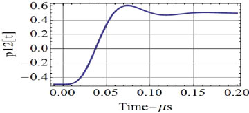
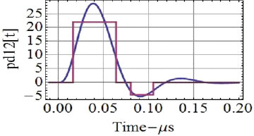
Figure 2 shows an example PN trapezoidal waveform and its derivative as a simple example of a filtered PN pulse punctual channel reference and the differentiated filtered pulse as the discriminator channel reference. It can easily be shown that the discriminator channel (not the discriminator output) is equivalent to an early-late DLL with a early-late separation equal to the rise time of the trapezoidal pulse. Figure 3 shows the discriminator channel and output.
FIGURE 2. Trapezoidal PN (1 Mcps) waveform pulse and its time derivative with a 0.1-microsecond rise time.
FIGURE 3. Discriminator channel, d[e], and (bottom) discriminator output, R[e] Rd[e], for the 1.0 Mcps PN with the optimum 0.1-microsecond reference and the 0.1-microsecond rise-time trapezoidal waveform.For comparison, Figure 4 shows the step response of a 4-pole Butterworth filter with a 12-MHz bandwidth and its derivative. We also show a two-step approximation to this analog step response, which can be used to optimize a weighted multiple early-late DLL or multiple correlator approximation to the QCDLL.
FIGURE 4. Step amplitude response and slope for a 4-pole Butterworth filter with a 3-dB bandwidth of 12 MHz (one-sided). The time derivative of this step response is shown on the lower plot along with a rectangular approximation.
Although not proven, the QCDLL appears to have several advantages in both noise and multipath performance as compared to the more conventional early-late gate (that I first presented in 1963):
The QCDLL discriminator channel reference is the differentiated pulse. Although for the trapezoidal pulse waveform, the conventional early-late DLL can in effect use the same discrimiantor reference if the early-late separation is set equal to the rise-time, for more general filtered waveforms, the early-late DLL can only approximate the optimal reference. Properly weighted multiple early-late DLLs offer a better approximation as shown in Figure 4, but still only an approximation.
The QCDLL discriminator output of Figure 3 is the product of the correlator channel and the discriminator channel. When tracking precisely, the correlator channel output is at its peak correlation. In contrast, a noncoherent early-late DLL only produces correlator outputs that are by definition early and late. Thus neither of these is at their peak, and the noise performance suffers accordingly. By the same token, the noncoherent early-late DLL discriminator output must be wider than that of the QCDLL, and the QCDLL multipath performance is improved in the same manner.
From a computational point of view, the early-late DLL is computing the small difference between two large numbers, namely the small difference between the ealy and late correlator channels. In contrast, the QCDLL is only computing the correlation of the received waveform with the narrow differentiated waveform used as the discriminator reference. For the simple example of the trapezoidal PN waveform, this reference is simply a narrrow time gate of width equal to the rise time.
Generalized BCS Techniques
My 2010 ION ITM paper, upon which this article is based, discusses a number of generalized symbol coding techniques including Neuman-Hofman, Barker, and Generalized Multiphase Barker, each of which provides minimal autocorrelation sidelobes. Various chirp-coded symbols with linear variation in chip-rate with time are analyzed and provide reduced sidelobes and spectral shaping. Rademacher and Walsh codes, time-multiplexed and properly weighted, form further generalizations. These can be time- or IQ-multiplexed, and the time-multiplexing can in turn be pseudorandomly permuted. In the limited space of this article we only discuss time-multiplexed (TM) Walsh Code symbols.
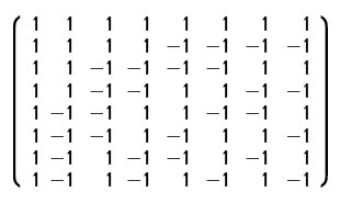
TM Walsh Codes. Walsh functions form a complete orthonormal set of binary functions of dimension 2n. Walsh codes are generated as products of Rademacher codes. There are 2n Walsh function of 2n binary elements. Thus a weighted sum of Walsh functions can approximate any discrete-time, time-limited waveform. Each PN symbol is coded with a Walsh code. Then time-multiplex two or more different Walsh-coded symbols in a sequential or time-weighted manner. We can then tailor the autocorrelation function and its sidelobes and spectra by using selected members of this set and appropriate weighting. The resulting combined autocorrelation function is then the sum or weighted sum of the individual autocorrelation functions, since we assume independence of the PN chips. The 8-dimensional binary Walsh codes (Walsh order) are the rows in the matrix:
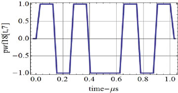
Figure 5 shows the trapezoidal filtered version of Walsh 7 for the dimension-8 Walsh functions.
FIGURE 5. Finite rise time trapezoidal Walsh coded symbol for Walsh code 7 with rise-time 0.03 microseconds and 1 Mcps.
Each Walsh sequence time multiplex modulates a separate and independent pseudorandom PN chip in sets of PN chips beginning from a PN epoch time; for example, the defined beginning of the PN sequence. Note that the equally weighted sum of all 8 Walsh functions is the vector {8,0,0,0,0,0,0,0}, which is equivalent to a single high-amplitude pulse of narrow width. Thus if we sum all of the Walsh functions, we obtain the equivalent of a single narrowband pulse where the autocorrelation sidelobes disappear. Even with filtering of the spreading waveform, the sidelobes can still be small. Likewise, the equally weighted sum of codes 5,6,7,8 is {4,4,0,0,0,0,0,0}, the Manchester code.
Since the Walsh functions form a complete orthonormal set, a weighted sum of Walsh functions can approximate any finite-duration signal of the same dimension, just as the Fourier series can approximate any periodic function. Thus a weighted sum of the Walsh functions in TM fashion can tailor the signal power spectral densities and autocorrelation functions to closely match a desired realizable function. Weighted TM BOC signals and Rademacher codes can also create useful approximations, but are not as general since they are not a complete orthonormal set.
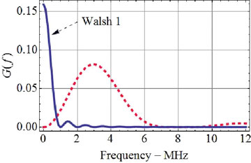
The spectrum and autocorrelation functions of the individual Walsh functions vary markedly from one another. Figure 6 shows two different selections of Walsh functions to illustrate an example of spectral separation. The wider-frequency spectra signal is a TM of Walsh codes 5, 6, 7, 8 and has improved autocorrelation with lower sidelobes compared to a single BOC signal. The lower-frequency spectrum represents the 0 Walsh, which is conventional PN.
FIGURE 6. Shaped power spectra for two TM trapezoidal Walsh signals.Blue solid curve Walsh 1, dashed curve TM Wash 5,6,7,8.
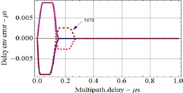
Figure 7 shows the multipath error envelope of the TM Walsh spreading waveform for TM of all 8 codes in comparison, with TM of 5,6,7,8 in the presence of multipath amplitude 0.5 versus multipath delay. These results for TM of all 8 Walsh correspond closely to that of PN waveform of 8 Mcps and rise time of 0.03 ❍s as expected.
FIGURE 7. Envelope of the multipath delay error when using the Walsh spreading function of dimension 8 and a trapezoidal signal rise time of 0.03 microseconds.
The envelope of the error increases as one would expect, to approximately 0.03-microsecond multipath delay. The solid blue curve is the result where all TM 8 Walsh codes are used. The dashed curve is for the TM 5,6,7,8 used to generate the spectral separation shown in Figure 6.
We can permute TM of Walsh functions and transmit each of these permutations in a pseudorandom sequence. There are 8! 5 40,320 different permutations of 8 Walsh functions. Thus we can use a different arrangement of the 40,320 patterns every 8 PN chips and do so with a different PN sequence to prevent a jammer from time-synchronizing the jammer spectrum to the Walsh multiplexing spectra with time. Weighted time-multiplexing can also be augmented with I/Q multiplexing. Pseudorandom permutation of the Walsh codes can also diminish spectral lines of the basic PN sequence if the two PN sequences are relatively prime.
Conclusions
This discussion first examines the QCDLL and its performance for conventional PN signals, and then generalizes the family of symbol coding/spreading techniques. The BOC signal, first called the split-spectrum signal, has a limited but important ability to shape the spectrum. It also increases its Gabor bandwidth and corresponding noise performance as indicated by the Cramer-Rao bound. However, the BOC signal has large autocorrelation sidelobes that when operating on both sidelobes simultaneously can cause limitations. There are BOC receivers which avoid that issue by operating separately on upper and lower frequency components. However, our focus is on more
general symbol-coding techniques that reduce autocorrelation sidelobes and provide good multipath performance.
The assisted QCDLL may improve performance as compared to the more conventional early-late non-coherent DLL in at least these respects:
The non-coherent early-late DLL autocorrelation is by definition offset by D/2 in the early–late DLL when locked rather than a perfect punctual channel.
The conventional early-late reference is not equal to the differentiated signal except for a trapezoidal signal with rise time of D/2.
The QCDLL uses an optimal reference for the discriminator channel.
The discriminator output of the QCDLL is the product of the punctual channel correlator with the discriminator channel, and thus has a narrower width than that of an early-late DLL and c better multipath performance.
The early-late DLL computes the small difference between two large correlator outputs, whereas the QCDLL computes that difference directly.
QCDLL performance in multipath is not claimed optimum; I and others have shown other techniques for reducing multipath by estimating and subtracting multipath components to reduce bias error on the direct signal. The results shown here with the trapezoidal wave-shapes may approximate the best performance possible, since the trapezoid has no precursor/tail that would be removed by a multipath-estimating receiver.
The optimal discriminator channel reference waveforms (the differentiated pulse waveform) defined for the QCDLL for any filtered received signal can be approximated by a sequence of pulses. These sequences of pulses define a quasi-optimal set of weighted conventional early-late DLL or multi-correlator tracking receiver configuration that approximate the optimal reference, the differentiated signal.
More general symbol coding techniques include: NH, Barker, generalized Barker, chirp, and TM Rademacher and Walsh codes. Barker, Generalized Barker, and NH codes have greatly reduced autocorrelation sidelobes and excellent multipath performance. These can also be time and I/Q multiplexed. Variants of chirp and TM Rademacher, Walsh can provide both spectral shaping and improved multipath performance. Weighted TM Walsh-coded symbols can be designed to synthesize any discrete-time, time-limited realizable function. Ordinary legacy PN can be time-multiplexed with any of these BCS symbols, with perhaps another longer PN sequence to generate a composite signal where a tracking receiver can operate on both simultaneously and yet leave legacy receivers still operational. Although we have only shown equal weighting in the TM multiplexing, clearly the weighting can be varied by changing the duty factor.
Acknowledgments
I wish to acknowledge the suggestions of Chris Hegarty of MITRE, J.K. Holmes, Aerospace Corporation, and Per Enge and Grace Gao, Stanford University. I give special recognition to Hegarty, Betz, and Saidi for their generalized BCS work on NH and Barker codes, and the thesis of J. A. A. Rodriguez, University FAF Munich, also on generalized BCS. The detailed version of this article appears in the 2010 ION International Technical Meeting Proceedings, and contains about 50 references.
James Spilker is a consulting professor in electrical engineering, aeronautics, and astronautics at Stanford, and co-author of Global Positioning System: Theory and Applications, Volumes I, II.
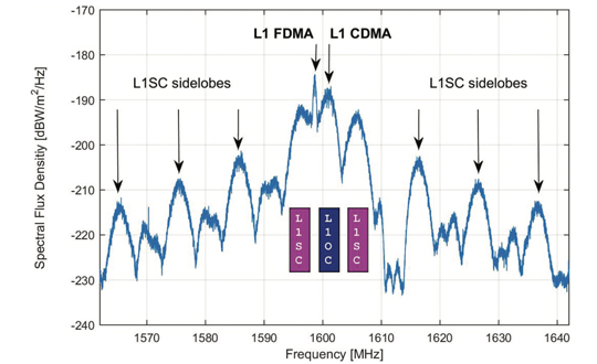
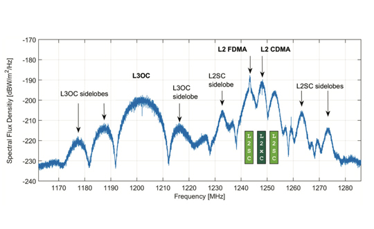
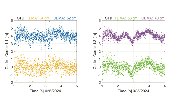
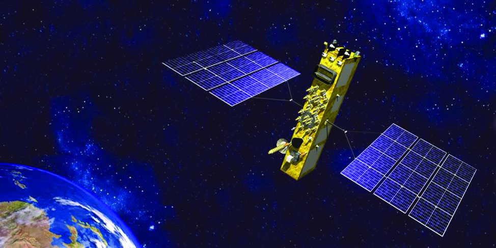
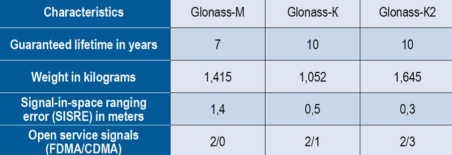
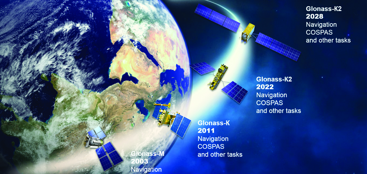


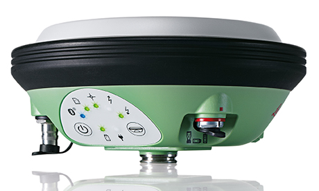

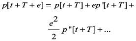
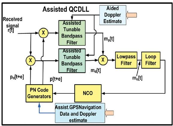
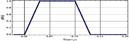
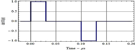 FIGURE 2. Trapezoidal PN (1 Mcps) waveform pulse and its time derivative with a 0.1-microsecond rise time.
![FIGURE 3. Discriminator channel, d[e], and (bottom) discriminator output, R[e] Rd[e], for the 1.0 Mcps PN with the optimum 0.1-microsecond reference and the 0.1-microsecond rise-time trapezoidal waveform.](https://stage.globalpositioningnews.com/wp-content/uploads/2010/05/EA-3.jpg)