GLONASS satellites traditionally use L1 and L2 frequency division multiple access (FDMA) signals. FDMA is characterized by a different transmit frequency for each satellite. Newer satellite generations also transmit an L3 code division multiple access (CDMA) signal. CDMA uses the same frequency but different ranging codes for individual satellites. The first GLONASS K2 satellite, with the space vehicle number R803, was launched in August 2023. It extends the range of CDMA signals to the L1 and L2 bands.
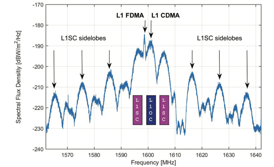
Figure 1. GLONASS K2 spectrum of the L1 frequency band. The different components of the L1 CDMA signal are indicated by colored boxes. L1SC: secured signal. L1OC: open service signal. (All figures provided by the authors)
Frequency spectra of R803, including these new signals, are shown in Figures 1 and 2. They were measured with the 30 m high-gain antenna of the German Space Operations Center (GSOC) in Weilheim, Germany, on Jan. 17, 2024. The largest and sharpest peak in the L1 band at 1,598.625 MHz originates from the 0.5 MHz binary phase-shift keying (BPSK) FDMA signal. The center peak of the L1 CDMA signal is located at 1,600.995 MHz. It is related to the L1 open service signal consisting of a data component (L1OCd) and a pilot component (L1OCp). L1OCd and L1OCp are combined by time-division multiplexing. The peaks that are ±5 MHz away from the L1 CDMA center frequency are introduced by the binary offset carrier (BOC) modulation of the secured L1SC signal. Prominent L1SC side lobes are visible ±15, ±25 and ±35 MHz offset from the center frequency. A quadrature phase-shift keying (QPSK) modulation is used to combine the L1OC and L1SC signals. The local minimum between 1,610 MHz and 1,614 MHz is caused by a notch filter onboard the satellite to protect radio astronomical observations of the Hydroxyl spectral line at 1,612 MHz.
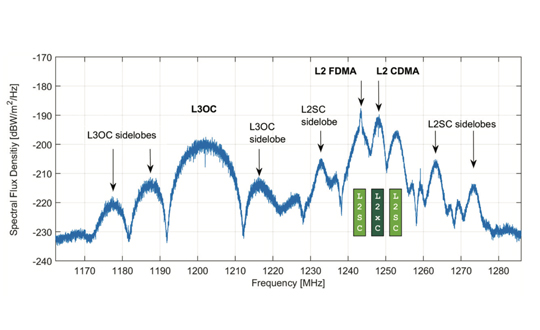
Figure 2. GLONASS K2 spectrum of the L2 and L3 frequency bands. The different components of the L2 CDMA signal are indicated by colored boxes. L2SC: secured signal. L2xC stands for the time multiplexed L2OCp and L2 CSI signal. (All figures provided by the authors)
The L2 CDMA signal is composed of a signal for service information (L2 CSI) and the pilot open service navigation signal (L2OCp). As for L1, these two signals are time-division multiplexed and combined with the secured L2SC signal by QPSK. The left main lobe of the L2SC signals coincides with the L2 FDMA center frequency of 1,243.375 MHz. Both, the L2 CSI, as well as the L2OCp signal, contribute to the peak at the L2 CDMA center frequency at 1,248.06 MHz. The L3 CDMA signal is composed of 10 MHz BPSK data (L3OCd) and pilot (L3OCp) components resulting in a broad peak at 1,202.025 MHz.
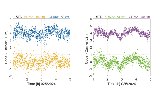
FDMA and CDMA signals of GLONASS R803 were tracked with a JAVAD TRE_3S receiver with a prototype firmware located at GSOC in Oberpfaffenhofen, Germany. Figure 3 shows the differences between pseudo range and carrier phase observations for the FDMA and CDMA signals in the L1 and L2 frequency bands. Long-term ionospheric effects were removed by a second-order polynomial. Thus, remaining effects include short-term ionospheric variations, multipath, and observation noise. The standard deviation of the code–carrier combination is, in general, at the half-meter level. Due to their advanced design, the CDMA signals show an improved performance by 18% for L1 and even 31% for L2 compared to the legacy FDMA signals.
Figure 3. Code – carrier for GLONASS R803 FDMA and CDMA signals: L1 (left) and L2 (right). A second order polynomial has been removed and the CDMA signals are shifted by 4 m. (All figures provided by the authors)
Further launches of L1 and L2 CDMA-capable GLONASS K2 satellites are planned for the upcoming years. A constellation of at least 12 satellites is expected for 2030. To guarantee backwards compatibility, these satellites will also transmit the L1 and L2 FDMA signals. Further improvements in positioning accuracy are expected due to improved satellite clocks and inter-satellite laser ranging.
Russian Space Systems (2016), GLONASS Interface Control Document: Code Division Multiple Access Open Service Navigation Signal in L1 frequency band. Russian Rocket and Space Engineering and Information Systems Corporation, Joint Stock Company.
Russian Space Systems (2016), GLONASS Interface Control Document: Code Division Multiple Access Open Service Navigation Signal in L2 frequency band. Russian Rocket and Space Engineering and Information Systems Corporation, Joint Stock Company.
Manufacturers
GNSS data used in this article were collected with a JAVAD TRE_3S receiver. The spectral overviews were captured with a Rohde & Schwarz FSQ26 signal analyzer.
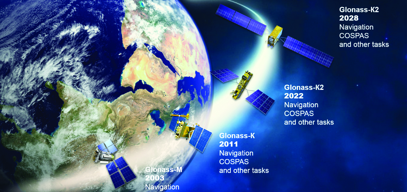
On Nov. 29, 2022, Russia launched the 51st Glonass-M satellite, completing a 20-year history that began on Dec. 10, 2003, with the launch of the first one. These satellites have been providing navigation signals in two frequency bands, L1OF and L2OF, to civil users since 2011.The average orbit lifetime for this type of satellite is more than 10 years, and 13 Glonass-M satellites operate beyond their guaranteed lifetime. The last set of seven satellites has been broadcasting the first CDMA civil signal, L3OC, by means of an additional antenna and onboard transmitter.
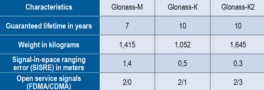
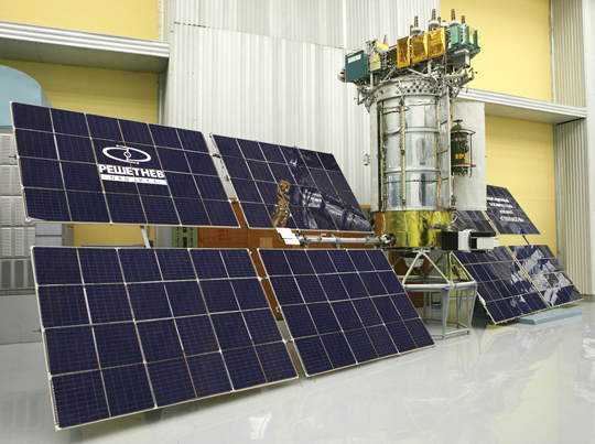
Starting this year, the constellation will be renewed by Glonass-K and Glonass-K2 satellites, which provide CDMA signals to users. Furthermore, four Glonass-K satellites will be supplemented with additional Glonass-K satellites and the first Glonass-K2 satellite. The K2 satellite has passed all ground tests and is ready to be transported to the launch site (Figure 1). Table 1 lists the technical characteristics of GLONASS satellites.
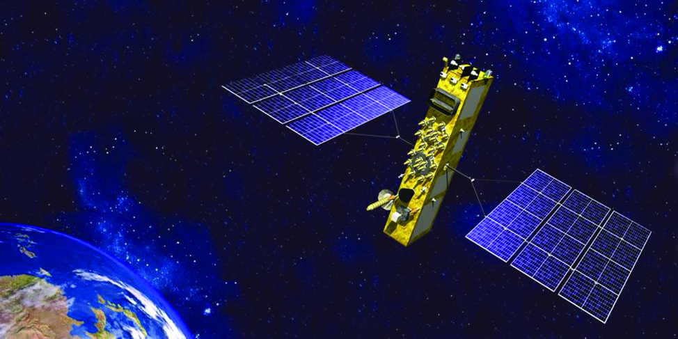
Figure 1. Artist’s rendition of the Glonass-K2 satellite in orbit.Table 1. The evolutions of GLONASS satellites.
The distinguishing feature of this satellite’s design is its two antenna arrays — one for CDMA signals with phase centers on the geometrical axis of the satellite, and the second for FDMA signals with phase centers shifted by 0.9 m relative to that axis.
The optical reflector panel center is also located on the satellite’s geometrical axis and passed through its mass center. It seems to be a very interesting scientific task to estimate the satellite flight model parameters by International Laser Ranging Service stations with the objective to improve the accuracy of the navigation signals for both antenna arrays.
Future GLONASS satellites will have a single antenna array for CDMA and FDMA signals (see Figure 2).
Figure 2. The evaluations of GLONASS satellites.
For analogous updates on the other three GNSS constellations, please see:
Yury Urlichich, First Deputy Director General, Roscosmos. (Photo: Roscosmos)
By Yury Urlichich, First Deputy Director General of ROSCOMOS State Space Corporation Sergey Karutin, Designer General of GLONASS Nikolay Testoedov, Director General, Information Satellite Systems
Roscosmos keeps concentrating on user needs as it did in previous years. Growing digitalization is driving a high demand for high-accuracy navigation services. Space information technologies support user needs by modern digital services, including increasing accuracy of position and velocity determination. Because of this, it is of vital importance for us to ensure that GLONASS provides continuous services and stable performance.
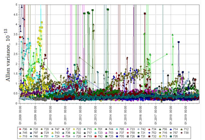
Figure 1. Mature Glonass-M satellites show improved cesium frequency standards performance in terms of daily stability. (Image: Roscosmos)
Performance Standard & ICD
This year, we finished drafting the GLONASS Open Service Performance Standard (GLONASS OS PS; the Russian language version is available). In 2020, the new version of the GLONASS Interface Control Document (ICD) also will be publicly available.
GLONASS OS PS serves as a high-level mainframe document specifying the values of the achieved GLONASS performance characteristics plus the significant guaranteed margin. These, coupled with the signal reception environment and a priori estimation of user equipment performance characteristics, can further be translated into the performance that an end user can expect to achieve in his specific PVT solution.
This GLONASS OS PS is a basis for certification of GLONASS services and development of lower level standards for user receiver and GLONASS-based service, as well as for development of international standards like those of the International Civil Aviation Organization (ICAO), the International Maritime Organization (IMO) and others.
Use of the unified set of performance parameters and calculation methods for all GNSS — GLONASS, GPS, Galileo and BDS — is a conventional practice. The similar standards for GPS, Galileo and BDS have been published and are regularly updated.
In fact, this GLONASS OS PS is the second one after the ICD baseline interface between GLONASS and user receiver manufacturers and the GLONASS-based services developers. The OS PS establishes the minimum performance that can be achieved by users with a high level of trust based on the system’s long-term statistical history.
Signal-in-Space. This OS PS specifies standards for the GLONASS OS Signal-in-Space (SIS) performance neglecting receiver biases, signal propagation and reception biases (in terms of performance metrics used to specify system performance, that is, taking into account the GLONASS space segment and the GLONASS ground segment contributions to the performance). It can serve as a basis for certification of the GLONASS-based services and receivers incorporating GLONASS, including those used in aviation and other user domains.
The OS PS provides an overview of the GLONASS system and an overview of the GLONASS Open Service SIS. It specifies the standards for the performance characteristics of the channel of standard accuracy used to provide the Open Service, and lists the legal reference documents.
L3 CDMA. One of the most significant tasks is the harmonization of GLONASS user interfaces with respect to new L3 CDMA signals. The requirements related to the interface between the space segment of GLONASS and the navigation user segment for radio frequency links is established by the GLONASS ICDs.
The new version of ICD for CDMA L1, L2 and L3 signals to be broadcast by new-generation Glonass-K2 satellites was issued in 2016. However, the Glonass-M satellites (## 755-758) and the Glonass-K satellites currently in orbit transmit the L3 signal as per the L3 Open Access CDMA Radionavigation Signal Interface Control Document (Edition 1) of 2011.
In order to mitigate the above-mentioned discrepancies, five reference documents (Interface Control Documents for open-access signals) have been updated and prepared for publication. In addition, flight tests to verify new ionospheric and tropospheric delay models have been scheduled.
Incorporating More Data
The new ICDs for open access and authorized signals incorporate changes related to the introduction of additional data into the spare bits of the navigation message. This additional data is to be used by user receivers for better PVT solution purposes.
The updated versions of ICDs will incorporate:
The mathematical ionospheric delay model and inclusion of the model parameter into the navigation message.
The mathematical tropospheric delay model, which does not require that any specific parameters be included into the navigation message. It only employs data on the latitude of a user receiver location and the season (i.e., winter, spring, summer, and autumn).
The attribute (or flag) to inform a user that a satellite is in the turn mode and its antenna phase center behavior is different from that when a satellite is in the sun orientation mode.
Information about the types of signals broadcast on the L1, L2, and L3 frequencies; 5-bit field, in which the first three bits denote L1, L2, and L3 CDMA signals, respectively, while the 4th and the 5th bits denote L1 and L2 FDMA signals, respectively.
A 5-bit field to be used to broadcast age of data (AOD) for time offsets in addition to the similar field used to broadcast AOD for ephemerides.
Backward Compatibility. The updated CDMA and FDMA ICDs will support the backward compatibility for the uninterrupted operation of the existing envelope of user equipment and the introduction of the ionospheric and tropospheric model parameters into the message spare capacity.
Constellation Refresh
The GLONASS constellation has been replenished steadily. Since 2013, we have been launching one to two satellites a year, and this year is not an exception. The launch on May 27 and the December launch will help sustain the nominal constellation. The Glonass-M satellites demonstrate good dynamics for the average operational life. Two satellites are well beyond their 10-year design life — their operational lifetime has exceeded 12 years. As some of the Glonass-M satellites grow older, their cesium frequency standards performance in terms of daily stability improves (see Figure 1).
Glonass-K. In 2020, the launch campaign for the Glonass-M satellites will come to its end. The Glonass-K satellites will come on stage with the first launch of Glonass-K-15 scheduled for the beginning of the next year. We are fully confident that this satellite will not disappoint our users.
By Sergey Karutin, GLONASS designer general; Nicolay Testoedov, Director General, SC Information Satellite Systems; and Andrey Tulin, Director General, SC Russian Space Systems
This year has marked the 35th anniversary of the first GLONASS launch. During these years, the world has made great strides through high tech, and now no modern society can progress without satellite-based navigation.
Today’s urban resident can hardly do without a smartphone planning his route through traffic, determining the paid parking site location or getting a reminder of parking session completion once he has left the parking lot.
The search for the nearest pharmacy, gas station, restaurant or any other point of interest is of vital necessity today. The growing dependence of modern society on navigation signals-in-space increases the responsibilities of GNSS providers. At the same time, users long for simplicity in getting quality services. That is why this year the GLONASS team is going to set up its most ambitious program: improving the quality of the GLONASS services at a user level.
The traditional GLONASS conception of signal-in-space accuracy is now being augmented by the user level performance estimation. Due to the fact that the signal propagation environment contributes a lot to the positioning error budget, it is obvious that users need information that would reduce the influence of signal propagation path on the positioning accuracy.
Glonass-M satellites currently form the core of the GLONASS constellation, and with six ground spares now in stock, they will continue to do so for at least the next eight years. Therefore, in 2018 the new edition of L1 and L2 FDMA Interface Control Documents are to be published which will include the ionospheric and tropospheric models recommended in the recently released GLONASS CDMA Signals ICDs.
Glonass-K2 satellite (artist’s rendering).
We plan to use the spare bits within the navigation superframe of FDMA signals to transmit ionospheric parameters described in the General Description of the GLObal NAvigation Satellite System with the Code Division Multiple Access Signals ICD.
Studies being performed demonstrate up to 70 percent reduction in impact of ionospheric refraction when using the adaptive model transmitted by the three parameters: the numerical factor for the peak TEC (Total Electron Content) of F2 ionosphere layer, the solar activity index and the daily geomagnetic activity index. In the new CDMA signal message, these parameters are initially provided.
To enable the unanimity of technologies for reducing the hydrostatic component of the tropospheric delay, which accounts for 80 percent of its value, the both FDMA and CDMA Signals ICDs will include the latitudinal tropospheric model based on the preliminary set tabular values.
The preliminary design review for the technical baseline of the fourth-generation Glonass-K2 satellite has been passed this year. The new cubic arrangement of the platform enables mitigation of unmodeled forces and transition of propellant tank to the satellite’s center of mass.
This provides for the relative position constancy for the satellite’s center of mass and the satellite’s antenna phase center during the satellite’s lifetime. This platform arrangement also accommodates the whole ensemble of navigation signals (both CDMA and FDMA) on the single phased-array antenna system.
Glonass-K2 is equipped with the new atomic frequency standard composed of the legacy quantum frequency standard based on the cesium beam tube and the passive hydrogen maser. The miniature PHM with the relative daily stability of 5×10-15 will be installed onboard the satellite to be launched in 2020.
Introduction of the new satellite will enable a new constellation sustainment strategy — through the both dual launches by Angara-A5 launcher from Vostochny and single launches by Soyuz from Plesetsk — to provide on-demand replenishment of the constellation.
By 2020, when we celebrate the 25th anniversary of GLONASS full operational capability, all the efforts mentioned above will offer new quality of services to GLONASS users prioritized as per their needs.
By Yuri Urlichich, Valery Subbotin, Grigory Stupak, Vyacheslav Dvorkin, Alexander Povalyaev, Sergey Karutin, and Rudolf Bakitko, Russian Space Systems
The GLONASS-K satellite, transmitting a CDMA signal in the L3 band, inaugurates a new era of radionavigation signals for both the Russian system and for international GNSS interoperability. As demand for high-precision services through dual- or triple-frequency user equipment increases, GLONASS will come to the forefront. The 2014 GLONASS-K2 satellite will have an FDMA signal in the L1 and L2 bands and CDMA signals in L1, L2, and L3. The overall constellation update will be completed in 2021. Another 2014 launch will fill the Russian SBAS orbit constellation with three geostationary space vehicles.
GLONASS-M satellite. (Photos courtesy of Roscosmos and Information Satellite Systems Reshetnev Company)GLONASS-K satellite. (Photos courtesy of Roscosmos and Information Satellite Systems Reshetnev Company).
With the February launch of the first GLONASS-K satellite, and its transmission of a new CDMA signal in the L3 band, a new era of radionavigation signals has begun: international GNSS interoperability. As we have seen rapidly growing demand for high-precision services provided with dual- or triple-frequency user equipment, introduction of new GLONASS signals in the L1 and L2 bands will come next. The first launch of GLONASS-K2 satellite, with FDMA signals in L1 and L2 bands and CDMA signals in L1, L2, and L3, is planned in 2014. A complete update of the full orbiting constellation will conclude in 2021.
One satellite per year of the Luch family will be launched into orbit over the next three years, and by 2014 the System of Differential Correction and Monitoring (SDCM) constellation will be in operation with three geostationary space vehicles.
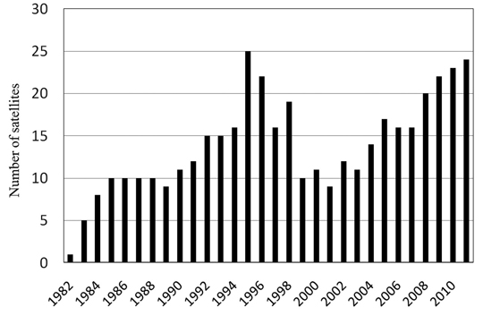
Constellation Status. In spite of the unsuccessful launch of three satellites at the end of 2010, currently GLONASS is fully deployed again with 23 satellites set healthy to the user, and more in orbiting reserve. Figure 1 shows the evolution of the constellation since its first launch in 1982. The number of satellites used for service provision is calculated at the end of each year. In order to avoid dramatic situation in 1996–2000, when satellite numbers fell, the system now carries both an on-orbit and a ground reserve of space vehciles. This will help avoid service and availability gaps that could be created by satellite failure.
Figure 1. GLONASS constellation development.
GLONASS-M. The current constellation consists largely of GLONASS-M satellites, the first generation of GLONASS space vehicles, with characteristics of:
FDMA сivil signals in L1 (1.6 GHz) and L2 (1.25 GHz) bands, with increased transmitting power;
intersatellite link both inside one plane and between planes with ranging and communication capabilities;
relative daily frequency stability of the cesium onboard synchronizer of 5 × 10–14;
increased orientation accuracy of solar panels;
guaranteed active lifetime of seven years.
New satellites can be launched into orbit either as a part of multiple launch consisting of three satellites on the launch vehicle Proton with booster Breeze-M from the Baikonur spaceport, or on the launch vehicle Soyuz with Fregat booster from Plesetsk.
GLONASS-M is the last GLONASS satellite with its payload in a sealed container. This container provides the high-temperature stability for the onboard clocks. The GLONASS-M power-supply system includes nickel-hydrogen batteries and silicon solar arrays of 30 square meters, providing 1,400 W for onboard systems.
GLONASS-K. Currently, on-orbit flight tests of the new GLONASS-K satellite (OPENING PHOTO) are under way. The first satellite in the GLONASS-K family, it has a payload located in open space and an active lifespan of 10 years. The forming and transmitting functions of navigation and inter-satellite signals are united in one module in order to increase synchronization accuracy. Besides broadcasting radionavigation signals in three bands, this satellite carries the transponder of the search-and-rescue system COSPAS-SARSAT. The overall weight of the satellite is less than 1,000 kilograms, and about 30 percent of this is the payload weight. The power-supply system generates about two times more energy than the same GLONASS-M system.
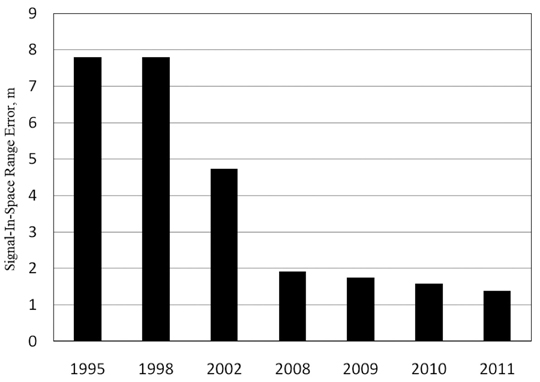
At the same time, ground-control facilities modernization and implementation of new inter-satellite measurement technology has enabled system operators to effectively increase the accuracy of broadcast ephemeris and clocks. Currently the signal-in-space range error (SISRE) equals 1.37 m (Figure 2). Further increases in accuracy will be carried out through the modernization of satellite-control technologies and development of a global network of measuring tools.
Since February 2011, GLONASS-K has been transmitting the first CDMA navigation signal in L3 band coherently with existing L1 and L2 signals. This was a first step in a new navigation signal development strategy. Future steps of GLONASS CDMA navigation signal development will focus on L1 and L2 bands. In order to design user-friendly signals, the following assumptions have been taken into account:
GLONASS coherent FDMA and CDMA navigation signal sets should satisfy a wide range of user requirements, from ordinary navigation to high-precision applications;
Signals should be within the bands allocated for GLONASS by the International Telecommunications Union (ITU);
Low spectral density of signal power in radio astronomical band of 1610.6-1613.8 MHz;
Compatibility with other GNSSs;
Interoperability with other GNSSs.
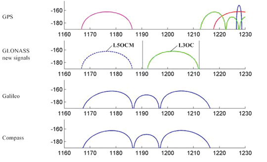
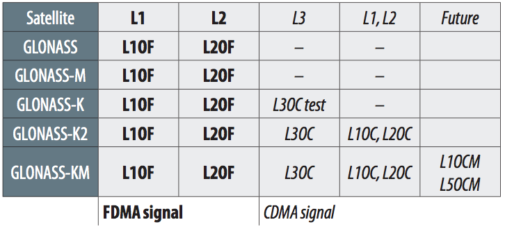
The plans for signal development with GLONASS code division are presented in Table 1.
Table 1. FDMA (in bold type) and CDMA (in slant type) signals in current and future GLONASS satellite generations.
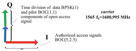
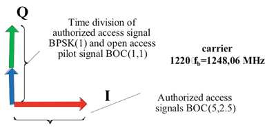
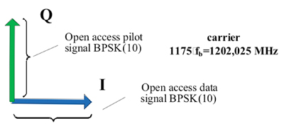
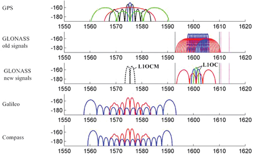
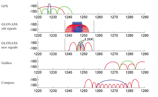
Figures 3–8 show the proposed structures of GLONASS CDMA signals and also the spectrums of these signals in the context of the other GNSS signal spectrums.
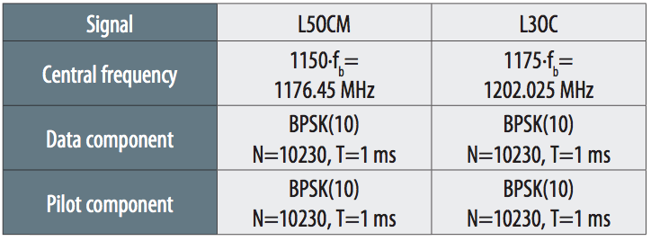
Due to the growing use of GNSS signals in L3/L5 band, the future GLONASS navigation family will include two signals in this band. Table 2 contains some parameters of these new signals in this band.
Table 2.
GLONASS Augmentation Development
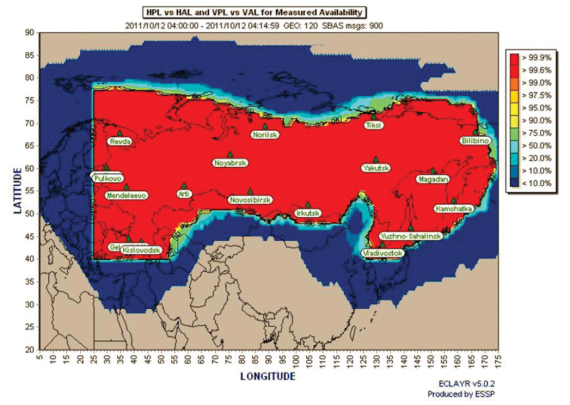
SDCM development is now entering its deployment and completion phase. The network of reference stations is almost completely established. It enables the global integrity monitoring of radio navigation signals of both GLONASS and GPS satellites, gathering raw measurements of pseudorange and carrier phase in L1, L2, and L3/L5 bands. Based on these measurements, the SDCM central processing facility calculates orbits and clock corrections, and formulates SBAS messages. Preliminary results of SDCM service-quality estimation, based on corrections calculated using existing stations network, are shown in Figure 10.
Figure 10. SDCM horizontal protection Level (HPL) versus horizontal alert limit (HAL). Image updated April 16, 2012.
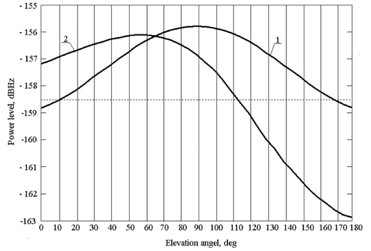
The last quarter of 2011 will see the launch of space vehicle (SV) Luch-5А, carrying an SDCM transponder. Initially, this SV will be put for testing on geostationary orbit at 55 degrees East, and then will be relocated to 16 degrees West. The onboard transponder will broadcast radio signals on 1575.42 MHz. Taking into account that the main SDCM coverage area is in the northern hemisphere, the SV antenna beam will be deviated from the Equator by 7 degrees to the north.
Due to this deviation of the gain pattern from traditional orientation to the Equator, the Earth surface power distribution diagram is changed. Figure 11 presents two variants. The first one is a case in which the transmission antenna is directed on the Equator (curve 1) and the second one is a case when antenna is deviated by 7 degrees to the north from equator (curve 2). In the latter case, we obtain an increase of signal strength to the users for which this SV is under small elevation angles, that is, for the users in the northern areas of the Russian Federation.
Figure 11. SDCM minimum user-received signal levels: (1) antenna pointing to the equator; (2) antenna deviated by 7º to the north.
Further SDCM development is predicated upon the launch of two Luch satellites, in the first half of 2012 and in 2013, respectively. Also in the plans is the design of a new Luch-4 satellite with dual-frequency navigation transponder, for a 2014 launch, completing the satellite-based augmentation system.
Conclusion
GLONASS system replenishment has almost finished, and the system enters a new historical phase. New CDMA navigation signals and deployment of a national SBAS system will provide not only a significant quality improvement of GLONASS navigation services, but also will create the favorable prerequisite for the development of applied navigation technologies in the territory of the Russian Federation, and also in Europe, the Middle East, and the Far East.
Yuri Urlichich is a general director-general designer of Joint Stock Company (JSC) Russian Space Systems, GLONASS general designer, doctor of science, professor, author of more than 150 papers and holder of 20 patents.
Valery Subbotin is a first deputy general director–general designer of JSC Russian Space Systems, and doctor of science. He has been working in the space industry for more than 40 years and has published more than 50 papers.GRigory Stupak is a deputy general director–general designer of JSC Russian Space Systems, deputy general designer of GLONASS, and professor at the Bauman Moscow State Technical University (BMSTU). He has worked in the space industry more than 35 years and has published more than 150 papers.
Vyacheslav Dvorkin is a deputy general designer of JSC Russian Space Systems”and doctor of science. He has been developing GLONASS, GNSS augmentations and user equipment for more than 35 years. He has written 50 papers in the satellite navigation field.
Alexander Povalyaev is a deputy head of division in JSC Russian Space Systems and professor at the Moscow Aviation Institute. He has been developing methods and algorithms for GNSS carrier-phase measurements processing for more than 30 years and has more than 40 papers in satellite navigation field.
Sergey Karutin is deputy head of division in JSC Russian Space Systems and assistant professor at the BMSTU. He has a Ph.D. and has been working on the GLONASS team since 1998, developing GNSS augmentations and user equipment.
Rudolf BAKITKO is a department head in JSC Russian Space Systems and a GLONASS navigation payload designer. Rudolf developed on-board equipment for space vehicles Luna, Mars, Venus, GLONASS, and COSPAS-SARSAT, and has more than 50 papers and 10 patents.