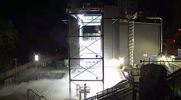
The Ariane 6 launch vehicle program has taken a dramatic step towards first flight with the start on Oct. 5 of hot-fire tests of the rocket’s upper stage and its all-new Vinci engine, according to the European Space Agency (ESA).
The tests are a significant step forward. They are being conducted using the specially built P5.2 test bench for engine and stage testing at the German Aerospace Center (DLR) in Lampoldshausen. The P5.2 test bench subjects the entire upper stage to operating conditions representative of a flight from Europe’s Spaceport in French Guiana, with the exception of vacuum and microgravity.
New Vinci Engine
Vinci, the upper stage engine of Ariane 6 fed by liquid hydrogen and oxygen, can be stopped and restarted multiple times — a critical capability for the complex missions demanded by launch customers today.
The rocket can place several satellites into different orbits and de-orbit the upper stage, leaving a minimum of hazardous debris in space. Vinci also has been developed for reliability, simplicity and lower costs.
Replacement Heavy Launcher
This test series is a critical milestone on a development path that will soon see Ariane 6 replace Ariane 5 as ESA’s heavy launcher.
For more than a quarter century, Ariane 5 has been a reliable partner for commercial, institutional and scientific clients. One of its most notable missions was the Dec. 25, 2021, flight that carried the NASA/ESA/CSA James Webb Space Telescope to its operational outpost in deep space.
But Ariane 6 will be an even more versatile vehicle, strengthening Europe’s autonomy in accessing space.
Auxiliary Power Unit
The tests being run at Lampoldshausen are also evaluating an innovative auxiliary power unit (APU) that works in tandem with the Vinci engine and is instrumental to Ariane 6 upper-stage performance.
To restart in space, earlier engines relied on large quantities of tanked helium to generate the necessary pressure and temperature in the propellant tanks and to ensure there are no bubbles in the fuel lines. However, the APU delivers these conditions using only small amounts of the cryogenic hydrogen and oxygen already carried in the main tanks.
Heading to ESTEC
The test series is being run by DLR and ArianeGroup, the Ariane 6 launcher prime contractor. When the test series is complete, the upper stage — integrated by ArianeGroup at its facility in Bremen, Germany — will be shipped to ESA’s ESTEC technical center in the Netherlands for stage separation and acoustic tests.
Ultimately, the Lampoldshausen tests will investigate hardware behavior and system function of the complete stage with its tanks, engines and avionics.
“The preparation for these hot firing tests is even more complex than for an actual launch,” said Ariane 6 launcher program manager Guy Pilchen. “Our colleagues in Lampoldshausen have decades of experience in rocket propulsion with extremely advanced test facilities. With ArianeGroup colleagues to control the upper stage and DLR people operating the test bench, we couldn’t ask for a better team.”
Space independence for Europe
ESA Director of Space Transportation Daniel Neuenschwander said that this new engine and the upper stage it powers are indispensable components of Ariane 6 and its objective — to guarantee that Europe maintains independent, competitive and sustainable access to space.
“It’s a fact in the 21st century that Europeans depend on space for safety, prosperity and security,” Neuenschwander said. “Europe needs to work toward complete autonomy in accessing and operating in space. Ariane 6 is key to this, and we are eager to see the liftoff from Europe’s Spaceport in French Guiana.”
Ariane 6 Vinci engine testing at DLR Lampoldshausen. (Photo: ESA)
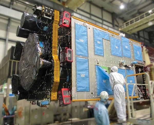
QZS-R1 is prepped for testing. At left is the Earth-oriented surface that hosts the L-band antenna. (Photo: JAXA)
By Peter Steigenberger, Steffen Thoelert, Sergei Yudanov and Markus Ramatschi
The Japanese QZS-1R satellite was launched on Oct. 26, 2021, from the Tanegashima Space Center in Japan. It serves as a replenishment for QZS-1, the first spacecraft of the Japanese Quasi-Zenith Satellite System (QZSS) in orbit since September 2010.
QZS-1R joins the current QZSS constellation of three satellites in inclined geosynchronous orbit (IGSO) and one geostationary satellite. These four Block I satellites transmit the L1C/A signal at 1575.42 MHz.
QZS-1R, as well as future QZSS satellites, are able to transmit the new L1C/B signal. L1C/B is based on the same family of gold codes as L1C/A, but uses a binary offset carrier (BOC) modulation instead of the binary phase-shift keying (BPSK) and a different PRN range (203–206).
Compared to BPSK, the BOC modulation adds a square wave subcarrier with a frequency of fsc = 1.023 MHz that equals the chipping rate of the ranging code. This subcarrier shifts the peak spectral energy from the center frequency fL1 to fL1 ± fsc to reduce interference with the GPS L1C/A signals.
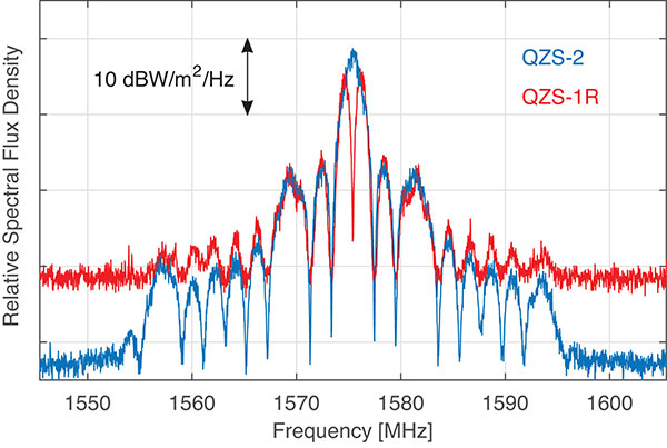
During in-orbit testing (IOT) from late November until early December 2021, QZS-1R transmitted L1C/A and L1C/B signals intermittently. FIGURE 1 shows a spectrum of the L1-band transmissions of QZS-1R recorded on Nov. 25 with the 30-meter dish antenna of the German Space Operations Center in Weilheim, Germany, as well as a spectrum of QZS-2 recorded in July 2017.
Figure 1. L1 spectra of QZS-1R (red) transmitting L1C/B and L1C, as well as QZS-2 (blue) transmitting L1C/A and L1C. The spectra were measured with DLR’s 30-meter high-gain antenna on Nov. 25, 2021, and July 20, 2017, respectively. (Credit: DLR)
During IOT, QZS-1R had an extremely low maximum elevation of 0.8° in Weilheim. Due to technical restrictions for such low elevations, QZS-1R had to be observed with a sidelobe of the 30-meter antenna. As a result, the respective observations are much more noisy than the QZS-2 reference data.
Nevertheless, the different spectral characteristics of L1C/B and L1C/A can be clearly seen in FIGURE 1: L1C/B has two maxima at 1574.4 and 1576.5 MHz due to the BOC modulation, whereas the BPSK L1C/A signal has one maximum at the center frequency of 1575.42 MHz.
GNSS receivers of the International GNSS Service (IGS) started to track L1C/A, L1C, L2C and L5 signals of QZS-1R on Nov. 17. Aside from the regular PRN code J04, test signals using the non-standard code PRN J06 were intermittently transmitted by QZS-1R during the IOT and tracked by these receivers.
Based on the public specification of the new L1C/B signal, Javad GNSS developed a prototype firmware that enabled tracking of this signal during the early transmissions. This firmware was installed on a Javad TRE-3 receiver operated by GFZ German Research Centre for Geosciences at its IGS station WUH200CHN in Wuhan, China.
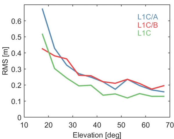
FIGURE 2 illustrates the noise and multipath characteristics of different QZS-1R pseudorange measurements. It is based on the so-called multipath linear combination of L1 pseudorange and L1/L2 carrier-phase observations covering a six-hour data arc. RMS values were computed for 5-degree elevation bins for each pseudorange signal. While the individual signals were tracked on different days of the IOT and the associated results have to be interpreted with care, the data indicate a very similar ranging performance of the legacy C/A signal and the new C/B signal. Best results are obtained with the L1C signal, which uses both a higher signal power and an advanced modulation with superior multipath suppression.
Figure 2. Noise and multipath characteristics of QZS-1R signals on the L1 frequency tracked by the IGS station WUH200CHN in Wuhan, China. (Credit: DLR)
QZS-1R will resume continuous transmission of L1C/A as soon as declared healthy. The transition from L1C/A to L1C/B is planned for 2023-2024, when an operational QZSS constellation of seven satellites is reached. The launches of the IGSO satellite QZS-5, the geostationary QZS-6, and the quasi-geostationary QZS-7 are all planned for 2023.
GNSS data used in this article were collected with a Javad GNSS TRE-3 receiver. The spectral overviews were captured with a Rohde & Schwarz FSQ26 signal analyzer.
Peter Steigenberger is a senior scientist at the German Space Operations Center of the German Aerospace Center (DLR), where he conducts research in the field of new satellite navigation systems.
Steffen Thoelert is an electrical engineer at DLR’s Institute of Communications and Navigation. His research activities focus on signal-quality monitoring and satellite payload characterization.
Sergei Yudanov is a senior firmware developer at Javad GNSS, Moscow. His main field of activity is GNSS signal processing.
Markus Ramatschi is a senior scientist at the Helmholtz Centre Potsdam, GFZ German Research Centre for Geoscience. He is operating a global GNSS reference station network.
Ramatschi M., Bradke M., Nischan T., Männel B. (2019): “GNSS data of the global GFZ tracking network,” vol 1. GFZ Data Services. https://doi.org/10.5880/GFZ.1.1.2020.001
By Brandon Weaver, Gianluca Zampieri and Okuary Osechas
Innovation Insights with Richard Langley
IT’S A FACT. GPS and its brethren global (and regional) navigation satellite systems are susceptible to outages caused by both natural and engineered events. Several reports issued in the past couple of decades have documented the vulnerability of GNSS. Twenty years ago this past August, the U.S. Department of Transportation’s John A. Volpe National Transportation Systems Center issued a report, commonly referred to as the Volpe Report, in which they found that “GPS service is susceptible to unintentional disruptions from ionospheric effects, blockage from buildings, and interference from narrow and wideband sources.” Although not explicitly mentioned in the report, besides emissions from communications systems, wideband interference can come from solar radio noise storms overpowering GPS signals. The report also highlighted that the “GPS signal is subject to degradation and loss through attacks by hostile interests. Potential attacks cover the range from jamming and spoofing of GPS signals to disruption of GPS ground stations and satellites.”
The Volpe Report recommended a number of actions to mitigate the vulnerabilities of the GPS signal to disruption or loss, including the need for backups for positioning, navigation and timing — particularly for GPS applications involving the potential for life-threatening situations such as the loss of GPS use for safety-of-life navigation, which would include, for example, aircraft navigation.
With the introduction of GPS (and subsequently the other GNSS and their augmentations) and its widespread adoption by the aviation industry, legacy navigation systems such as Omega, aviation radiobeacons, VHF Omnidirectional Range (VOR) and Distance Measuring Equipment (DME), were either shut down, reduced in their number of installations, or displaced as the primary method of navigation. These systems could not offer the same capabilities as GNSS, and that has led to the high reliance now on GNSS for getting aircraft safely from one airport to another.
But as the Volpe Report pointed out, GPS and (by inference) all other GNSS are susceptible to outages, and so a reliable alternative PNT system that can be readily used for aircraft navigation is needed. Deutsche Flugsicherung, the German air traffic control organization, has proposed such a system, called Mode N. It builds on some aspects of existing navigation systems and aviation-certified signals not originally intended for navigation, including some used for communications and surveillance.
In this month’s column, a team of researchers from the German Aerospace Center introduce us to Mode N, looking at its signal format, required ground infrastructure, aircraft avionics and the potential position accuracy this system could offer.
To accommodate the continued growth of air traffic, air navigation service providers (ANSPs) are planning and implementing programs to increase the capacity and efficiency of airspace. These programs, which include the Next Generation Air Transportation System (NextGen) led by the U.S. Federal Aviation Administration (FAA) and the Single European Sky ATM (Air Traffic Management) Research Programme (SESAR) commissioned by the European Union, heavily rely on GNSS to enable certain capabilities to reach program goals. While intended to serve as the primary source of positioning, navigation and timing (PNT) for aviation services going forward, GNSS is vulnerable to sources of interference. For this reason, efforts have been taken to identify and develop an alternative PNT (APNT) system that can maintain capabilities supported by GNSS when a GNSS outage occurs.
The ANSP for Germany, Deutsche Flugsicherung (DFS), has proposed a concept for such a system that they call Mode N. The proposed design leverages current navigation and surveillance technology to provide a completely new solution to navigation. As the current APNT environment is filled with a variety of proposed solutions spanning the entire field of communications, navigation and surveillance (CNS) technologies, it is useful to describe Mode N within the context of these other APNT systems. This contextual description serves to highlight the interaction of Mode N with current aviation systems — an important consideration for any system intended to serve aviation users. Additionally, as the Mode N design uses similar technological principles as other navigation and surveillance systems, the extensive research performed for APNT can be applied to the Mode N design to provide a preliminary assessment of its navigation performance over Germany.
Development of APNT
The current state of aviation navigation can be simplified by acknowledging that GNSS has replaced legacy navigation systems such as Distance Measuring Equipment (DME) and VHF Omnidirectional Range (VOR) beacons as the primary method of navigation for aircraft. GNSS PNT services enable many capabilities in the airspace that are relied upon by modernization efforts to accommodate the expected increase in air traffic in a safe and efficient manner. Because of GNSS vulnerabilities outlined in the 2001 Volpe Report, it was recognized that an alternative system that could enable the same capabilities as GNSS would be necessary to continue safe and efficient operation of airspace as envisioned if GNSS is unavailable.
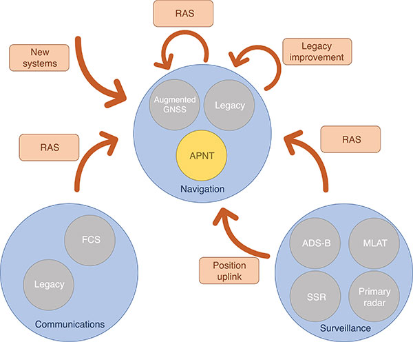
Proposed APNT solutions are generally sourced from the existing CNS environment. A common strategy is to use an aviation-certified signal not originally intended for navigation, which we have termed repurposed aviation signals (RAS). Other proposals include improving legacy systems, transmitting the ground-computed position to an aircraft, and creating new systems entirely. These sources of APNT are summarized in FIGURE 1 with explanations of the abbreviations to follow.
FIGURE 1. Sources of APNT for navigation. (Image: Weaver et al)
A natural candidate for APNT is the use of existing non-GNSS navigation infrastructure. Prior to GNSS, VOR beacons providing beacon-relative heading information and DME navaids supplying two-way range information were the primary navigation infrastructure. Improvement in DME avionics enabled tracking of multiple DME stations, providing a DME-only position solution referred to as DME/DME. Adding DME ground stations and upgrading existing hardware to increase accuracy and coverage of DME/DME positioning was therefore an attractive APNT option.
Another option sourced from the existing navigation infrastructure was to use RAS for positioning. One such RAS is that of the DME reply signal to a non-existent aircraft. By triggering DME responses in a desired fashion, aircraft can use the triggered responses for passive ranging without any change to the DME ground stations.
Communication systems for aviation are also undergoing modernization efforts. Future communication systems (FCS) are being developed to provide broadband communication capability between aircraft and controllers.
Surveillance is the domain of ground-based systems that determine the position of remote objects and is fundamental to allowing safe spacing of aircraft. Its origins reside in the development of primary radar, which was then complemented with secondary surveillance radar (SSR). Both primary radar and SSR use a rotating antenna to measure range and bearing to determine the location of the remote objects. Radar systems tend to be clustered around airports, limiting their area of coverage. To expand coverage in challenging terrain where radar is difficult to install, a technique known as multilateration is used, where a surveillance ground system can receive a signal from an aircraft and determine its position by comparing the time of arrival (TOA) of the signal between its ground stations. These systems were considered as a source of APNT by providing the aircraft position computed on the ground back to the aircraft via data uplink, but timely authentication and integrity concerns have stalled this approach in the United States.
Surveillance RAS for APNT. The other branch of surveillance-sourced APNT is by using RAS, and this is very relevant to the design of Mode N. The system providing many of the RAS for navigation is ADS-B. With this service, an aircraft broadcasts its GNSS-derived position (ADS-B Out) to ground-based stations and any aircraft capable of receiving ADS-B transmissions. ADS-B is an important part of airspace modernization strategies; it is mandated for aircraft operating in most U.S. airspace, with European mandates following suit. ADS-B ground stations, referred to as ground-based transceivers (GBT) or radio stations (ADS-B RS), collect ADS-B Out messages for use by air traffic operators. These ADS-B RS also provide their own transmissions for use by aircraft that can receive ADS-B broadcasts (ADS-B In capability) and include weather information, nearby air traffic and so on.
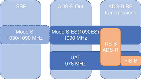
ADS-B can use different protocols to transmit its signals. The Mode S (S for selective) protocol was designed to allow SSR ground stations to selectively interrogate aircraft in their coverage area, reducing congestion on the reply frequency. The Mode S reply format consists of a four-pulse preamble and a data block containing either 56 or 112 information bits for the aircraft to provide information dependent on the interrogation received. Mode S is internationally standardized, and an extended format known as Mode S Extended Squitter was adopted for Automatic Dependent Surveillance Broadcast (ADS-B) services. Mode S Extended Squitter or 1090ES (as it’s transmitted exclusively on 1090 MHz) is also used by the ADS-B RS that rebroadcast ADS-B Out (ADS-R) and provide traffic information services (TIS-B) to nearby aircraft with ADS-B In capability.
Another protocol, used in the United States, is the Universal Access Transceiver (UAT) format. Like 1090ES, UAT is used by certain aircraft to transmit their ADS-B Out messages. Similarly, ADS-B RS transmits TIS-B and ADS-R messages with the UAT protocol; it also includes additional information that it transmits with the Flight Information Service – Broadcast (FIS-B). UAT signals are transmitted in the United States on an unused DME channel frequency of 978 MHz. FIGURE 2 summarizes the relationship between these surveillance signals and the services that use them.
FIGURE 2. Services using Mode S and UAT signal formats.(Image: Weaver et al)
Research investigating the ground-transmitted (ADS-B RS) 1090ES and UAT signals for ranging measurements greatly supports the assessment of Mode N presented here, as the Mode N system operates on a similar basis with a signal that blends characteristics of 1090ES and UAT.
Mode N Overview
Mode N (N for navigation) is a passive ranging system concept from DFS that seeks to provide APNT while reducing the spectrum congestion caused by existing aeronautical navigation and surveillance systems. The design includes the possibility for two-way and air-to-air ranging, but this overview focuses on the preferred passive mode of operation. It is designed around the Mode S format, which as mentioned, is used for SSR and ADS-B services. Despite early references to an SSR/N system, Mode N is not a new SSR mode but rather a new navigation system.
The basic concept is for Mode N ground stations to transmit on a single frequency signals that include ground station ID/coordinates, allowing aircraft with Mode N avionics to receive those signals and determine position in a similar manner to GNSS. As a single frequency is desired to minimize spectrum usage, the ground stations would space their transmissions apart to avoid intersystem interference. This scheme, known as time division multiple access (TDMA), would require information within the signal message on the scheduled time a ground station transmits, which the Mode N format allows.
Because Mode N shares many design aspects with Mode S, DME and other surveillance RAS, it is able to leverage previous APNT work for the benefit of its own analysis. Therefore, the overview of the design is described here relative to other APNT systems, as this is the basis of the preliminary performance assessment we present.
The Mode N Signal. The Mode N design proposes using the Mode S downlink signal format as the basis for its ranging signal to be used by the aircraft for passive position determination, with some key differences. The frequency channel on 1090 MHz is too congested to accommodate more signals; thus, the first difference is that Mode N intends to transmit on a different frequency. While the channel selection is still ongoing, unused DME channels have been identified as options for frequency allocation.
The second difference is the message content. As the Mode S downlink format transmits mainly aircraft-specific information, Mode N ground transmitters would instead populate their messages with information needed for passive ranging: ground station coordinates and time of transmission (TOT). The study of 1090ES messages (which also contain aircraft-specific information despite being transmitted by ground stations) as RAS required some special techniques to first identify which station was transmitting the message. The TOT is not present in 1090ES signals, but more importantly the time of transmission is not synchronized to any consistent reference. Aside from transmission frequency and message content, the Mode N signal design follows the Mode S downlink format (modulation, pulse shape and so on).
The Mode N signal also shares some aspects with the UAT signal, particularly the FIS-B segment. First, UAT is also transmitted in the United States on an unused DME channel. The FIS-B message, which provides weather information, transmits the ground station coordinates and information that can be used to estimate the TOT. Specifically, UAT messages are synced to UTC, and each ADS-B RS has a designated time slot within a one-second interval where it transmits its FIS-B message. This time slot is included in the message, and can be used to determine the TOT of the signal. Mode N is designed to work in this exact manner, minus the weather information. One crucial difference between UAT and the Mode N design is the type of modulation. Like Mode S, Mode N proposes using pulse-position-modulation (PPM) or on-off keying (OOK). The resulting wider bandwidth — estimated to be less than 4.6 MHz at –3dB — has better resistance to multipath, whereas UAT is frequency modulated to maintain a narrow bandwidth to avoid interference with DME and is more susceptible to multipath. Research on UAT signals for pseudoranging capability (also determined at a higher update rate than once per second) would be necessary for navigation, an important consideration for the final Mode N design.
Ground Infrastructure. The Mode N design, while based on RAS from the surveillance capability, requires new ground stations to transmit the Mode N signal. Requirements for the ground stations are that they provide adequate coverage to meet the requirements of an APNT system and that they are sufficiently synchronized in time. An initial time-synchronization scheme is the use of a radio frequency (RF) network consisting of the ground stations themselves, which requires radio line-of-sight of stations throughout the network. DFS performed a study and found that additional time-beacon stations would be necessary to maintain this RF time network, even though navigation coverage was provided using existing DME sites as hypothetical Mode N stations. Since these aspects of the design are still developing, the preliminary assessment we present assumes a network layout and time synchronization tolerance. As the Mode N design blends various CNS principles, a natural baseline design for the ground station locations consists of existing DME and surveillance sites in Germany. Using these locations for the ground stations enables computation of a horizontal dilution of precision (HDOP) at discrete locations throughout Germany. The assumed time synchronization is discussed further when developing a model of the Mode N ranging accuracy.
Avionics. An interesting aspect of the Mode N design is its proposed avionics unit. The Mode N avionics must be capable of receiving Mode N messages, which it can do with the existing DME antennas on aircraft. The Mode N avionics unit must then decode the messages for position determination. Its active mode for two-way and air-to-air ranging would require the Mode N avionics to transmit Mode N messages, again using the existing DME antenna.
Recognizing the continuing investment in the DME network by multiple countries, the Mode N avionics sensor is essentially built around a fully functional DME unit. This is intended to provide a seamless transition as Mode N stations are brought on line. The design of the avionics has little effect on the coverage assessment, aside from guaranteeing a minimum level of performance based on the current DME network, but is an important part of the implementation strategy. Furthermore, this blend of avionics has also been proposed for a unit compatible with DME and ADS-B (1090ES and UAT) signals.
Preliminary Coverage Assessment
Preliminary coverage assessments are a typical method to determine the feasibility of a proposed system to provide the required level of performance over a given area. A simple method of characterizing the position performance is in terms of the linear relationship between range error and DOP, where the range errors are assumed to be zero-mean, uncorrelated, and have identical distributions.
As the aircraft is assumed to have additional sensors for determining its altitude, HDOP is commonly used to characterize the expected horizontal position performance.
With range measurements, HDOP is a function of the transmitter geometry available to an aircraft at a given point. It is a straightforward computation to perform for a grid of points over the area of interest. The HDOP computation does depend on the type of range measurement, so passive (pseudo-) range, two-way range, and time difference of arrival (TDOA) measurements all have their corresponding DOP computation. Determining a model for the range error is less straightforward, and assessing the coverage potential of Mode N requires an estimation of the expected range error.
Modeling Mode N Range Accuracy. As Mode N is not an existing system, abundant quantities of real measurements are unavailable for empirically characterizing the range performance. However, since Mode N is heavily based on the Mode S signal format and functions similarly to the DME and UAT signals, which all exist and have been measured extensively, research investigating those signals can help derive the model for the Mode N range performance.
An alternate approach is to reference the standards for a specified performance level. For example, ICAO documentation specifies that the Airborne Collision Avoidance System (ACAS) logic use a zero-mean normal distribution range error model with a standard deviation of 50 feet, or about 15 meters. As ACAS also uses the Mode S signal format, this appears to be a reasonable source for the Mode N range error. However, since ACAS is an airborne two-way surveillance method, it does not exactly translate to a ground-based passive TDOA system such as Mode N. The 15-meter standard deviation is still useful, as it provides a check on the estimated Mode N accuracy. Other specifications suffer from similar drawbacks — Mode N does not directly apply to any single system. Thus, we apply the blended approach using previous APNT research.
The fundamental measurement for the passive ranging mode of Mode N is the TDOA between pairs of ground stations. This measurement is in seconds, and is translated to a range difference by using the speed of radio signal propagation in a vacuum. (See our conference paper for further details.)
Errors can be present in the TOA measurement, synchronization of the nominal TOT of the signals, and parsing of the time slot data field. The TOA measurement can have errors by inaccurate determination of the actual TOA due to noise or multipath and by the actual TOA differing from the nominal arrival time of the signal due to atmospheric delay. For terrestrial systems, propagation errors are considered to be dominated by multipath, so we don’t consider atmospheric effects here. Time synchronization errors are very important to the ranging accuracy, but it is assumed the time slot data field is parsed accurately. Other sources of error, such as inaccurate ground station coordinates, can affect the position error but have no effect on the range error. Additionally, the error originating from the change in aircraft position between reception of signals at ground stations is not considered in this article. The model of range accuracy can then be expressed as the root-sum-square (RSS) of the dominant individual error components.
We studied each error component in isolation, selecting the applicable APNT research to leverage based on the Mode N design aspect that most corresponds with that error.
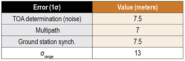
Since the Mode N design also uses a pulsed signal, the evaluation of DME (specifically, DME/N) ranging performance is the starting point for estimating the TOA noise error. Part of the APNT effort was evaluating current DME performance, as it was thought it exceeded the specified performance in standards. A study found that current DME performance allowed a budgeted TOA error of 15 meters, 2σ.
For the Mode N error model, a 7.5-meter error is an attractive option to choose as it is the average of two other sources and is the most recent. This value is a conservative estimate of the TOA accuracy for Mode N because the Mode N/S pulse shape is narrower than the DME pulse with a greater bandwidth, improving theoretical accuracy. For the preliminary coverage assessment, a conservative estimate is desired, because the actual TOA accuracy will vary over an area depending on transmitter distance — which impacts the level of signal noise. Note that the DME TOA errors are not divided by two as is done for the total DME error as they apply to a one-way TOA measurement.
After assessing the relevant studies, we modeled the multipath component of the error following that from Mode S as 7 meters, 1σ.
The final error component to estimate for Mode N is that of the synchronization of the ground stations. Based on the results from studies of the UAT signal and those from eLoran, we set a 15-meter maximum bias as a 2σ error component in the Mode N error model.
Our error analysis is summarized in TABLE 1.
TABLE 1. Predicted Mode N range accuracy. (Data: Weaver et al)
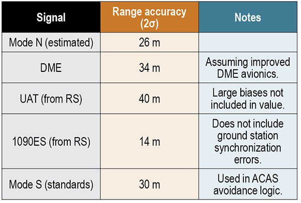
A total 2σ error for current DME performance of 92 meters has been established, which translates to 46 meters of range accuracy after dividing by two (since the DME signal is a two-way range). A substantial part of this error derives from the avionics bias, which is minimized for a “potential” DME error budget due to an assumed improved avionics performance. This results in a DME range 2σ error of 34 meters. We chose this value to compare as the effect of avionics has less of an impact in a passive ranging system such as Mode N.
Range performance for UAT signals was evaluated with measurements showing 20-meter (1σ) error when compared to GNSS truth, not including large biases attributed to ground station synchronization or processing errors. The 1090ES signals do not have an inherent ranging capability, so the TDOA measurement error of two ground station signals to one receiving station is difficult to measure. Instead, researchers have measured the differential TOA (DTOA) of one ground station signal received by two (GPS-synchronized) receiving stations to first identify which station transmitted the signal. When compared to the true DTOA based on ground station and receiving station coordinates, the measurements contained small biases around 10 meters with a standard deviation also less than 10 meters. Being DTOA measurements, these do not contain ground station synchronization errors, so the reported standard deviations correspond mostly with propagation and determining TOA. The 10-meter DTOA 1σ error can still be converted to a range error resulting in 14 meters (2σ). These results are summarized in TABLE 2.
TABLE 2. Comparison of Mode N with other APNT signals. (Data: Weaver et al)
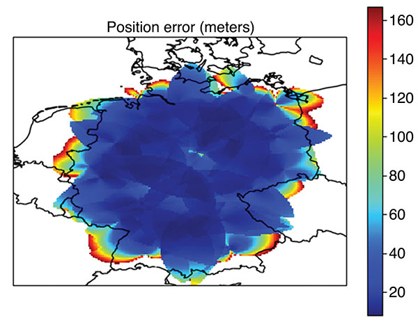
Coverage Assessment. With the estimated ranging accuracy, a preliminary coverage over Germany could now be assessed. Using the current 29 surveillance site locations in Germany and assuming that a minimum of three stations is necessary for positioning, the estimated position accuracy is shown in FIGURE 3.
FIGURE 3. Estimated position error (in meters) for aircraft within a 100 nautical mile coverage radius using existing surveillance sites as installation locations for Mode N ground stations. (Image: Weaver et al)
The coverage assessment used a “flat” Germany model with the estimated range accuracy from the preceding section (13 meters, 1σ). Atmospheric and terrain considerations were not applied in the assessment. It is important to note that this level of coverage would degrade at lower altitudes.
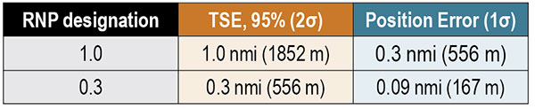
To determine whether this level of accuracy is sufficient for the airspace modernization efforts in Europe, the desired Required Navigation Performance (RNP) accuracy requirement must be examined. For RNP 1.0, where 1.0 refers to the required 95% or 2σ total system error (TSE) accuracy in nautical miles, the position error allocation is assumed to be 30% of the RNP/TSE value. The required position accuracy is shown in TABLE 3.
TABLE 3. RNP required horizontal position accuracy. (Data: Weaver et al)
From Figure 3, aircraft at altitudes within the service volume supported by a 100-nautical-mile coverage radius are capable of meeting the accuracy requirement for RNP 1.0 and 0.3 within most of Germany. Coverage along the border is unavailable as only German surveillance site locations were used.
Conclusions
Although our derivation of accuracy and the coverage assessment method we used made several simplifying assumptions, the results indicate that Mode N has the potential to be a feasible APNT system. To be a part of the modern airspace navigation infrastructure, additional accuracy requirements must also be met. The integrity requirement is harder to meet than accuracy, and requires either redundant information available to the aircraft for a receiver autonomous integrity monitoring-like algorithm or a ground-based monitoring/augmentation system. Perhaps the biggest challenge to implementing the Mode N infrastructure is maintaining an RF-based time synchronization network. Convincing aircraft operators to update their avionics is another challenge to Mode N implementation, although the inclusion of DME functionality in the Mode N avionics seeks to ease that transition.
DISCLAIMER
The views expressed herein are those of the authors and are not to be construed as official or reflecting the views of Deutsche Flugsicherung.
ACKNOWLEDGMENT
This article is based on the paper “An Overview of the Proposed Mode N System in the Context of Alternative Position, Navigation, and Timing (APNT) Development” presented at ION ITM 2021, the virtual 2021 International Technical Meeting of The Institute of Navigation, Jan. 25–28, 2021.
BRANDON WEAVER is a researcher at the German Aerospace Center (DLR) and works on alternative navigation systems.
GIANLUCA ZAMPIERI joined the Alternative Navigation Systems Group at DLR’s Institute for Communication and Navigation in 2019.
OKUARY OSECHAS leads the Alternative Navigation Systems Group in the Institute of Communications and Navigation at DLR.
By Peter Steigenberger, Steffen Thoelert, Oliver Montenbruck and Richard B. Langley
The first GPS III satellite, “Vespucci,” was launched in December 2018, started signal transmission in January 2020, and was set healthy later that month. The second GPS III satellite, nicknamed “Magellan,” was launched on Aug. 22, 2019, on a Delta IV rocket from Cape Canaveral, Florida.
Magellan, also identified by its space vehicle number (SVN) 75 (here referred to as GPS-75), started signal transmission with standard pseudorandom noise code (PRN) number 18 (here referred to as G18) on March 13. The L1 C/A, L1 P(Y), and L2 P(Y) signals were activated at 17:16:30 GPS Time (GPST), while the L1C, L2C and L5 signals followed less than two hours after Vespucci’s launch at 18:59:30 GPST. Transmission of navigation messages started at 19:00:00 GPST with GPS-75 (G18) marked as unhealthy.
PRN G18 was previously used by the 27-year-old Block IIA satellite GPS-34 that had been already removed from the active GPS constellation on Oct. 7, 2019, but continued signal transmission until March 9, 2020. GPS-75 is already being tracked by a large number of tracking stations of the International GNSS Service (IGS). Based on the data collected by these stations, the Center for Orbit Determination in Europe (CODE), headquartered in Bern, Switzerland, has been providing precise orbit and clock products for this satellite since March 14.
A comparison we performed with the CODE precise orbit products revealed initial broadcast ephemeris errors of up to 100 meters (3D) and an orbit-related signal-in-space range error (SISRE) of about 13 meters. Within four days, a SISRE (orbit component) of 24 centimeters was achieved, which closely matches the performance of the rest of the GPS constellation.
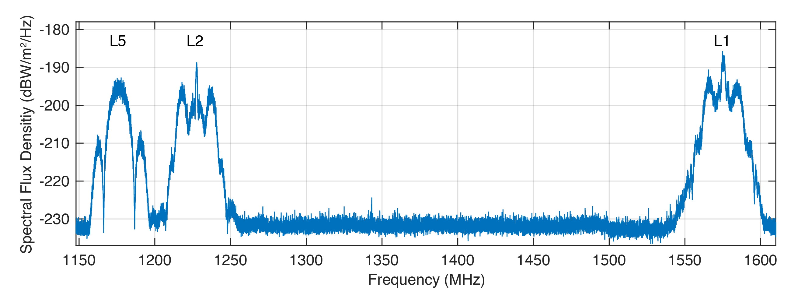
Figure 1 shows the spectral flux density of GPS-75 in the L1, L2 and L5 frequency bands obtained with the 30-meter high-gain antenna of the German Aerospace Center (DLR) located in Weilheim, Germany. The civil L1 C/A, L1C and L2C signals can be identified as sharp peaks in the center of the respective frequency bands.
FIGURE 1. Spectral flux density of GPS-75 measured with DLR’s 30-meter high-gain antenna. (Figure: Steigenberger, et al)
The prominent side lobes in the L1 and L2 bands are associated with the military M-code. The wide main lobe of the L5 signal with two smaller and sharper side lobes is caused by the superposition of two in-phase and quadrature signals with a 10-MHz binary phase-shift keying (BPSK) modulation. We found that all signals are in good shape and have a quality similar to that of the first GPS III satellite.
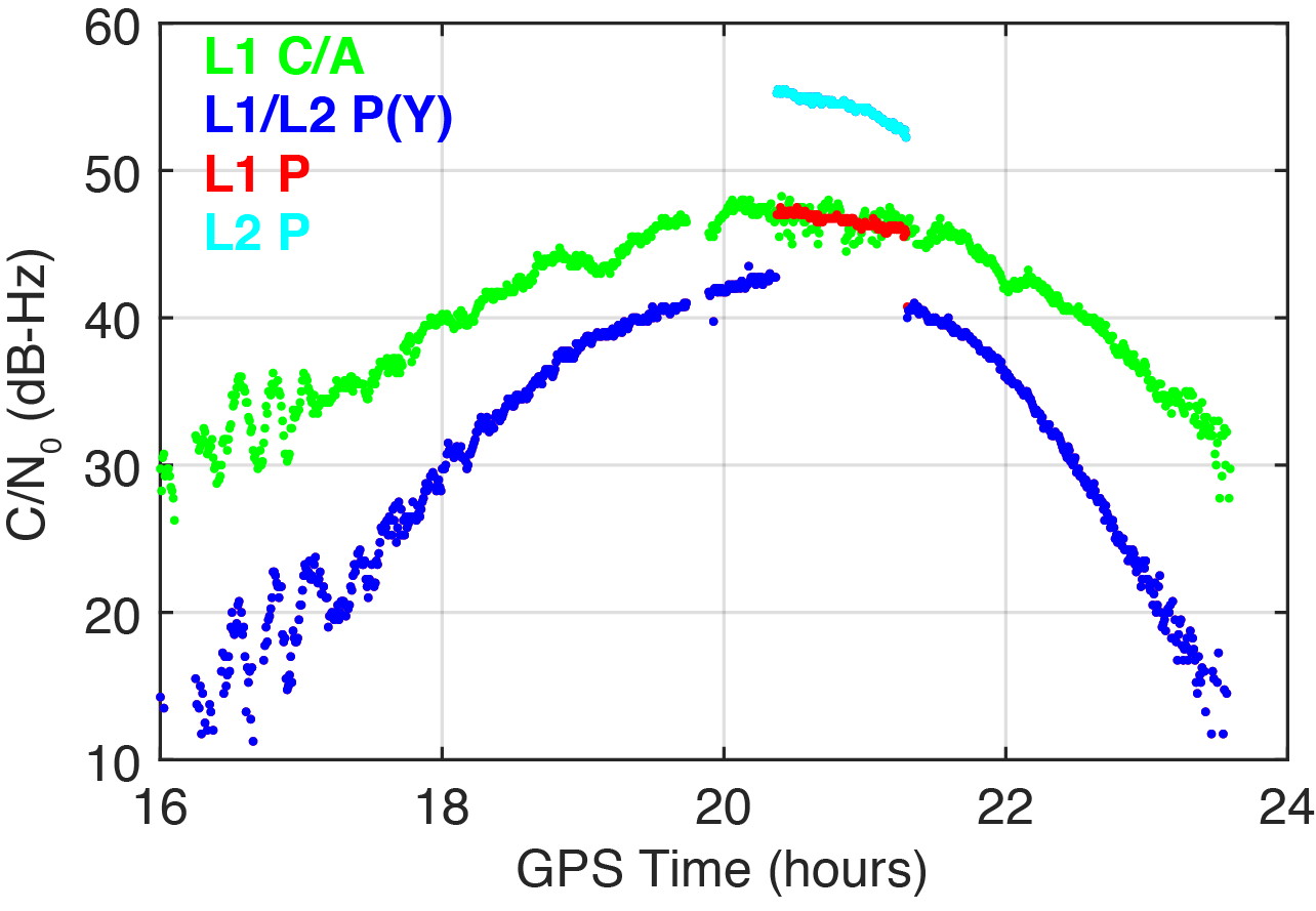
On March 16, 2020, we detected a significant change in the carrier-to-noise-density ratio of the L1 and L2 P(Y)-code signals. Figure 2 illustrates these changes for the IGS station located in Patumwan, Thailand (CUSV00THA). The L1 and L2 P-code signals are usually encrypted with the W-code to prevent spoofing (the generation of fake signals by adverse parties). The resulting encrypted signals are denoted by P(Y). Geodetic GNSS receivers are capable of tracking the P(Y) signals with a semi-codeless approach.
FIGURE 2. Carrier-to-noise-density ratio (C/N0) of the second GPS III satellite, GPS-75, tracked by the IGS station CUSV00THA in Patumwan, Thailand, on March 16, 2020. Between 20:22 and 21:18 GPST, unencrypted P-code signals were tracked. (Figure: Steigenberger, et al)
As a result, C/N0 of L1 P(Y) and L2 P(Y) are virtually identical and significantly smaller than the C/N0 of the unencrypted signals due to losses of the semi-codeless tracking technique. This can be seen in the blue-colored plot of Figure 2, where the C/N0 values of L1 P(Y) and L2 P(Y) are identical and smaller by 4.5–16 dB compared to L1 C/A depending on the elevation angle of the satellite.
However, between 20:22 and 21:18 GPST, an increase of the P-code C/N0 values was observed. The values changed by 4.5 and 12.5 dB for L1 and L2, respectively. This change is an indicator that unencrypted P-code signals were transmitted, rather than encrypted ones. This assumption can be verified by the “Anti-Spoof Flag” given as the 19th bit of the handover word (HOW) of the GPS LNAV navigation message.
Indeed, decoding of the raw navigation data from the IGS station CHOF00JPN in Chofu, Japan, showed that the Anti-Spoof Flag indicated a deactivation of anti-spoofing between 20:22:00 and 21:17:48 GPST and verified our assumption that unencrypted P-code signals were transmitted during that time period.
It has to be noted that only Javad receivers within the global multi-GNSS network of the IGS show this increase in C/N0. Other receiver types report continuous C/N0 values for the P-code signals, indicating that a semi-codeless tracking technique was continuously applied irrespective of the Anti-Spoof Flag.
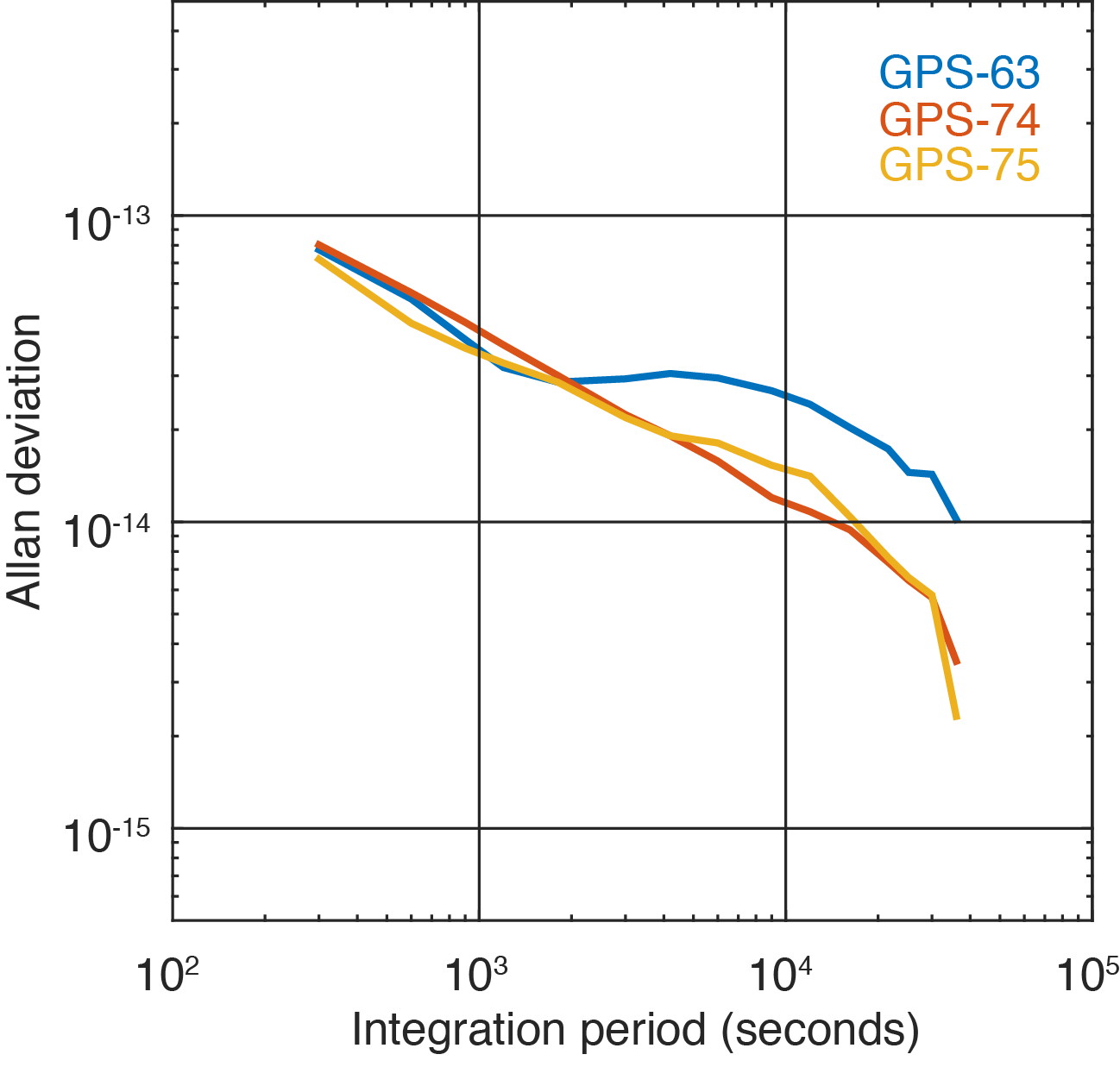
Figure 3 shows the two GPS III satellites’ Allan deviation, which measures the clock stability achieved in orbit; that is, the average frequency error over different time scales. In addition, the Block IIF satellite GPS-63 is shown, which is in the same orbital plane as GPS-75.
FIGURE 3. Allan deviation of the Block IIF satellite GPS-63 and the GPS III satellites GPS-74 and GPS-75 computed from 5-minute clock solutions produced by DLR. (Figure: Steigenberger, et al)
For integration times up to 2,000 seconds, the clock stability of GPS-75 is slightly better compared to the first GPS III satellite, GPS-74, but the situation is opposite for integration times larger than 5,000 seconds. The latter finding might be caused by the fact that GPS-75, unhealthy at the time, was tracked by a smaller number of stations compared to the healthy GPS-74.
As a consequence, the observed Allan deviation may partly be contaminated by orbit determination errors. In any case, both GPS III satellites clearly outperform the Block IIF satellite GPS-63 that suffers from thermal line bias variations visible as an increased Allan deviation starting at an integration time of about 2,000 seconds.
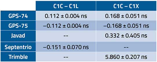
The activation of the second GPS III satellite transmitting the new civil L1C signal enables the estimation of differential code biases (DCBs) between, for example, the L1 C/A signal (Receiver Independent Exchange [RINEX] format observation code C1C) and different tracking modes of the L1C signal. Septentrio receivers track only the pilot component of the L1C signal (C1L), whereas Javad and Trimble receivers perform a combined data+pilot tracking (C1X).
DCBs are estimated from pseudorange (code) observations of a global tracking network and are corrected for ionospheric delays obtained from global ionosphere maps. The DCB estimates shown in Table 1 are based on eight days of data from 10 Javad, 21 Septentrio and 3 Trimble receivers.
TABLE 1. Differential code bias estimates in nanoseconds between L1 C/A and L1C for the GPS III satellites and average receiver DCBs. (Data: Steigenberger, et al)
As we have applied a zero-sum condition for the estimation of satellite DCBs of just two satellites, the values of GPS-74 and GPS-75 obtained from the same type of L1C observables differ only by the sign. The DCBs estimated from different L1C observables, namely C1L and C1X, differ by 56 picoseconds, corresponding to a range difference of 1.7 centimeters. The receiver DCBs are quite homogeneous for receivers from each manufacturer but differ by up to 6 nanoseconds between various manufacturers.
On April 1, 2020, GPS-75 was set healthy and joined the constellation of operational GPS satellites. The third GPS III satellite, named “Columbus,” was shipped to the Cape Canaveral launch site in February 2020. Its launch is expected no earlier than June 30, 2020, and at least two GPS III launches per year are planned for the near future.
Equipment. Measurements reported in this article were collected with JAVAD GNSS TRE_G3TH and TRE_3, Septentrio PolaRx5 and Trimble Alloy multi-GNSS, multi-frequency receivers. The spectral overview was captured with a Rohde & Schwarz EM100 digital compact receiver.
PETER STEIGENBERGER and OLIVER MONTENBRUCK are scientists at the German Space Operations Center of the German Aerospace Center (DLR). STEFFEN THOELERT is an electrical engineer at DLR’s Institute of Communications and Navigation. RICHARD B. LANGLEY is a professor at the University of New Brunswick and editor of the “Innovation” column for GPS World magazine.
Further Reading
“Optimum Semicodeless Carrier-Phase Tracking of L2” by K.T. Woo in Navigation, Vol. 47, No. 2, 2000, pp. 82-99, doi: 10.1002/j.2161-4296.2000.tb00204.x.
Interface Specification IS-GPS-200K: NAVSTAR GPS Space Segment/User Segment Interfaces by Global Positioning Systems Directorate Systems Engineering & Integration, Los Angeles Air Force Base, El Segundo, California, March 4, 2019. Available online: https://www.gps.gov/technical/icwg/IS-GPS-200K.pdf
“Apparent Clock Variations of the Block IIF-1 (SVN62) GPS Satellite“ by O. Montenbruck, U. Hugentobler, E. Dach, P. Steigenberger and A. Hauschild in GPS Solutions, Vol. 16, No.3, 2012, pp. 303-313, doi: 10.1007/s10291-011-0232-x.
“Differential Code Bias Estimation Using Multi-GNSS Observations and Global Ionosphere Maps” by O. Montenbruck, A. Hauschild and P. Steigenberger in Navigation, 2014, Vol. 61, No. 3, 2014, pp. 191-201, doi: 10.1002/navi.64
The FALCon research project has already carried out initial flight experiments with unmanned small aircraft. (Photo: German Aerospace Center)
The parachute safety solution manufacturer Drone Rescue Systems GmbH is supporting the European research project FALCon, the “Formation flight for in-Air Launcher 1st stage Capturing demonstration.”
Under the leadership of the German Aerospace Center (Deutsches Zentrum für Luft- und Raumfahrt; DLR), research is being conducted on how launch vehicles can be returned to the launch site as efficiently as possible for re-use.
The aim of FALCon is to achieve cost-efficient and environmentally friendly satellite transport. The focus of the project lies on the return of rocket stages after launch. To be able to reuse these stages, efforts are being made to recapture them in the air using a “rocket catcher.”
For the next three years (March 2019 to February 2022) the focus will be on the development and flight demonstration of a technical solution for this idea. While still in the air, rocket stages are to be captured by a transport aircraft over the sea and pulled into the vicinity of the landing site. There, the stages are to land independently.
“We are proud to be part of the FALCon research project together with five international partners and DLR as part of HORIZON2020 (EC grant 821953), the EU’s largest research and innovation program to date. The capture and towing of rocket stages in flight, that is, an autonomous and safe landing, is a particularly interesting topic for us as a manufacturer of parachute safety solutions,” said Andreas Ploier, CEO of Drone Rescue Systems GmbH.
The research project has already carried out initial flight experiments with unmanned small aircraft.
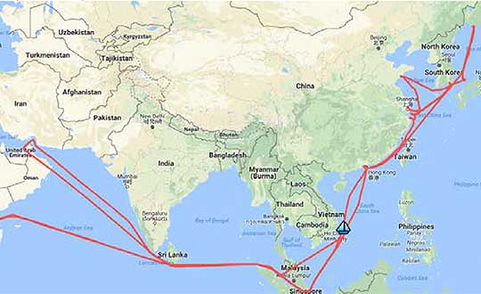
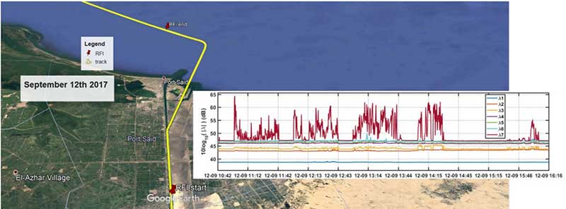
A year-long project aboard a commercial cargo ship collected tens of thousands of snapshots of radio-frequency interference in the GNSS band on a passage from Spain to Korea and back. Most interference was detected in busy port areas, less interference while transiting along coasts, and while least frequent, interference was still found in the open ocean.
Researchers at the German Aerospace Center (DLR) are still analyzing the vast amount of GNSS disruption data collected during the year-long project. Two papers have already been published about this project, and more are on the way, according to principle researcher Emilio Pérez Marcos.
In a paper presented at the Institute of Navigation last year, Marcos and his co-authors outlined the results of the last five months of this unique sampling experiment. Detection equipment was mounted on a large Hapag-Lloyd container ship. The antenna was mounted about 50 meters above the water line and provided a line-of-sight of 25km or more. The L1/E1 and L5/E5a frequency bands were continuously monitored. In addition to a “Snapshot” recording device used to save raw data samples (time snapshots), a more resilient DLR multi-antenna receiver was used to assess the impact of interferences in beamforming array GNSS receivers (semi-resilient).
As might be expected, the most interference was detected in busy port areas. Less interference was experienced while transiting along coasts. While it was the least frequent, interference was still detected during open ocean transits.
Table: Emilio Pérez Marcos and co-authors
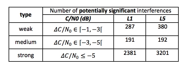
Of the 39,045 snapshots recorded, 6,632 contained radio frequency interference at 1dB or higher. Separate tests have shown that many single antenna GNSS receivers begin to perform poorly with interference signals greater than 1dB. The other 32,413 snapshots could represent interference signals that may have come from weaker transmitters, sources more distant from the ship, been the result of adjacent band transmissions, or other phenomena.
Three particularly strong and persistent interference incidents were noted in the paper.
The first was detected when the vessel was transiting the Suez Canal northbound. The interference lasted around five hours and 60km. At several points the interference prevented the DLR semi-resilient GNSS receiver from working properly, which would mean that any single antenna GNSS receiver would cease to function completely.
Vessel going north in Suez Canal. RFI detectable during approx. 60 km. Inset: Eigenvalues during the 5 hours that the RFI was detectable. (Graphic: Emilio Pérez Marcos)
The second caused the DLR receiver to fail when the vessel was entering Jebel Ali, the port of Dubai in the United Arab Emirates. The DLR receiver provided some resilience thanks to its beamforming capabilities; again any other receiver would have suffered the interference effects earlier being unable to provide any PVT. The receiver did not return to proper operation for 11 days and 5,000km. The reason for this is uncertain and under investigation.
Particularly strong interference (45dB) caused the third incident and resulted in the DLR receiver failing for three days. It began when the ship was entered the highly trafficked Malacca Straits.
The equipment used also allowed researchers to determine direction of arrival for the interfering signals and to evaluate whether the interference was a spoofing signal.
For the reported strong interference events, DLR consulted the captain of the ship, who attested and confirmed the loss of PVT in the ship’s own GNSS receiver, with all the consequences that this implies for the systems that rely on it.
The paper, “Interference and Spoofing Detection for GNSS Maritime Applications,” was presented at the ION GNSS+ conference in Miami in September of 2018. It described the last phase of a yearlong measurement effort aboard the ship by DLR. An earlier phase of the campaign has also been published in E. P. Marcos et al., “Interference awareness and characterization for GNSS maritime applications,” 2018 IEEE/ION Position, Location and Navigation Symposium (PLANS), Monterey, CA, 2018.
The authors are preparing additional papers to describe more of the results from the larger project.
In the most critical phase of the landing maneuver, the UAV flight control system must compensate for the accelerated air flow above the ground vehicle. (Photo: DLR)
Moving at 75 kilometers an hour (47 mph) an unmanned, electric, autonomous aircraft settled gently on the roof of a moving car.
Scientists from the German Aerospace Center (DLR) Institute of Robotics and Mechatronics combined robotics and unmanned aerial vehicles (UAVs) to develop a system where a fixed-wing aircraft automatically lands on a moving ground vehicle.
The DLR system is designed for commercial applications such as remote sensing and communication. It could be applied to ultra-lightweight solar aircraft that complement traditional satellite systems in the stratosphere. Or, it could support crisis management, such as aiding disaster-communications networks or providing data on climate change.
Losing weight
Ultralight solar aircraft can reach more than 20 kilometers in altitude. The weight factor is crucial to how long the ultralight can stay in the air.
The Demonstrator Platform Penguin BE UAV is equipped with redundnant landing hardware. (Photo: DLR)
By omitting the traditional landing gear, the dead weight of these UAVs can be significantly reduced. This allows more load capacity, greater range and better performance. A lighter craft also increases payload capacity, creating more space for scientific instruments.
In flight tests on an airfield in Swabia Mindelheim-Mattsies, the DLR system was successfully tested with a 3-meter, 20-kilogram, electric fixed-wing UAV. A net was provided on the roof of a car, along with optical markers. The UAV can position itself up to half a meter over the 4 x 5 meter landing platform. The optical multi-marker tracking system detects the landing apparatus and determines the relative position of the ground vehicle with high accuracy. The computer-controlled landing is then carried out.
Movement of UAV and the vehicle are adjusted with the help of special algorithms. With the car and the UAV moving at the same speed, the landing is more like a settling, making the landing safer and easier. Though designed for both autonomous car and UAV, a driver remained in the car for safety during the tests. A robotic vehicle without a driver will be tested next.
The work was supported by the EU project EC-Safe Mobile Support and complement the activities of the Flight Robotics Group.
In the semi-autonomous landing vehicle, the driver receives control commands via a graphical display. The crosshairs indicate the location of the UAV. (Photo: DLR)
Will Be Employable for Surveying, Precise Positioning, and Geodesy
By Peter Steigenberger and André Hauschild, German Aerospace Center (DLR) / German Space Operations Center
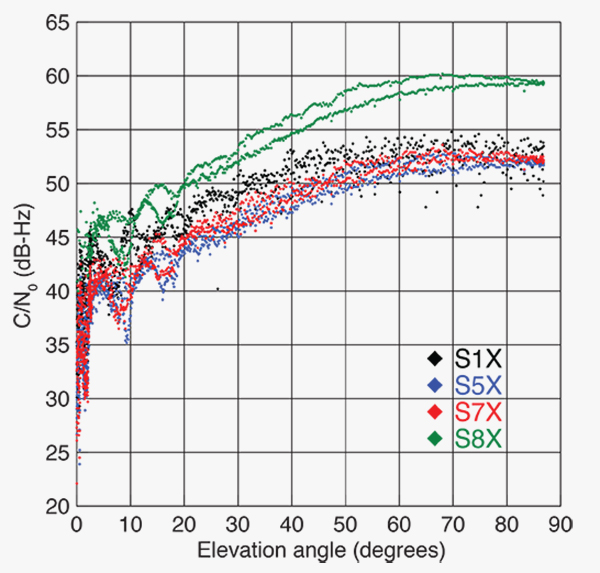
The first Full Operational Capability (FOC) Galileo satellite started transmitting L-band navigation signals on November 29, 2014. Based on data collected by a global network of GNSS tracking stations of the Cooperative Network for GNSS Observation (CONGO) and the Multi-GNSS Experiment (MGEX) of the International GNSS Service (IGS), we determined that an E1 signal with pseudorandom noise code (PRN) E18 was first tracked at the station LLAG (La Laguna, Tenerife, Canary Islands) at 06:08 UTC. A few moments later, the satellite’s transmissions were also tracked at other MGEX stations including the E5a, E5b, and E5 AltBOC signals. Based on the computed satellite visibility at various tracking stations, the satellite could be positively identified as GSAT0201, also known as Galileo FOC-FM1 or Galileo 5 with COSPAR ID 2014-050A and NORAD ID 40128.
FIGURE 1 shows the carrier-to-noise-density ratio (C/N0) of the E18 signals tracked at the CONGO/MGEX station SIN1 (Singapore, using a Trimble NetR9 receiver with a Leica AR25.3 antenna). We selected the signals from this station for analysis due to an E18 pass occurring close to the zenith and covering almost the full range of elevation angles. The E5a and E5b signals (S5X and S7X RINEX identifiers) show very similar performance, whereas the C/N0 values of the E1 signal are 1–2 dB-Hz higher. The C/N0 values of the E5 AltBOC signal (S8X) reach 60 dB-Hz at high elevation angles, which is about 6 dB-Hz higher than the other signals.
Figure 1. Galileo E18 carrier-to-noise-density ratio for the CONGO/MGEX station SIN1 (Singapore).
The first pair of Galileo FOC spacecraft was launched on August 22 with a Soyuz launcher from the Guiana Space Centre, Kourou, French Guyana. Due to a malfunction of the Fregat upper stage, the satellites were injected into elliptical orbits with an inclination of about 49° instead of near circular orbits with 55° inclination. In November, the perigee of the first FOC satellite was raised by about 3,500 kilometers by a series of 11 maneuvers with a corresponding reduction in orbit eccentricity from 0.23 to 0.16.
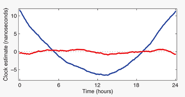
E18 has been included in the precise orbit and clock solutions of the MGEX analysis center at Technische Universität München (TUM) in Munich, Germany, since December 5. FIGURE 2 shows the detrended estimates of the active Galileo E18 clock for December 7. The presence of a pronounced quadratic term as well the large drift of 33.9 microseconds per day indicate that the active clock is a rubidium atomic frequency standard rather than a more precise passive hydrogen maser. The FOC satellites carry two of each kind of clock.
Figure 2. Galileo E18 clock estimates for December 7, 2014, with respect to the hydrogen maser at the Ottawa IGS station (NRC1) after removing an offset and drift (blue) or a second order polynomial (red).
The TUM orbit and clock product allows researchers to again compute dual-frequency positioning solutions using only Galileo observations, as the In-Orbit Validation satellite E20 has not transmitted an E5 signal since May, when a power anomaly left the satellite with the capability to only transmit an E1 signal. Furthermore, E20 currently does not transmit a navigation message.
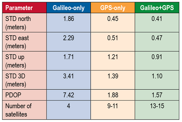
TABLE 1 shows the scatter of single-point positioning using pseudorange (code) observations from the MGEX station MAS1 (Maspalomas, Gran Canaria, Canary Islands) for a Galileo-only, a GPS-only, and a combined Galileo+GPS solution for December 6. At an elevation cut-off angle of 10°, four Galileo satellites were visible from 10:15 until 12:25 UTC (see FIGURE 3). The GPS-only solution covers the same time interval. The start time is not limited by the cut-off angle but an E18 transmission outage from 3:45–10:15 UTC.
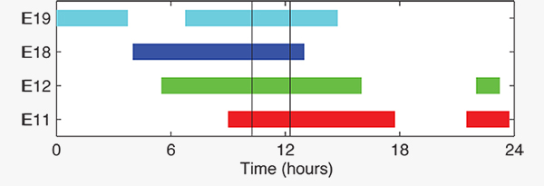
TABLE 1. Single point positioning results for the MGEX station MAS1 (Maspalomas) for December 6, 2014.Figure 3. Galileo visibility at the MGEX station MAS1 (Maspalomas) on December 6, 2014. The time period considered in the single-point positioning is indicated by vertical lines.
We used an ionosphere-free linear combination of Galileo E1 and E5 AltBOC code observations and GPS L1 and L2 code observations with a 30-second sampling interval. As the Galileo-only solution suffered from position dilution of precision (PDOP) values of up to 830, a total of 32 epochs with PDOP values greater than 25 were excluded. The geometry of the remaining epochs is still pretty unfavorable. At a mean PDOP value of 7.4, the standalone position solution exhibits a 3D standard deviation (STD) error of 3.4 meters. Use of the Galileo satellites in a combined GPS+ Galileo solution improves the positioning performance. In particular, the height component benefits from the inclusion of the four Galileo satellites with a standard deviation improvement of 25 percent.
Despite the orbit injection error, the new Galileo FOC satellite has now been successfully activated and added to the Galileo constellation. Unfortunately, the current orbit is incompatible with the standard Galileo almanac format, which may cause restrictions for some commercial receiver types.
Nevertheless, the satellite can already be tracked by a wide range of geodetic receivers with existing firmware versions and it will, in fact, be possible to use the new satellite for diverse applications in surveying, precise positioning, and geodesy, as well as in general multi-GNSS studies. We now look forward to the activation of the second FOC satellite, which can be expected in early 2015 and will, for the first time, offer multi-frequency signals from a total of five Galileo satellites.