Tag: GNSS receiver testing

  • Simulating complexity: Testing GNSS receivers requires increasingly sophisticated simulators

    Simulating complexity: Testing GNSS receivers requires increasingly sophisticated simulators

    Simulator vendors explain their evolution in response to changes in GNSS/PNT, comment on technical challenges they face, and outline principal markets.

    GNSS receivers — which were never as simple as FM radio receivers or garage door remote controls — are becoming increasingly complex. The causes for this include continuing efforts to:

    • reduce their size, weight, and power (SWAP)
    • utilize new signals from up to four GNSS constellations
    • integrate them with other sensors, such as inertial measurement units (IMUs), cameras, and lidars
    • take advantage of a growing number of public and private, global, regional, and local correction services
    • meet the requirements of booming new markets, such as autonomous vehicles
    • mitigate the threats posed by the proliferation of unintentional and intentional RF interference, the latter better known as jamming, and by spoofing.

    In short, receiver manufacturers must constantly adapt to a GNSS/PNT landscape that is, as one of the respondents to this Q&A put it, “ever evolving.”

    In turn, the growing complexity of GNSS receivers requires increasingly sophisticated simulators to test receivers and their integrations in controlled conditions before field testing and deployment. Increasingly, this is achieved by replacing with software what was once done in hardware. Simulation remains a vital, though often underappreciated, segment of our industry.

    On the following pages, five simulator vendors briefly explain their evolution in response to changes in GNSS/PNT, comment on the principal technical challenges they face, and outline their principal markets.

    Spirent Federal Systems’ GSS6450 RF record and playback GNSS simulator is portable, for testing automotive applications in the field. (Photo: Spirent Federal)
    Spirent Federal Systems’ GSS6450 RF record and playback GNSS simulator is portable, for testing automotive applications in the field. (Photo: Spirent Federal)

    Headshot: Lisa Perdue
    Lisa Perdue
    Product Line Director, Simulation
    Orolia

    OROLIA

    How has your approach to simulation changed over the years and in response to what changes in GNSS/PNT?

    We have transitioned away from the GNSS simulator approach of using fixed, allocated hardware that we used in our early simulators to the more modern software-defined approach we use today. Given the ever-evolving PNT landscape, it is difficult to design hardware that will support all future GNSS and PNT simulation needs. Instead, we focus on the development of the Skydel software platform, which can then be used with the supported COTS hardware or turnkey system to generate the necessary signals. This gives us the benefit of maximum scalability and flexibility while being truly future proof.

    The software-defined approach also allows us to offer Skydel in new and exciting ways. We aim to make PNT simulation accessible to everyone and we can do that through subscription and cloud-based simulation services.

    What are currently the greatest technical challenges to GNSS/PNT simulation?

    Today GNSS is only a part of the PNT picture. GNSS receivers are often tightly integrated with other sensors and many times the GNSS receiver cannot be isolated to test it on its own. Other sensors must also be stimulated or simulated and included as part of testing. Correction services are becoming more common, but many are proprietary with no public specification. With no common standards available, it can be technically challenging to create a one-size-fits-all test solution.

    We tackle these challenges through our plug-in feature. The plug-in architecture allows you to expand the capabilities of Skydel by adding your own features or complex integration with other systems. It allows you to exchange information with the Skydel Engine and even integrates it into the Skydel UI. With our open-source SDK, which includes example plug-ins, you can create your data outputs synchronized to the GNSS simulation, such as IMU or correction services data.

    In what markets and applications are your simulators used? Are they used only in labs or also in the field?

    At Orolia, we say ‘Skydel Everywhere.’ Skydel is used in applications ranging from military encrypted receiver testing (SAASM, M-Code, PRS) to commercial applications supporting any of the GNSS signals available.

    Skydel is used in systems that are found in labs, but you can also find Skydel at an individual engineer’s desk, or even home offices. In the field, Skydel has provided simulation and threat generation capability to authorized test ranges and field test events.
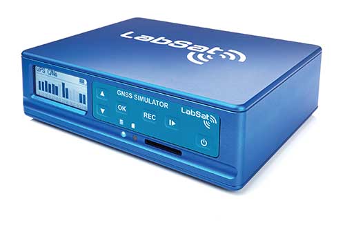
    The broadsim software-defined GNSS is powered by Orolia’s Skydel GNSS simulator engine. (Photo: Orolia)
    The broadsim software-defined GNSS is powered by Orolia’s Skydel GNSS simulator engine. (Photo: Orolia)

    RACELOGIC

    Julian Thomas
    Julian Thomas
    Managing Director
    Racelogic

    How has your approach to simulation changed over the years and in response to what changes in GNSS/PNT?

    Over the years, GNSS technology has changed significantly but our approach of identifying a need and creating a solution hasn’t changed since we launched our first LabSat GNSS simulator. We created LabSat because we needed a cost-effective, accurate and easy to use record and replay simulator that we could use for product development and production line testing for our VBOX Automotive and VBOX Motorsport technologies. This need could not be met by any other simulator manufacturer, so we developed our own solution, which in turn became LabSat. Although our approach has not changed, the needs of users, including our own engineers, have, so we continue to develop and improve LabSat to meet these needs.

    Photo: Racelogic
    Racelogic’s LabSat GNSS simulators offer multi-constellation and multi-frequency capabilities. (Photo: Racelogic)

    With the increasing number of satellite launches in market segments such as communication and navigation, the number of requests for testing space-qualified receivers has increased dramatically. To test these kinds of scenarios, we have been making some major upgrades to simulate rocket launches and Earth orbit trajectories that require very different characteristics from land-based simulation.

    As the number of constellations and signals has expanded very rapidly, the number of simultaneous signals that need to be simulated has put a far greater requirement on the computing power needed to render them. We have been working very hard on optimizing our routines to make the most of the new breed of high-performance multi-core processors. The result has been a big decrease in the time taken to create a scenario, and an increase in the number of signals that can be simulated in real-time.

    What are currently the greatest technical challenges to GNSS/PNT simulation?

    The biggest challenge is in simulating a large number of constellations and signals in real-time without using dedicated, expensive hardware to create them. The good news is that with the latest Intel Xeon processors boasting up to 40 cores and 80 threads, a much larger number of signals can now be created in real-time using off-the-shelf PC components.

    In what markets and applications are your simulators used? Are they used only in labs or also in the field?

    With the global pandemic causing national lockdowns, many engineers switched to working from home. Our largest growth in the simulator market has therefore been due to providing these engineers with a small, low cost, easy to use simulator that they can have on their desks at home, allowing them to continue to develop GNSS applications without having to go into the office. The markets these engineers work within are as varied as the markets that use GNSS technology.

    We have also seen a big increase in the use of our simulators to test mass produced satellites used in providing global internet coverage. These satellites are being produced in large volumes, and the need for a low cost, reliable testing method on the production line has driven strong growth in this area.

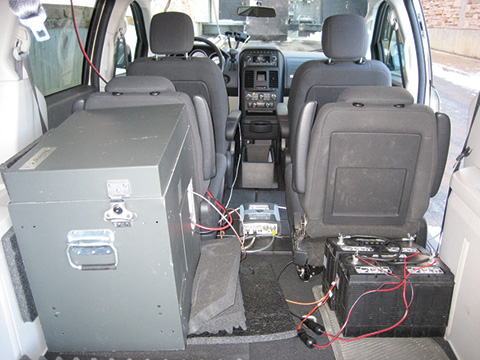
    Our simulators are often used in the field to gather data for in-lab testing, as small size and battery life are very important factors in this environment.


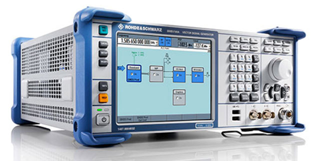
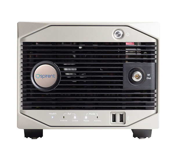
    SPIRENT FEDERAL SYSTEMS

    Photo: Spirent Federal Systems
    Phillip Bonilla
    Senior Systems Engineer

    How has your approach to simulation changed over the years and in response to what changes in GNSS/PNT?

    Spirent has provided highly accurate simulation solutions since the early phases of GPS availability, starting with defined hardware for each signal type. As the GNSS landscape has grown, Spirent has worked closely with leading developers, adding key flexibility and functionality to adapt and provide a growing product portfolio. By adopting a robustly defined system architecture, and employing signal-agnostic hardware, Spirent simulators can generate any of the available constellations and frequencies, with no more than a few clicks of a mouse.

    While broadening the support for the increasing number of constellations has been a focus, so too has the necessity to provide users with high numbers of available channels and auxiliary simulation needs. To complement GNSS simulation, significant effort is being devoted to resilient application testing, providing users with flexible solutions for introducing jamming and spoofing to the test environment. Our agnostic hardware supports signal generation using software defined radio (SDR), including interference sources and user-defined IQ signal data. As customer demands have grown, alternative RF and PNT sensors have been—and continue to be—incorporated, allowing users an expanded and comprehensive test environment.

    The new spirent simulator generates alternative RF navigation signals concurrently with GNSS signals. (Photo: Spirent Federal)
    The new spirent simulator generates alternative RF navigation signals concurrently with GNSS signals. (Photo: Spirent Federal)

    What are currently the greatest technical challenges to GNSS/PNT simulation?

    Today, nearly all industries rely on GNSS or other PNT sources to some extent. With such varied and widespread use, laboratory testing is critical, and maintaining the highest levels of accuracy, reliability and robustness remains one of the greatest challenges. For modern hardware-in-the-loop configurations, simulation systems must be able to keep latency consistent to enable powerful post-processing of results. With this challenge in mind, we at Spirent design and manufacture our own hardware, ensuring precision and ultra-low latency.

    Another significant test challenge posed by modern applications is the growth in vehicle speed and maneuverability. Creating a truly realistic test environment for supersonic and even hypersonic vehicles with high rates of spin and jerk places huge demands on a simulator. Spirent recently has introduced the industry’s first 2 kHz update rate, enabling the most accurate trajectories for the most mobile technologies.

    Lastly, positioning engines are becoming more complex. In addition to GNSS and inertial, vision systems and a range of other sensors and signals-of-opportunity are providing developers greater opportunity for precision and robustness. Therefore, a core part of Spirent’s mission statement is delivering test equipment that is designed to be integrated into wider test benches and ensuring that equipment is always orders of magnitude more accurate than any device under test.

    In what markets and applications are your simulators used? Are they used only in labs or also in the field?

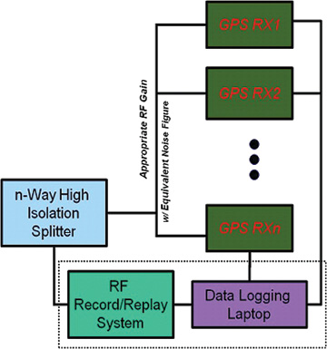
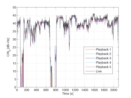
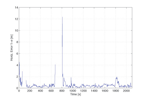
    Spirent simulators are used in all phases of the product life cycle across nearly all applications. Receiver manufacturers use our solutions beginning with initial research and development, throughout product development, and well into production and field testing. Along with the ability to use Spirent’s simulators for live range testing, Spirent’s GSS6450 record and playback system enables users to record the real world in high dynamic detail for repeatable lab testing.
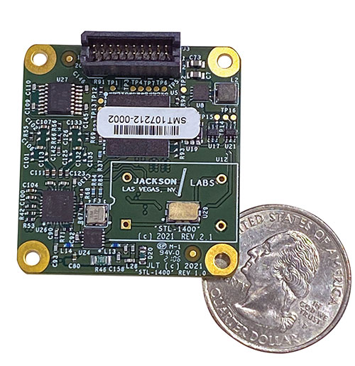

    JACKSON LABS

    Said Jackson, President and CTO. (Photo: Jackson Labs)
    Gregor Said Jackson
    President and CTO

    How has your approach to simulation changed over the years and in response to what changes in GNSS/PNT?

    Initially, we saw a large demand for GPS-only solutions. We are shipping units into this market and it is growing more than 30% year over year for us. Recently, customers are looking to also supporting other constellations. There is an emerging market for LEO simulation capability. Many LEO constellations are becoming reality, such as OneWeb, Kuiper, Starlink, Iridium, Xona, and others, and customers are more frequently asking if we can support these types of signals in our simulators. Demand also is arising for additional base-band signals to accommodate the RF signals, such as synchronized raw IMU data and other observables. Jamming and spoofing signals also are being requested and reproducing these as faithfully as possible is a big challenge for synthesized simulation. Lastly, we see demand rising for mil-type secure applications, such as M-Code, PRS (Galileo) and P(Y) code SAASM of course. The complexity of future simulators will rise in lockstep with the complexity of the RF spectrum coming to us from space.

    What are currently the greatest technical challenges to GNSS/PNT simulation?

    The STL-1400 positioning and timing receiver is designed for battery-operated low SWaP-C applications. (Photo: Jackson Labs)
    The STL-1400 positioning and timing receiver is designed for battery-operated low SWaP-C applications. (Photo: Jackson Labs)

    A faithful reproduction of the real live-sky RF signals would rank high on this list. There are almost an unlimited number of out-of-band and in-band benign and adversary RF signals on a typical GNSS antenna these days, and more recently the sun has been acting up with solar flare activity that can disrupt GNSS signals. As GNSS receivers mature and become capable of tracking four, five or more carrier frequencies and constellations at once it becomes increasingly challenging to supply these types of signals from a simulator, and at a reasonable price-point. Sometimes, a wideband recording and playback system can do a better job at reproducing live-sky signals, however these systems are limited to playing back the same exact mission over and over again of course, and thus are not very flexible.

    In what markets and applications are your simulators used? Are they used only in labs or also in the field?

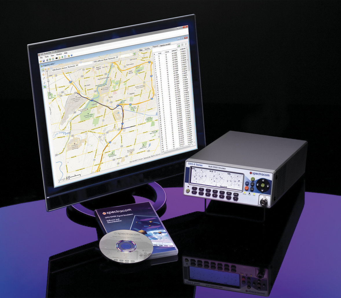
    Our simulators are built for two different applications: the first is a traditional type of GPS signal simulation where a Windows application allows a user to set up static or dynamic scenarios, allows them to upload NMEA playback files, create jamming or spoofing signals, and generally tweak the RF signal in many ways, such as modifying power levels and antenna patterns and even creating space vehicle failures in real time. Our customers range from car, aircraft, and avionics manufacturers, to R&D labs, to the government and academia.

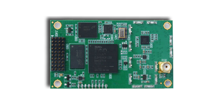
    Our simulators also are used for a hardware-in-the-loop application that we call transcoding. It allows glueless retrofitting of existing GPS equipment with any and all the emerging PNT solutions such as LEO positioning and timing, celestial navigation, INS/IMU, CSAC holdover, and concurrent/multi-frequency GNSS using a 1×1-in. transcoder module. Our transcoders fly on Air Force aircraft, are used to retrofit telecom equipment, and allow deep-indoors and underground GPS reception. Transcoders created an entirely new market for simulators.
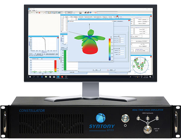

    SYNTONY GNSS

    Photo: Syntony GNSS
    Sylvain Daubas
    GNSS Simulators R&D Teams

    How has your approach to simulation changed over the years and in response to what changes in GNSS/PNT?

    Manufacturers of GNSS receivers are targeting more precision and availability, especially in urban areas, which require acquiring more signals from more constellations and greater effort to minimize multipath errors. This confirms that an SDR design for signal generation is decisive to keep systems cost-efficient, as it directly benefits from Moore’s law. For instance, our new RTGS4-12 configuration is about four times more powerful (240 channels) than our previous standard configuration, for a similar budget level.

    Regarding precision and RF quality, our simulators benefit from the same RF cards as Echo, our high-fidelity record and playback equipment, with a state-of-the-art RF front end: three channels at a 100 MHz sampling rate and a 16 bit IQ. The capacity to simulate protected signals is also crucial: with PRN Link, Constellator is ready for any present or future signal with encrypted spreading codes.

    What are currently the greatest technical challenges to GNSS/PNT simulation?

    Building a CRPA simulator is not an easy task, as this requires extreme levels of phase and time synchronization between several RF outputs, typically four, seven or more. This can be done in two ways: with a dedicated new RF board running with a single synthesizer for all channels or using the classical one, to which one should add a complex calibration mechanism. SYNTONY has made the tough choice, investing more at first in a mono-synthesizer version. However, this will benefit our customers, for which the usage will be simplified and it will save them a lot of time by shortening the calibration phase. This version already is available for sale.

    Syntony’s Constellator simulator. (Photo: Syntony)
    Syntony’s Constellator simulator. (Photo: Syntony)

    On another note, it is a significant challenge to keep our product and its interfaces user friendly while also enabling our clients to configure each of the more than 500 parameters available (at the last count). We also keep in mind that new signals may appear, from LEO constellations for instance, answering to new needs such as autonomous driving. Constellator is HW ready for them, only requiring a software update.

    In what markets and applications are your simulators used? Are they used only in labs or also in the field?

    Constellator currently is mainly used in laboratories, in many market segments. Because it was initially built in partnership with spacecraft manufacturers, it benefits from the high standards of performance of space industries and includes several advanced space-dedicated features.

    On top of the typical usage inside the labs, two other SYNTONY simulator products that are directly derived from Constellator are used in the field:

    • ECHO Recorder & Playback is used to record the GNSS environment with ultra-high fidelity: today @ 100Mhz, and before the end of 2021 even up to @ 200Mhz. ECHO has been used by our customers in cars, trains and often in aircraft test flights. Another usage of ECHO is to detect and record scintillation phenomena, as we will soon do in Brazil.
    • SubWAVE (GNSS coverage extension for underground places) allows indoor positioning with precision, directly compatible with standard GPS receivers, which can be crucial for safety or operational reasons. We have installed SubWAVE inside subways stations and tunnels (for example, in Stockholm, Paris and New York), in road tunnels (soon in France, in the “Tunnel du Mont Blanc”), in an underground bus terminal (also in Stockholm), in underground train stations (in Switzerland), and before the end of 2021 also in an underground mine (in Finland).
  • IZT Solutions’ over-the-air system tests GNSS receiver performance

    German research organization Fraunhofer Gesellschaft has developed and presented an over-the-air (OTA) wave-field synthesis system for test and certification of GNSS receivers. The testing platform is at its Fraunhofer IIS Facility for Over the Air Research and Testing (FORTE) in Ilmenau, Germany.

    The innovative and complex OTA test system is based on hardware and software solutions from IZT GmbH, such as powerful RF receivers and high-performance signal generators.

    The demonstrated setup to test GNSS receivers represents a new approach that — in contrast to conventional conducted and open-field tests — realistically emulates real-world scenarios under controllable and repeatable conditions, enabling the realistic comparison of receivers and algorithms. The OTA test system is cost-effective, flexible and scalable.

    The newest generations of mobile communication systems employ multiple antennas for transmission and reception, such as LTE, LTE-A, WIMAX and Wireless LAN. Multiple Input Multiple Output (MIMO) OTA test systems are typically deployed for certification, performance testing and product evaluation of broadband wireless devices. The related devices have to be tested in their related environments.

    In contrast to mobile phones, GNSS receivers are extremely susceptible to all types of interference. Hence, the goal was to develop a new testing method for interference robustness of GNSS receivers.

    The OTA Test Approach

    The OTA test laboratory comprises a satellite signal emulator (Spirent) used as signal source, several OTA channel emulators used for wave-field synthesis that are able to emulate any electromagnetic environment in an anechoic chamber, and several OTA illumination antennas. The OTA channel emulators from IZT GmbH support 8 input and 32 phase coherent output channels (up to 256 logical channels) in the frequency range of 1 to 6 GHz, and provide the output signals to the OTA illumination antennas. Note that the final extension of the system based on the IZT components will have 12 x 32 channels.

    The unique test environment developed at FORTE together with IZT GmbH excels in its great flexibility regarding possible applications in communications technology. The new OTA emulation approach enables realistic radio channel emulation taking into consideration multipath propagation, multi-frequency, and multi-user scenarios.

    The OTA system supports emulation of complex channel impulse responses of nearly unlimited length. Besides GNSS equipment, the test system can be applied for LTE and Cognitive Radio (CR), sensor networks (including energy networks and smart metering) or car-to-car and car-to-infrastructure communications.

    The Innovationszentrum für Telekommunikationstechnik GmbH IZT is a spin-off of the Fraunhofer-Gesellschaft, Germany’s leading institution for applied research. Founded in 1997 in Erlangen, the company emanated from the Fraunhofer Institute for Integrated Circuits (IIS). It specializes in advanced digital signal processing and field programmable gate array (FPGA) designs in combination with high-frequency and microwave technology.

  • Spirent to Demo GSS9790 Simulator in ION GNSS+ Session

    Spirent Federal Systems will demonstrate its GSS9790 simulator at ION GNSS+, taking place Sept. 14-17 in Tampa, Fla.

    The Spirent demonstration “Interference and Anti-jam Antenna Testing Using the Spirent Wavefront Simulator (GSS9790)” will take place in Room 17 on Thursday, Sept. 17, 2-2:45 p.m. Attendance gains one ticket for an Apple Watch raffle, with the winner to be announced Thursday at 4 p.m., Booth C in the Exhibit Hall.

    The ability of a CRPA to null out unwanted signals while still allowing wanted signals to be received is key to its performance. This ability allows GNSS receivers to continue to operate in challenging signal environments, Spirent said in an email. The similar but slightly different signal composition at each antenna element allows the CRPA to distinguish direction for wanted and unwanted signals. Recreating this signal environment in an anechoic chamber is critical in allowing the discerning test professional to rigorously evaluate the performance of a CRPA system.

    The Spirent GSS9790 is designed for this testing. The 9790 allows for code, carrier and amplitude control on a satellite-by-satellite and interferer-by-interferer basis.


  • Rohde & Schwarz Offers Fast Production Testing for GNSS Receivers

    Rohde & Schwarz Offers Fast Production Testing for GNSS Receivers

    Rohde & Schwarz designed its GNSS simulator for the R&S SMBV100A with a focus on production testing of GNSS receivers.
    Rohde & Schwarz designed its GNSS simulator for the R&S SMBV100A with a focus on production testing of GNSS receivers.

    Rohde & Schwarz now offers a new, speed-optimized production tester — the R&S SMBV100A vector signal generator equipped with the R&S SMBV-P101 package.

    During production testing of modules and receivers for satellite-based communications, the basic GNSS signal reception and the connection between the antenna and GNSS chipset need to be checked. The GNSS production tester simulates separate satellites for the GPS, GLONASS, BeiDou and Galileo navigation standards in the L1/E1 band specifically for these production tests.

    The four satellite constellations can be activated individually, each with a high dynamic range of 34 dB. Level changes can be made on the fly without interrupting the signal, enabling users to simultaneously perform independent sensitivity tests for each navigation system. The 1 pps or 10 pps GNSS marker allows exact time synchronization between the tester and the DUT. Pure, level-stable CW signals can also be generated to calibrate the test setup or to simulate interferers.

    The R&S SMBV-P101 option additionally offers test functions for efficient characterization of GNSS chipsets, Rohde & Schwarz said. As a result, a receiver’s ability to handle high-movement dynamics can be verified quickly and cost-effectively. To do this, users can access both predefined and user-defined Doppler profiles, from which the R&S SMBV100A automatically generates the appropriate satellite signal.

    The R&S SMBV-P101 GNSS production tester package for the R&S SMBV100A is now available from Rohde & Schwarz.

  • Successful Testing — and Why It Is More Important Than Ever

    By John Pottle and Neal Fedora

    John Pottle
    John Pottle

    Precision matters. While “accuracy” is somewhat one-dimensional, “precision” is multi-faceted. We submit to you that whatever area of GNSS-based location you are interested in, precision matters today and will matter more in the future. In this column, we’ll explain why this is.

    Traditional test approaches involve taking measurements to evaluate fundamental performance, for example, time-to-first-fix. As the number of critical applications that rely on positioning, navigation and timing (PNT) increases, the list of considerations for testing also grows.

    Critical applications typically require higher integrity. There are a myriad of techniques to achieve this, from adding constellations, additional frequencies, improved navigation message authentication approaches and everything in between. Examples of safety-related applications include rail, connected car and aviation. Commercially critical application examples are smartphone payment authentication and container port automation. Protecting the warfighter and ensuring mission success against growing interference and jamming are key initiatives for the military. All of these applications are becoming more sophisticated and complex, stressing the importance of precision in testing.

    Neal Fedora
    Neal Fedora

    Testing these critical applications requires:

    • Precise and clear test objectives
    • Precise definition of test approaches to explore both nominal and off-nominal conditions
    • Comprehensive test tools that include all required signal components precisely modeled and controlled
    • Test signal precision of at least an order of magnitude better than the device under test
    • Results analysis that can quickly and effectively highlight areas of interest or concern.

    Robustness against Cyber Attacks. The second area calling for more precision is the need for a more robust PNT systems in the face of increasing cyber attacks and interference. While well known in the IT world, the GNSS community is relatively unfamiliar with being targeted by hackers. Attacks on GNSS technologies are increasing in frequency and sophistication for both commercial and military users. The stakes are rising as the incidents increase from occasional (often accidental) interference to more structured and organized approaches to jamming and even spoofing.

    We’re predicting a game of cat and mouse where these cyber attacks and interference threats will continually evolve to try and stay one step ahead of the protections in place. In our view, this will call for increasingly clever and proactive threat-detection techniques in navigation systems, in addition to precise, reliable test solutions to verify them.

    Spirent’s test solutions address these growing demands by providing not only multi-GNSS signal simulators, but also inertial and interference simulators, anti-jamming test solutions, and record and replay of actual observed interference and even communications port vulnerability testing.

    In our view, the diversity of critical applications will increase, emphasizing the need for a precise approach to test planning, execution and analysis. Robust PNT is an achievable vision, and we are excited for the future.


    John Pottle is marketing director for Spirent Communications plc. Neal Fedora is director of engineering for Spirent Federal Systems Inc.

  • Spectracom Begins Program for Application-Specific Testing

    Spectracom Begins Program for Application-Specific Testing

    Spectracom’s GSG-6 Simulator with monitor.
    Spectracom’s GSG-6 Simulator with monitor.

    Spectracom has begun a program to develop robust application-specific testing solutions. The program fills what the company calls a technology and expertise gap in providing customers in a variety of industries the tools to perform more comprehensive qualification of their mission-critical systems. Examples of these industries include:

    • multi-constellation (GPS, GLONASS, Galileo, BeiDou) simulation;
    • integrated MEMs/INS testing;
    • interference detection and mitigation (IDM) verification;
    • assisted-GNSS (A-GPS) validation,
    • hardware-in-the-loop (HIL) testing for automotive applications;
    • high-dynamic platform simulations for aerospace and defense (UAVs, UASs); and
    • precision agriculture/surveying testing via RTK/differential measurements.

    “Our full featured platform of multi-GNSS simulation capabilities  combine flexible hardware and user oriented software to deliver  the functionality and user interfaces necessary for today’s demanding test scenarios,” said Spectracom CTO, John Fischer. “We understand, however, that even the most powerful tools often need something more to reduce complexity, increase productivity and ensure consistent, reliable results. Toward these ends we are excited to bring our extensive applications knowledge directly to our customers to design and deliver custom configurations and test systems that are unique to their applications.”

    Today’s PNT applications combine data from a variety of receivers, sensors and other sources. Spectracom is designing its solutions to integrate simulated GNSS RF with all other data sources in the test system for true “hardware-in-the-loop” verification, the company said.

    For instance, Spectracom’s new assisted-GNSS (A-GNSS) feature is designed to integrate with 3GPP/LTE testers to send “assistance data” directly to the device under test. The company takes a similar approach to testing RTK-enabled receivers with user-settable virtual base-station parameters.

    “Spectracom’s value is to partner with our customers to ensure they have the ability to easily use GNSS simulation as part of a comprehensive PNT testing solution,” said Rohit Braggs, Director of Marketing and Strategy. “More testing in the lab enables faster time to market, at a reduced cost and increased reliability. We are asking developers of the most demanding PNT applications to put us to the test.”

  • Nexteq Navigation Offers Platform for Accelerating GNSS Receiver Development

    Nexteq Navigation Offers Platform for Accelerating GNSS Receiver Development

    Nexteq Navigation has launched accelGRx, a platform for accelerating professional-grade GNSS receiver development. The platform provides open and production-ready hardware and software building blocks for GNSS receivers. accelGRx is designed for organizations looking to research and develop new techniques and algorithms requiring deep in-receiver integreation or quickly produce a small, high-performance receiver.

    accelGRx supports GPS L1 and Beidou B1, and the hardware is GLONASS and Galileo ready. It pairs a compact form factor and industry standard pin layout with a code and phase precision of 4 cm and 0.4 mm respectively for both GPS L1 and Beidou B1. It incorporates an array of software development tools, including the ability to record and play back digitized signals.

    An accelGRx licensee wil have tools to develop and test new deep in-receiver integration techniques and algorithms:

    • Access to all source code, logic and tools
    • Deep in-receiver access to real-time GNSS information
    • PC-based software model of receiver platform
    • Store and playback of digitized signals for development and testing
    • Testing with production-ready receiver and real-world conditions

    An accelGRx licensee will have the necessary assets and tools to begin commercialization immediately after development is complete:

    • Hardware design (schematic, PCB layout, and BOM)
    • FPGA logic design
    • Full tracking and PVT source code
    • Receiver operating system
    • Design documentation and manuals

    Nexteq also released two other products:

    matrixRTK is a combination of the PPP and network RTK approaches to benefit network-RTK vendors. matrixRTK has the benefits of network RTK (fast initialization) with the benefit of PPP (no baseline restrictions).

    L1-RTK-systems is a solution that allows our handheld users to use 2/L1 high sensitive GNSS handhelds working as base and rover to achieve 2-20 cm level accuracy. This is a reliable and cost-effective solution for field workers, Nexteq said.

  • Spirent Announces Test System for Hybrid Sensor Fusion for Indoor Positioning

    Spirent Communications has launched its SimSENSOR MEMS (Micro-Electro-Mechanical Systems) sensor simulation software. SimSENSOR is targeted at the R&D environment and enables performance testing of sensor fusion algorithms in navigation systems that include MEMS inertial sensors and multi-GNSS.

    SimSENSOR works in tandem with Spirent’s multi-GNSS constellation simulators by simulating MEMS sensor outputs on a common trajectory with the simulated GNSS signals. Trajectories that include representative human motion gestures, such as arm movements, are included with SimSENSOR. The ability to test fusion algorithms that take inputs from a wide variety of sensors is supported, including accelerometers, gyroscope, magnetometer, digital compass, and barometric height sensors. Representative MEMS noise models and errors such as bias and drift are also included and are available under user control.

    “SimSENSOR is designed for customers who want to optimize sensor fusion architectures,” said Rahul Gupta, product manager with Spirent’s Positioning Technology business. “Sensor fusion is increasingly being used to enable a wide range of applications including indoor positioning. SimSENSOR is a unique tool for accelerated, lab-based R&D in support of this ground-breaking work. It will also help to extend Spirent’s leadership in testing hybrid positioning technologies in mobile devices.”

    In 2007 Spirent launched SimINERTIAL to test inertial navigation systems involving high-grade GPS/inertial units suitable for military applications. SimSENSOR benefits from the experience gained by Spirent, in particular in relation to ensuring coherency and stability between GNSS and simulated sensor output streams.

    SimSENSOR is now available for order.

  • GNSS Receiver Evaluation

    Record-and-Playback Test Methods

    This article addresses how best to quantify “which navigation system performs best” in a realistic testing scenario. The methodology focuses on land vehicles navigating in urban environments, but applies equally well to pedestrian navigation and can be adapted for testing assisted-GNSS implementations. During a drive test, the truth-reference system and RF recording system log samples to disk, with no need for the receivers under test to be included during the actual drive. 

    By Eric Vinande, Brian Weinstein, Tianxing Chu, and Dennis Akos, University of Colorado, Boulder

    FIGURE 1. Traditional in-vehicle receiver testing.
    FIGURE 1. Traditional in-vehicle receiver testing.

    Radio frequency record-and-playback systems (RPS) have recently become commercially available. These systems sample the RF environment and store it to disk during a drive test and can replay it through receivers back in the lab environment. Here we explore the improvements in dynamic testing methodology created by these units.

    RPS test system installation.
    RPS test system installation.

    RPS constitute a stark contrast to more traditional signal simulators that use pre-defined trajectories and mathematical models to determine appropriate RF output. Signal simulators attempt to reproduce environmental error factors such as multipath, inertial aiding system errors, and building and vehicle obstructions. They rely on mathematical models to simulate these various error sources. In some cases they do a reasonable job of reproducing these errors, but the dynamic urban environment is so complex (for example, rapidly varying/fading signal strength(s), multiple multipath signals, short/long duration obstructions of multiple layers) that even a sophisticated mathematical model can not replicate all effects completely. Some simulators include software that enables the user to define a trajectory and a limited amount of urban scenario details. Again, only so much realism can be created in a simulation environment. Existing testing standards are simulator-based, and as such, are circumscribed by the signal simulator limitations in representing a dynamic environment.

    Positioning performance of a satellite navigation receiver under test (RUT) is coupled with its RF front-end system and local oscillator quality. Because of the variation in RF components between RUTs, some likely have superior RF interference (RFI) immunity. RFI can be a serious issue in certain land vehicles due to on-board electrical systems or because of external interference sources.

    This article describes a testing method applicable to all receiver types, and complementary to that described in the December 2009 GPS World article by Mitelman and colleagues, “Testing Software Receivers,” regarding validation testing within a production environment. Added elements include taking into account truth-system uncertainty and a repeatability verification of the RF playback process through non-deterministic hardware receivers.

    We present here the dynamic testing approach currently used at the University of Colorado in Boulder for receiver evaluation and comparison in the urban environment. The approach also includes the ability to assess the effect of sensor augmentations (for example, inertial, environmental) on positioning performance.

    Truth Reference. Comparison with a truth reference system is essential for evaluation of satellite navigation receivers. For dynamic testing, this typically includes a survey-grade receiver coupled with a tactical-grade (or better) inertial measurement unit (IMU) and associated carrier-phase differential post-processing software. This software is filter-based and provides a positioning-error estimate in various components. Truth reference systems provide a continuous position estimate whose quality can vary depending on factors experienced in the urban environment, including length of full/partial satellite signal outage. In this study, we subtracted the 99th-percentile horizontal positioning error estimate of the truth system from the nominal RUT positioning error at each reporting epoch, as shown in Figure 2.

    If the RUT position happens to lie within the truth-system position uncertainty, it is not considered to have any position error.

    We focus here on a method to evaluate and compare mass-market, consumer-grade receivers to survey-grade receivers. One difference between these two receiver types is the way they handle the trade-off between accuracy and availability. Consumer receivers strive to provide the user with the highest availability, whereas survey receivers’ goal is to maximize accuracy. As a result, consumer-grade receivers will produce more regular position updates in harsh signal-tracking conditions, but must sacrifice accuracy to do so.

    FIGURE 2. RUT position error calculation
    FIGURE 2. RUT position error calculation

    Current Testing Standards

    Currently accepted A-GPS standards such as those used by the 3rd Generation Partnership Project (3GPP) provide very limited dynamic testing in simulated urban conditions, being mainly designed to evaluate the first position calculation achieved in a particular simulated scenario. High-sensitivity receivers that pass or greatly exceed the 3GPP tests, in our opinion, are not guaranteed to have superior navigation performance in urban areas. Also, local oscillator performance is not specified. The trajectory dynamics imposed can actually be much smaller than the clock dynamics of a very low-cost local oscillator. A GPS receiver cannot tell the difference between the two and must track the effective Doppler variation.

    The 3GPP defines five independent tests for A-GPS receiver certification. They include tests in the areas of: sensitivity with coarse/fine time assistance, nominal accuracy, dynamic range, multipath performance, and moving scenario/periodic update performance. The last three tests include elements that ostensibly pertain to the urban environment. These tests specify discrete, constant signal power levels for implementation in a hardware signal simulator. The discrepancy between the 3GPP-prescribed signal levels and those observed during actual drive testing is detailed as follows.

    The 3GPP moving scenario/periodic update performance test trajectory is shown in Figure 3.

    FIGURE 3. 3GPP dynamic testing trajectory (van Diggelen, A-GPS: Assisted GPS, GNSS, and SBAS, Artech House)
    FIGURE 3. 3GPP dynamic testing
    trajectory (van Diggelen, A-GPS: Assisted
    GPS, GNSS, and SBAS, Artech House)

    This test profile calls for the simulation of five satellites with a constant signal strength of 2130 dBm while the vehicle travels around the racetrack trajectory. In contrast, during an actual drive test in an urban area, a receiver reported the distribution of carrier-to-noise-density values for all tracked satellites as shown in Figure 4. This more accurately shows the range of signal strengths that should be expected in urban conditions.

    FIGURE 4. Drive-test C/N0 distribution
    FIGURE 4. Drive-test C/N0 distribution

    The 3GPP moving test is considered passed if positions are reported regularly, and 95 percent of them are within 100 meters of the true position. This is not a particularly difficult test for a RUT to retain signal lock through, as the linear acceleration is about 0.15 g and the centripetal acceleration is about 0.25 g.

    It is difficult for independent third parties to carry out a receiver evaluation following 3GPP guidelines as several of the tests require receiver restarts, which in turn requires testing automation. Depending on the receiver-evaluation hardware availability, restart commands may not be available to to an independent evaluator.

    3GPP receiver testing results are quoted as pass or fail over a large number of short evaluations. For the dynamic environment, the system performance over continuous time is required to make a proper comparison between evaluated receivers.

    In general, evaluating the GPS engines embedded within cell phones or other devices is difficult. Most are not made to interface with an external antenna, and the mere act of adding an antenna connection can significantly alter performance. The output format is not always documented, if it is even available to an end user. To allow fair across-the-board comparisons, GPS chipset manufacturers should make available development kits that have external antenna connections and well-documented message output formats.

    Drive-Test Configuration

    Current live dynamic testing requires multiple systems to be operating in a moving vehicle (see opening Figure 1). A truth-reference system, usually a high-grade GPS/INS device along with post-processing, provides the basis to which all other RUT are compared. This system requires a dedicated vehicle rooftop antenna with the best possible sky view, separate from a lower-grade test antenna located within the vehicle. Each RUT is connected to the representative consumer-grade antenna located in the vehicle through a high-isolation splitter that suppresses inter-receiver interference. It is important at this point that the gain be set appropriately for each RUT, depending on the front-end expectations while maintaining an equivalent noise figure across all receivers.

    Visualization Methods

    In addition to quantitative methods, we have created a qualitative visualization to assist with interpretation of the raw data. The same parsed data sets that provide the statistical script input are fed into a viewer script along with the post-processed truth reference data. With the truth-reference system data plotted in the center of the screen, each RUT is then plotted the correct distance and direction away, based on the distance and direction of error compared to truth. The receiver plots are overlaid onto Google Earth images centered on the truth-reference location. Plots of number of satellites utilized (top right of Figure 5) and elevation (middle right) as reported by each receiver and the sampled RF spectrum (lower right) are also included.

    For each reporting epoch, based on the data frequency of the truth-reference system, a frame is generated with the aforementioned characteristics. These frames are gathered and encoded into a movie clip which can then be used as a quick and simple qualitative tool for receiver comparison. Figure 5 shows an individual movie frame. A forward-looking camera capability is also being added to this movie so the test environment can be documented from multiple angles.

    FIGURE 5. Movie visualization screenshot
    FIGURE 5. Movie visualization screenshot

    While observing this movie, variations in the sampled RF spectrum from interference or blockages can be associated with the current landscape. Locations of RFI sources can be identified and avoided (or included) in future testing. These RFI and significant blockage locations are of interest for receiver RF component and navigation filter development. The next three figures show spectrum snapshots during various parts of a drive test. In Figure 6, the cumulative GPS spectra rises above the noise floor and is visible during open sky conditions. While below ground level, Figure 7 shows only the front-end filter shape (and relatively minor RFI). Figure 8 shows an example of severe RFI when near a specific parking garage location.

    FIGURE 6. Open-sky spectrum (centered on 1575.42 MHz)
    FIGURE 6. Open-sky spectrum (centered
    on 1575.42 MHz)
    FIGURE 7. Spectrum while below ground level (centered on 1575.42 MHz).
    FIGURE 7. Spectrum while below ground
    level (centered on 1575.42 MHz).

    FIGURE 8. Spectrum near interference source (centered on 1575.42 MHz).
    FIGURE 8. Spectrum near interference
    source (centered on 1575.42 MHz).

    Record/Playback Concept

    To overcome the limitations of hardware signal simulators and repeated vehicle drive testing, the RF record/playback testing method is utilized at the university. Commercially available equipment, capable of recording and playing back an RF signal, has recently become available. Equipment options exist for between $10,000–100,000, with 1–16 bit sampling and 4–25 MHz front-end bandwidth.

    Figures 9 and 10 show the concept of “record once, playback many times.” During a drive test, the truth-reference system and RF recording system log samples to disk. There is no need for the RUT to be included during the actual drive test.

    FIGURE 9. Recording mode block diagram.
    FIGURE 9. Recording mode block diagram.
    FIGURE 10. Playback mode block diagram
    FIGURE 10. Playback
    mode block diagram

    In the laboratory, the logged RF samples are replayed through a splitter to all RUT. The effect of receiver configuration changes can be evaluated without having to repeat the drive test. At a later time, additional receivers can also be tested using the same stored RF sample file.

    During separate record and playback phases, testing considerations and methods discussed previously are implemented.

    Since the recording process can only obviously capture current conditions, additional drive-test collections are required if different satellite geometry is desired, or if additional representative antennas need to be evaluated.

    Repeatability of RPS Testing

    To validate that the playback signal levels were not significantly different from live signals, we conducted an urban, dynamic evaluation. Figure 11 shows that there is typically not more than a 1 dB difference in reported C/N0 between live and playback modes when testing a receiver that only reported integer values. The two dropout instances were excursions into parking garages.

    FIGURE 11. Live and playback C/N0 values
    FIGURE 11. Live and playback C/N0 values

    Figure 12 compares the navigation statistics between replays, using the same five playbacks as in Figure 11. The playbacks show a 1-sigma horizontal position solution spread under 1 meter for approximately 83 percent of the test.

    FIGURE 12. Playback Horizontal Position Error Spread.
    FIGURE 12. Playback Horizontal Position Error Spread.

    These two figures verify the repeatability of the RPS testing method and solidify it as an alternative to both signal-simulator testing and live testing of satellite navigation receivers.

    Denver Testing Method

    To evaluate the RPS concept, we conducted tests in three locations: Boulder, Denver, and Interstate Highway 70, all in Colorado. The Boulder and Denver locations were urban collections, while the Interstate 70 location was a natural canyon with significant elevation change. The collection at each location was repeated with two different representative antennas (patch and cell phone) at nearly the same sidereal time in order to keep the overhead satellite constellation similar.

    We examine here the November 11 and 16 Denver tests. The November 11 test used a patch antenna that places nearly all its gain in the upward direction, making it more immune to interfering sources below and to its sides. Figure 13 shows the patch antenn
    a location on the van, as well as the truth-system antenna location utilized for testing on both days.

    FIGURE 13. Patch antenna (dashboard) and truth-system antenna (rooftop) locations.
    FIGURE 13. Patch antenna (dashboard) and
    truth-system antenna (rooftop) locations.

    The November 16 test used a cell-phone GPS antenna that does not have a preferential gain direction, making it more susceptible to interfering sources below and to its sides. This antenna type is representative of the typical low-cost antenna (in some cases as simple as a piece of wire) found in consumer cell phones. Figure 14 shows the cell-phone antenna suction-cup mounted to the front window of the testing van. The representative antenna mounting location was chosen to minimize locally-generated RFI effects while also being representative of a typical vehicle-use case.

    FIGURE 14. Cell-phone antenna location.
    FIGURE 14. Cell-phone antenna location.

    The required equipment and connections are minimal when performing RPS drive testing, as no RUTs are included. The inset to Figure 1 at the beginning of this article shows the RPS unit in the rear of the van, mounted on layers of foam to reduce vibration, which, if not properly addressed, can cause errors in mechanical hard drives writing data at high rates. Also visible are the truth receiver on the center of the van floor, and the car batteries for powering it and the IMU. The IMU is mounted to the vehicle frame and is not shown.

    The test drive trajectory through Denver on November 11 and 16 as reported by the truth system is shown in black in Figure 15 and is also repeated in Figures 16 and 17. The test lasted approximately 40 minutes on both days. It started in the upper left part of Figure 15 and continued zig-zagging through downtown to the lower right.

    FIGURE 15. Truth trajectory for November 11 and 16 tests.
    FIGURE 15. Truth trajectory for November 11 and 16 tests.

    Figures 16 and 17 show particularly difficult blocks for the four receivers tested under the replay method. These receivers are denoted A (green), B (blue), C (red), and D (yellow).

    FIGURE 16. Difficult block #1 during November 11 test and truth system antenna (rooftop) locations.
    FIGURE 16. Difficult block #1 during November 11 test and truth
    system antenna (rooftop) locations.

    The horizontal positioning error statistics for two receivers on the November 11 test are shown in Figures 18 and 19. The left side shows horizontal error in two different zoom levels. The right side shows a histogram and cumulative distribution of errors, and several reporting metrics over the entire test. Even though receiver A in general outperformed receiver B, from the error time histories there are noticeable periods where both receivers simultaneously had positioning difficulties.

    FIGURE 17. Difficult block #2 during November 11 test.
    FIGURE 17. Difficult block #2 during November 11 test.

    Table 1 summarizes the horizontal positioning statistics for all receivers during both tests. Positioning accuracy was severely degraded when replaying samples collected with the cell-phone antenna as compared to the patch antenna. Receiver A was the most accurate across both tests, while receiver B was the least accurate. The uncertainty of the truth system was subtracted out when producing the horizontal positioning results for all receivers.

    Table 1
    Table 1

    Conclusions

    The record-and-playback system testing approach, in our opinion, represents the best way to test hardware receivers. It overcomes the fidelity limits of simulator-based testing, especially when considering the difficult-to-model urban environment. During receiver development, it requires only a single drive test for each location, as sampled RF data can be replayed from disk.

    FIGURE 18. Receiver A horizontal positioning error statistics (November 11 test).
    FIGURE 18. Receiver A horizontal positioning error statistics (November 11 test).
    FIGURE 19. Receiver B horizontal positioning error statistics (November 11 test).
    FIGURE 19. Receiver B horizontal positioning error statistics (November 11 test).

    Having demonstrated that RPS testing is repeatable, we have produced a library of RF sample files representing real-world conditions for continued receiver development and testing purposes.

    • Eric Vinande is Ph.D. student at the University of Colorado studying GPS/MEMS inertial sensor integration and urban RFI aspects.
    • Brian Weinstein is a BSEE student participating in the Undergraduate Research Opportunity Program for GNSS receiver testing at the University of Colorado.
    • Tianxing Chu is a visiting researcher at the University of Colorado from Peking University where he is a Ph.D. student.
    • Dennis Akos is an associate professor within the Aerospace Engineering Sciences Department at the University of Colorado with concurrent appointments at Stanford University and Luleå University of Technology.

    Manufacturers

    Development of the methodology described here used two different RPS systems, one from LabSat (RaceLogic) and one from Averna. The test data come from the Averna system.