Tag: GPS data

  • The differences between published Geoid18 and Geoid12B values in Southern Louisiana

    The differences between published Geoid18 and Geoid12B values in Southern Louisiana

    My February 2020 column provided an analysis of the differences between the latest published hybrid Geoid18 values provided on NGS’ Datasheet and the computed geoid height value using the published NAD 83 (2011) ellipsoid height and NAVD 88 orthometric height. The column highlighted issues on differences due to published heights that have changed since the database pull for Geoid18. It mentioned that future columns will address differences in other portions of CONUS. This column will focus on differences between published Geoid18 values and Geoid12B values in Southern Louisiana. Why are users seeing large differences between the two models?

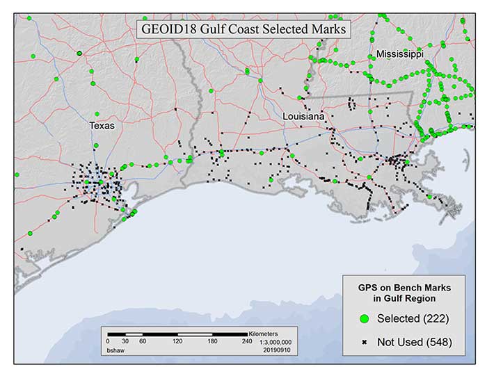
    My last column mentioned that the technical report on Geoid18 provided a good explanation on the stations used in the United States Gulf Coast region. See box titled “GPS on Bench Marks for GEOID18 in the Gulf Coast Region.”

    GPS on Bench Marks for GEOID18 in the Gulf Coast Region

    (https://www.ngs.noaa.gov/GEOID/GEOID18/geoid18_tech_details.shtml)

    There are areas of complex vertical crustal motion in the Texas/Louisiana Gulf Coast region of the United States which render many control station elevations in the region invalid. The selection of GPS on Bench Marks in this region was limited to the small number of marks where the leveling and GPS data agreed to minimize the influence of crustal motion in the hybrid geoid model. Figure 1 depicts the selection of stations used in the hybrid geoid model along the Texas/Louisiana Gulf Coast. (Image: National Geodetic Survey)
    Figure 1: GEOID18 Gulf Coast selected marks: There are areas of complex vertical crustal motion in the Texas/Louisiana Gulf Coast region of the United States which render many control station elevations in the region invalid. The selection of GPS on Bench Marks in this region was limited to the small number of marks where the leveling and GPS data agreed to minimize the influence of crustal motion in the hybrid geoid model. Figure 1 depicts the selection of stations used in the hybrid geoid model along the Texas/Louisiana Gulf Coast. (Image: National Geodetic Survey)

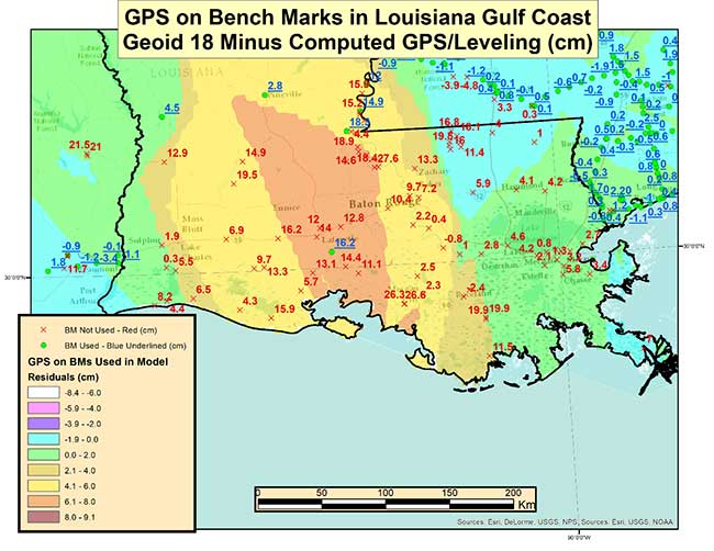
    As highlighted in the last column, very few stations in Southern Louisiana were used in the creation of the Geoid18 hybrid geoid model. As provided in my last column the box titled “Differences on GPS on Bench Marks in the Gulf Coast Region” depicts the differences between the published Geoid18 value and the computed geoid value using the latest NAD 83 (2011) ellipsoid and NAVD 88 orthometric height.

    Differences on GPS on Bench Marks in the Gulf Coast Region

    Image: National Geodetic Survey
    Image: National Geodetic Survey

    The plot indicates that there are many large differences. Many of these differences are to be expected because the Southern Louisiana is an area of known crustal movement. NGS recognizes this and includes the statement below on datasheets for stations published in Southern Louisiana (see box titled “Statement on NGS Datasheet for Stations in Southern Louisiana”).

    Statement on NGS Datasheet for Stations in Southern Louisiana

    This station is in an area of known vertical motion. Due to the variability of land subsidence, uplift, and crustal motion, NGS has, determined the orthometric heights for marks in these suspect subsidence areas should be considered valid only at the epoch date associated with the orthometric height. These heights must always be validated when used as control. All previously superseded orthometric heights are now considered suspect and are available in the superseded section. NGS does not recommend using suspect or superseded heights as control.

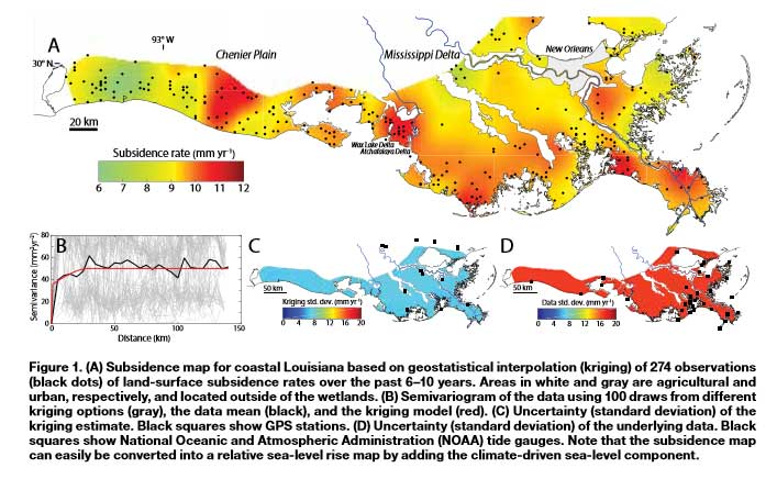
    As stated above, Southern Louisiana is an area of crustal movement. There have been many reports that have described the crustal movement in this region. A few examples include “Vulnerability of Louisiana’s coastal wetlands to present-day rates of relative sea-level rise,” “A New Subsidence Map for Coastal Louisiana,” “Spatio-temporal Modeling of Louisiana Land Subsidence Using High-resolution Geo-spatial Data,” “Anthropogenic and geologic influences on subsidence in the vicinity of New Orleans, Louisiana” and “Rates of Vertical Displacement at Bench Marks in the Lower Mississippi Valley and the Northern Gulf Coast.” The figure in the box title “Figure 1 from A New Subsidence Map for Coastal Louisiana,” from a 2017 report, provides an estimate of the subsidence in coastal Louisiana.

    Looking at the figure indicates that there is a significant variation of subsidence occurring in coastal Louisiana. The legend indicates that the subsidence rates range between 0.6 to 1.2 cm/year.

    Figure 1 from A New Subsidence Map for Coastal Louisiana

    (https://www.geosociety.org/gsatoday/groundwork/G337GW/GSATG337GW.pdf)

    Image: National Geodetic Survey
    Image: National Geodetic Survey

    The box titled “Excerpt from Anthropogenic and Geologic Influences on Subsidence in the Vicinity of New Orleans, Louisiana” depicts estimates of crustal movement between 2009 and 2012 in the vicinity of New Orleans. Several of the areas in the plot indicate subsidence rates exceeding -1 cm/year. Once again, the figure shows the local variability of subsidence rates.

    Excerpt from Anthropogenic and Geologic Influences on Subsidence in the Vicinity of New Orleans, Louisiana

    Check out page 5 of this PDF.

    Last year, NGS performed the Multi-Year CORS Solution 2 (MYCS2). This was described in previous columns, which can be viewed here and here. The MYCS2 process generated computed and modeled velocities for CORSs. The box titled “CORS NAD83 (2011) Vu Velocities” is a plot that depicts the velocities in the “upward” component in cm/year for NOAA CORS that are operational and have a computed velocity in Southern Louisiana. So, what does this mean to estimating a hybrid geoid model in Southern Louisiana?

    CORS NAD83 (2011) Vu Velocities

    Image: National Geodetic Survey
    Image: National Geodetic Survey

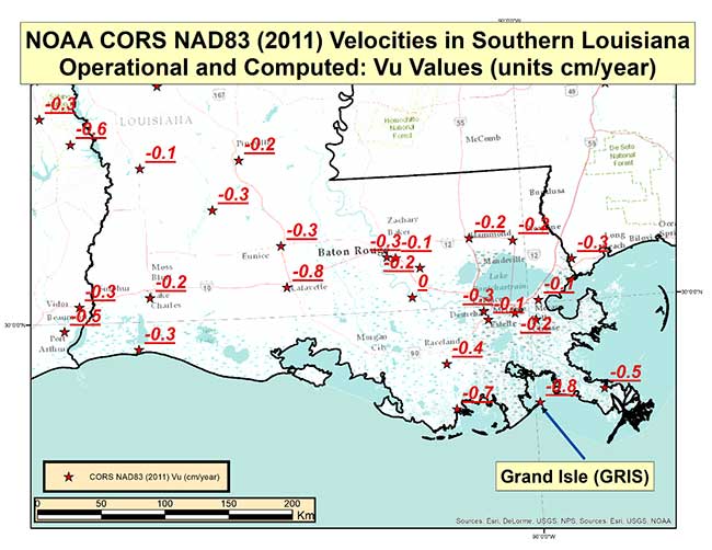
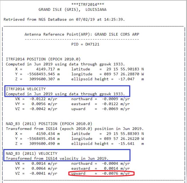
    The plot indicates that the rates vary from -0.1 cm to -0.8 cm. It should be noted that these stations are CORS and they are typically installed on structures that may not capture the entire amount of subsidence at the land surface. The box titled “CORS Position and Velocity for Station GRIS” provides an example of a CORS sheet from NGS CORS website.

    CORS Position and Velocity for Station GRIS

    (https://www.ngs.noaa.gov/cgi-cors/CorsSidebarSelect.prl?site=gris&option=Coordinates14)

    Data: National Geodetic Survey
    Data: National Geodetic Survey

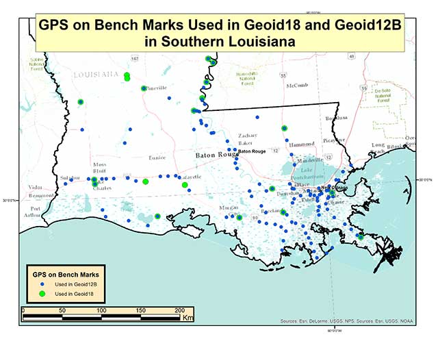
    Now, let’s look at differences between Geoid12B and Geoid18 in Southern Louisiana. The box titled “GPS on Bench Marks Used in Geoid18 and Geoid12B” depicts the stations used in Geoid12 and those used in Geoid 18. As indicated in the plots, there were a lot more stations used in the generation of the Geoid12B model than those used to create the Geoid18 model.

    GPS on Bench Marks Used in Geoid18 and Geoid12B

    Photo: National Geodetic Survey
    Photo: National Geodetic Survey

    The box titled “Differences between Geoid12B and Geoid18 in Southern Louisiana” provides the values of Geoid12B minus Geoid18 in centimeters on the GPS in Bench Mark stations used in Geoid12B.

    Differences between Geoid12B and Geoid18 in Southern Louisiana

    Photo: National Geodetic Survey
    Photo: National Geodetic Survey

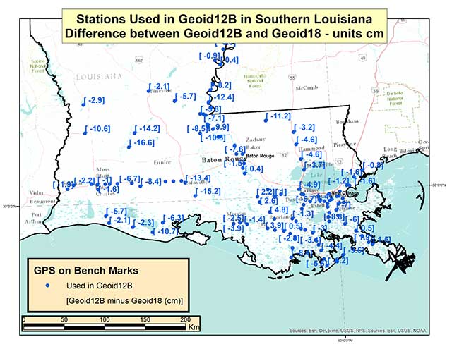
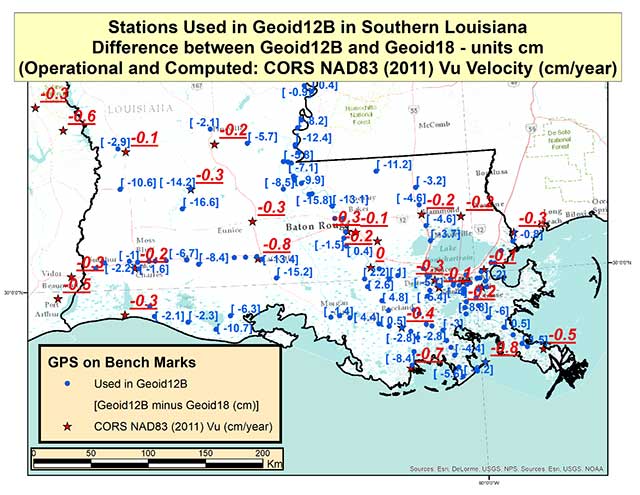
    As indicated in the plot, there are some large differences between Geoid12B and Geoid18 values; a few differences exceed 15 centimeters. Based on the previous discussion of crustal movement in Southern Louisiana, this probably shouldn’t come as a surprise. The box titled “Differences between Geoid12B and Geoid18 with Vu Velocity Values” depicts the differences in the hybrid geoid models and the NAD83 (2011) CORS Vu rate.

    Differences between Geoid12B and Geoid18 with Vu Velocity Values

    Photo: National Geodetic Survey
    Photo: National Geodetic Survey

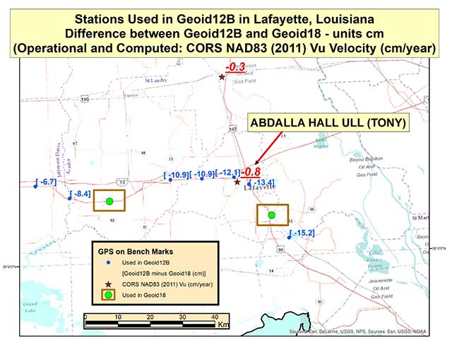
    The box titled “Differences between Geoid12B and Geoid18 in Lafayette, Louisiana” depicts the differences in the two hybrid geoid models and the NAD83 (2011) CORS Vu rate values in the Lafayette, Louisiana, region. This region has some of the largest differences between Geoid12B and Geoid18 values in Southern Louisiana. As indicated in the plot, CORS station TONY has a Vu rate of -0.8 cm/year which is fairly large, and the differences between Geoid12B and Geoid18 values are fairly large at the -10 to -15 cm level. Once again, users should expect differences between the two hybrid geoid models because there has been movement in the area and because different GPS on Bench Mark stations were used in the generation of the hybrid geoid models. In the Lafayette region the two stations used in the generation of Geoid18 were not used in Geoid12B (see stations highlighted in a box).

    Differences between Geoid12B and Geoid18 in Lafayette, Louisiana

    Photo: National Geodetic Survey
    Photo: National Geodetic Survey

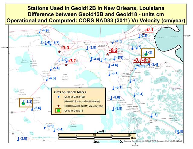
    The box titled “Differences between Geoid12B and Geoid18 in New Orleans, Louisiana” depicts the differences in the hybrid geoid models and the NAD83 (2011) CORS Vu rate values in the New Orleans, Louisiana, region. Two of the same stations that were used in the development of Geoid12B and Geoid18 are highlighted with a box. The difference between the two geoid model values are much less in this region compared with the Lafayette region. The CORS Vu velocities are also less than the CORS station (TONY) value in Lafayette. Saying that, the differences on stations not used in Geoid18 have differences ranging from -4 to -8 cm going southward toward the Gulf of Mexico. Once again, Southern Louisiana is subsiding so these differences are not surprising.

    Differences between Geoid12B and Geoid18 in New Orleans, Louisiana

    Photo: National Geodetic Survey
    Photo: National Geodetic Survey

    This means if someone uses NGS’ OPUS web tool to compute a GNSS-derived orthometric height, the NAVD 88 GNSS-derived orthometric height could be significantly different than the published stations in this region. Some of the difference could be due to the difference between the Geoid12B and Geoid18 published values, and some could be due to crustal movement in Southern Louisiana. Saying that, I mentioned in my last column that NGS performed a large GNSS network project in Southern Louisiana in 2016. The GNSS-derived ellipsoid heights were loaded in NGS’ database in March 2019, but the GNSS-derived orthometric height from the 2016 project are not yet finalized so they have not been loaded into NGS’ database. Once finalized and loaded into the database, the 2016 GNSS-derived orthometric heights should be more consistent with GNSS-derived orthometric heights estimated using the NGS’ OPUS web tool. This column focused on differences between published Geoid18 values and Geoid12B values in Southern Louisiana. It provided reasons why users may see large differences between the two models.

  • Tesla granted US patent for positioning tech

    Tesla granted US patent for positioning tech

    Tesla has developed a technology aimed at providing more accurate positioning for autonomous cars by sharing data between vehicles, according to a U.S. patent application.

    The patent, “Technologies for vehicle positioning,” was filed in 2017 and made public in December 2018.

    Solutions include cameras detecting matching locations and using other vehicles in its fleet as “cooperative reference stations” to share raw GNSS data and make positioning corrections.

    Tesla describes in the patent, “The inventions increase such positioning accuracy via determining and applying offsets (corrections) in various ways, or via sharing of raw positioning data between a plurality of devices, where at least one knows its location sufficiently accurately, for use in differential algorithms.”

    Techniques include:

    • a reference station sharing a positional offset with an automobile,
    • a reference station calculating and sharing a set of parameters (offsets and corrections) for various error components including atmospheric, orbital and clock,
    • a reference station sharing its raw GNSS data so that vehicles can remove errors through differencing or other calculations.

    Tesla also would correct GPS data by matching camera data with vision maps to detect the exact location of a vehicle. With this vision-map matching localization approach, “a location estimate is varied until the location estimate makes a camera-reported lane boundary coincide with a map-reported lane boundaries,” the patent reads.

    Schematic of Tesla’s system shows two vehicles (102, 120) feeding data to a network, a server and a reference station. (Image: Tesla)
    Schematic of Tesla’s system shows two vehicles (102, 120) feeding data to a network, a server and a reference station. (Image: Tesla)
  • Moving mountains: Alps researchers detect a decade of movement

    GPS data serves as the basis for a geodetic model of the Alps. Here, a horizontal strain field is derived from the data. Red areas indicate compression; blue indicates lateral spreading. (Image: DGFI-TUM)
    GPS data serves as the basis for a geodetic model of the Alps. Here, a horizontal strain field is derived from the data. Red areas indicate compression; blue indicates lateral spreading. (Image: DGFI-TUM)

    Our Earth is constantly on the move, as the current Kilauea eruption dramatically illustrates. But capturing data on small shifts over time isn’t so easy.

    A new computer model based on more than a decade of GPS data shows the dynamic movements of the Alps as the mountain range drifts and rises.

    In general, the range drifts an average of one-half millimeter and rises 1.8 millimeters every year.

    However, there are strong regional variances. In South and East Tyrol, a rotation towards the east is superimposed on the overall movement, while at the same time the mountain range is being compressed. And the rise in height is not identical everywhere, either. While very small in the southern part of the western Alps, it reaches its maximum with a speed of more than 2 millimeters per year in the central Alps at the boundaries of Austria, Switzerland and Italy.

    To create the model, researchers at the Technical University of Munich (TUM) German Geodetic Research Institute evaluated measurements made by more than 300 GPS antennas over a period of 12 years, in the German, Austrian, Slovenian, Italian, French and Swiss Alps. Over that time, each of the stations has been making positioning measurements every 15 seconds.

    The team’s model makes the movements visible on a comprehensive basis for the first time.

    The scientists identified the positions of the measurement stations, accurate down to fractions of a millimeter; many of the stations were set up in the EU project ALPS-GPSQUAKENET and are in part operated by TUM.

    Once corrected for snow weight and atmospheric interference, the data show horizontal and vertical shifts as well as lateral spreading and compression at a resolution of 25 kilometers.

    Explains Florian Seitz, chair of Geodetic Geodynamics, “The data are a goldmine for geodesy, with its objective of accurately measuring the surface of the Earth and identifying any changes occurring.”

    Visit https://doi.org/10.5194/essd-2018-19.

  • GPS Data, Satellite Images Used to Study Icelandic Caldera

    MSimons-BardarbungaVolcano-caldera
    This Landsat 8 image, Caltech acquired on Sept. 6, 2014, is a false-color view of the Holuhraun lava field north of Vatnajökull glacier in Iceland. The Bárðarbunga caldera is visible in the lower left of the image under the ice cap.
    Photo: U.S. Geological Survey / Caltech

    Access to satellite images and GPS data has allowed scientists to document the collapse of the Bárðarbunga caldera, a volcano beneath the Vatnajökull ice cap in Reykjavik, Iceland.

    Mark Simons, a professor of geophysics at the California Institute of Technology (Caltech), traveled to Reykjavik with 15 students and two faculty members on Aug. 16, 2014, to lead a tour of the volcanic, tectonic, and glaciological highlights of Iceland. That day, earthquakes occurred  — the seismicity was related to the Bárðarbunga caldera.

    Simons is one of the leaders of a Caltech and Jet Propulsion Laboratory (JPL) project known as the Advanced Rapid Imaging and Analysis (ARIA) program, which aims to use a growing constellation of international imaging radar satellites that will improve situational awareness and response following natural disasters, according to Caltech. Under the ARIA umbrella, Caltech and JPOL, managed for NASA by Caltech, had formed a collaboration with the Italian Space Agency (ASI) to use its COSMO-SkyMed (CSK) constellation — consisting of four orbiting X-Band radar satellites — following such events.

    CSK used an interferometric synthetic aperture radar (InSAR) technique to gather images of the surface of the glacier above the caldera. By the evening of Aug. 28, Caltech says the first interferogram showed that the ice above the caldera was subsiding at a rate of 19.685 inches a day.

    Simons took the data to researchers at the University of Iceland who were tracking Bárðarbunga’s activity on Aug. 29.

    “At that point, there had been no recognition that the caldera was collapsing. Naturally, they were focused on the dyke and all the earthquakes to the north,” Simons said. “Our goal was just to let them know about the activity at the caldera because we were really worried about the possibility of triggering a subglacial melt event that would generate a catastrophic flood.”

    The flood never occurred, but Caltech says the researchers at the University of Iceland increased their observations of the caldera with radar altimetry flights and installed a continuous GPS station on the ice overlying the center of the caldera.

    The Icelandic researchers published a paper in December 2014 in Nature about the Bárðarbunga event, largely focusing on the dyke and eruption. Simons and his colleagues have developed a model to describe the collapsing caldera and the earthquakes produced by that action. The new findings appear in the Geophysical Journal International.

    Bryan Riel, a graduate student in Simons’s group and lead author on the paper, used the interferogram of the Bárðarbunga area, along with four others collected by CSK in September and October, to show that the earthquakes were not the primary cause of the surface deformation inferred from the satellite radar data.

    “What we know for sure is that the magma chamber was deflating as the magma was feeding the dyke going northward,” Riel said in the article. “We have come up with two different models to explain what was actually generating the earthquakes.”

    “Because we had access to these satellite images as well as GPS data, we have been able to produce two potential interpretations for the collapse of a caldera — a rare event that occurs maybe once every 50 to 100 years,” Simons said. “To be able to see this documented as it’s happening is truly phenomenal.”