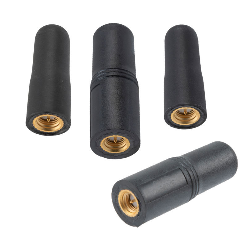
Pasternack has released a series of GNSS antennas that meet military specifications for use in several small form factor and mobile applications.
The mil-spec GNSS antennas are engineered for environmental performance according to the MIL-STD-810G standard and include multi-standard GPS L1, Galileo E1 and GLONASS options.
The MIL-STD-810G GNSS antennas are IP67 rated. They are available in passive and active versions and provide coverage from 1,597 MHz to 1,607 MHz. The GNSS antennas feature linear polarization for cross-polarized isolation, nominal gain options of -3 dBic and 10 dBic, and SMA mounts.
Focus Telecom has introduced a new timing product for defense and mission-critical applications, the Time-Loader.
The Time-Loader can be deployed in environments where GNSS signals are denied or disrupted, to support any ground, naval and airborne system that needs real time of day (TOD) and 1PPS external synchronization aligned to UTC or GNSS.
In this emerging era of rapid tactical deployment of defense systems, communications intelligence, missile defense systems, radar/electro-optical sensors and UAS batteries in the field are often in GNSS-denied or jammed environments. This situation creates challenges for access to real time and accurate time of day.
To solve this problem, the Time-Loader generates a GPS L1 C/A code RF output as if the signal were coming from a live-sky GPS antenna. It provides full-constellation GPS output and is compatible with external GNSS receivers. It encodes times with nanosecond accuracy for GPS timing receivers.
The Time-Loader’s GPS-disciplined oscillator (GPSDO) is the Microsemi MAC-SA53/55, which provides excellent UTC accuracy with outstanding hold-over rubidium clock performance.
The Time-Loader is the size of a suitcase, hand-carried and easily deployed. It activates quickly from a cold start or when sensors are deployed for the first time.
Included in the Time-Loader is a self-contained, miniature GPS simulator that provides real-time extremely accurate signals. The 18-channel full-constellation simulator stores location/time/date data in internal memory and stores complex vector data to simulate dynamic scenarios. The simulator also can be used to transcode NMEA or SCPI position/velocity/time (PVT) data into GPS RF signals.
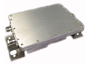
The GAJT-410MS provides anti-jamming to marine vessels. (Image: NovAtel)
Hexagon | NovAtel has released the GAJT-410MS in response to the increase of interference and jamming in marine environments worldwide. The GAJT-410MS is the company’s latest addition to its proven GPS Anti-Jam Technology (GAJT) for the commercial and defense marine markets.
The low size, weight and power (SWaP) variant protects civil and military operations from interference and jamming, with jammer direction-finding capabilities for enhanced situational awareness in the marine environment.
The GAJT-410MS provides dynamic protection on both GPS L1 and L2 bands, as well as Galileo E1, QZSS L1 and L2 and SBAS L1 to combat intentional and unintentional interference. If a vessel experiences jamming, the device’s direction-finding capabilities provide improved situation awareness of their RF environment to identify and locate the source of the jamming signals.
The commercial off-the-shelf, non-ITAR solution is easy to install or retrofit onto existing fleets, enabling assured PNT for continuous operations, cybersecurity and safe navigation at sea, NovAtel said.
Interference, both benign and malicious, is a challenge facing civilian and military operations. Commercial marine applications like shipping, tankers and bulk carriers are under threat from interference targeting their navigation and cybersecurity. Without assured positioning, these vessels can drift off-course and place the vessel, crew and cargo at risk.
Nearshore marine applications like survey, construction and piloting also require reliable positioning for uninterrupted operations in crowded waterways and RF environments. Interference mitigation and jammer direction-finding for advanced situation awareness ensure users acquire assured positioning, navigating and timing (PNT) while identifying and limiting risk from interference sources.
“Assured navigation and cybersecurity defenses are growing priorities for marine users as global threats from interference and jamming increase,” said David Russell, marine segment portfolio manager for Hexagon’s Autonomy & Positioning division. “The GAJT-410MS is an anti-jam solution protecting vessels from interference and jamming disruptions to ensure continuous operations wherever your application takes you. With GAJT, your position, navigation and timing are protected and assured.”
The GAJT-410MS is the latest iteration of proven, high-performance anti-jam products from NovAtel. It includes flexible mounting options, jammer presence and direction-finding capabilities for advanced situation awareness.
Every ounce counts on a drone. While a larger ground plane on a GNSS patch antenna improves its performance, the additional size increases weight — an unacceptable tradeoff.
The antenna’s location on the drone is another factor. It must be distant from motors and other electronic components that generate interference, which undermines positional accuracy. But remote locations are often off-limits because the antenna’s weight in those spots would disrupt the delicate balance drones require.
Drone-maker Parrot took these factors into consideration when choosing a GNSS antenna for its ANAFI USA drone. Although it weighs just 500 grams, ANAFI USA is designed to operate in winds up to 53 km/h.
To meet these challenges, Parrot chose the Taoglas DSGP.1575.15.4.A.02, a passive patch antenna that supports GPS L1 and Galileo E1. At 3.3 grams and 4 mm high, with a 15-mm2 footprint, the DSGP.1575 is designed for ultra-compact devices.
Key customers
High GNSS accuracy and reliability are critical for Parrot customers such as the French military, which recently ordered 300 ANAFI USA drones for reconnaissance and intelligence missions by its conventional and special forces.
Manufactured in the United States, ANAFI USA has also been selected by U.S. federal government partner organizations as part of the Blue sUAS project — the only UAV from a non-American drone manufacturer to be commercialized on the GSA Schedule, the buying platform of the U.S. military and civilian government agencies.
Police departments, federal agencies and firefighters in the United States and other countries also use ANAFI USA. The drone is also used for surveying, inspection and other commercial enterprises.
Tuned on a 50×50 mm ground plane, the DSGP.1575 operates at 1575.42 MHz with a 2.59 dBi gain. It uses ceramic materials — suitable for UAV applications because drones spend most of their time flying parallel with the horizon, a position in which ceramic antennas collect sufficient GNSS signals to meet performance requirements.
The DSGP.1575’s light weight and energy efficiency enable the ANAFI USA to carry bigger payloads and fly longer, up to 32 minutes compared to the consumer model’s 25 minutes.
“We chose Taoglas because of the quality of their antennas and their ability to tune an existing antenna in the mechanics of the product and to make it on a large scale for mass production,” said Meryam Abou El Anouar, Parrot technical leader for RF and Connectivity. “They are also known for their great experience with the GNSS propagation specificities as multipaths, so that is helpful when you try to achieve good GNSS accuracy.”
Taoglas provided Parrot with design and testing support in its design centers, as well as making regular visits to Parrot’s facility in Paris.
“Our engineering team managed to carry out tests at antenna and system levels,” said Baha Badran, Taoglas Global Antenna Technology director. “This includes passive antenna testing, in-chamber active antenna testing and GPS field testing of the drone. Each of these tests was carried out to ensure optimum GPS system performance was achieved, to give the highest possible positional accuracy for such an application.”
The support also helped Parrot minimize the cost and lead time for bringing the ANAFI USA to market.
The new PXC021-V2 by Filtronic is a wideband cellular + GPS low-loss splitter/combiner.
Designed for repeater/DAS applications, the PXC021-V2 provides GPS L1 and L2 frequency coverage and wideband cellular frequency coverage (618-960 MHz and 1695-2690 MHz). It has low loss (≤ 0.30 dB Cellular and ≤ 0.70 dB GPS) and excellent cellular to GPS isolation (≥ 55 dB).
The L1/L2 Channel Absolute Group Delay is 20 nS maximum (17 nS typical), and the variation is 4 nS p-p maximum over the L1/L2 bandwidth. The
UPDATE (9/10/15): A public workshop will be held in Washington, D.C., on Oct. 2 to provide an opportunity to discuss the draft test plan and address questions before the close of the public comment period. The workshop will be held in the RTCA NBAA/Colson Room, 1150 18th St. NW, Suite 910, Washington, D.C., 20036. Click here to register for the workshop.
The U.S. Department of Transportation today published a Federal Register Notice seeking public comment on a draft test plan for the GPS Adjacent Band Compatibility Assessment effort. The plan aims to obtain interference tolerance masks for GNSS receivers in the L1 radiofrequency band (1559-1610 MHz).
The objective of the test is to collect data to determine Interference Tolerance Masks (ITM) for categories of GPS and GNSS receivers processing signals in the 1559-1610 MHz Radionavigation Satellite Service (RNSS) frequency band, as well as receivers that process Mobile Satellite Service (MSS) signals to receive differential corrections.
Demand for commercial spectrum to support broadband wireless communications — in particular, LightSquared — has led the government to consider repurposing various radio frequencies, including the satellite communications bands next to GPS. The ITMs will be used to assess the adjacent band interference power levels that can be tolerated by GNSS receivers processing desired signals in the RNSS band.
The document outlines the requirements, the overall test plan, and the associated output data needed to successfully perform this component of the GPS Adjacent Band Compatibility assessment.
The plan can be downloaded here. Deadline for comments is Oct. 9.
In December 2012, the DOT developed its GPS Adjacent Band Compatibility Assessment Plan that identifies the processes to:
Derive adjacent-band transmitter power limit criteria for assumed new applications necessary to ensure continued operation of GPS services, and
determine similar levels for future GPS receivers utilizing modernized GPS and interoperable GNSS signals.
The DOT has previously held three public workshops to discuss the Adjacent Band Compatibility Assessment.
Analysis of new Galileo signals at an experimental ground-based augmentation system (GBAS) compares noise and multipath in their performance to GPS L1 and L5. Raw noise and multipath level of the Galileo signals is shown to be smaller than those of GPS. Even after smoothing, Galileo signals perform somewhat better than GPS and are less sensitive to the smoothing time constant.
By Mihaela-Simona Circiu, Michael Felux, German Aerospace Center (DLR), and Sam Pullen, Stanford University
Several ground-based augmentation system (GBAS) stations have become operational in recent years and are used on a regular basis for approach guidance. These include airports at Sydney, Malaga, Frankfurt and Zurich. These stations are so-called GBAS Approach Service Type C (GAST C) stations and support approaches only under CAT-I weather conditions; that is, with a certain minimum visibility. Standards for stations supporting CAT-II/III operations (low visibility or automatic landing, called GAST D), are expected to be agreed upon by the International Civil Aviation Organization (ICAO) later this year. Stations could be commercially available as soon as 2018.
However, for both GAST C and D, the availability of the GBAS approach service can be significantly reduced under active ionospheric conditions. One potential solution is the use of two frequencies and multiple constellations in order to be able to correct for ionospheric impacts, detect and remove any compromised satellites, and improve the overall satellite geometry (and thus the availability) of the system.
A new multi-frequency and multi-constellation (MFMC) GBAS will have different potential error sources and failure modes that have to be considered and bounded. Thus, all performance and integrity assumptions of the existing single-frequency GBAS must be carefully reviewed before they can be applied to an MFMC system. A central element for ensuring the integrity of the estimated position solution is the calculation of protection levels. This is done by modeling all disturbances to the navigation signals in a conservative way and then estimating a bound on the resulting positioning errors that is valid at an allocated integrity risk probability.
One of the parameters that is different for the new signals and must be recharacterized is the residual uncertainty attributed to the corrections from the ground system (σpr_gnd). A method to assess the contribution of residual noise and multipath is by evaluating the B-values in GBAS, which give an estimate of the error contribution from a single reference receiver to a broadcast correction. Independent data samples over at least one day (for GPS) are collected and sorted by elevation angle. Then the mean and standard deviations for each elevation bin are determined.
Here, we evaluate the E1 and E5a signals broadcast by the operational Galileo satellites now in orbit. In the same manner as we did for GPS L5 in earlier research, we determine the σpr_gnd values for these Galileo signals. As for GPS L5, results show a lower level of noise and multipath in unsmoothed pseudorange measurements compared to GPS L1 C/A code.
DLR GBAS Facility
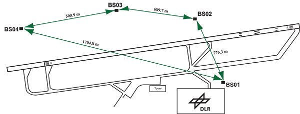
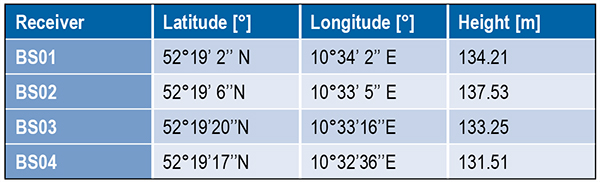
DLR has set up a GBAS prototype at the research airport in Braunschweig (ICAO identifier EDVE) near the DLR research facility there. This ground station has recently been updated and now consists of four GNSS receivers connected to choke ring antennas, which are mounted at heights between 2.5 meters and 7.5 meters above equipment shelters. All four receivers are capable of tracking GPS L5 (in addition to GPS L1 and L2 semi-codeless) and Galileo E1 and E5a signals. Figure 1 gives an overview of the current ground station layout, and Table 1 gives the coordinates of the antennas.
Figure 1. DLR ground facility near Braunschweig Airport, also shown in opening photo at left.Table 1. Ground receiver antenna coordinates.
Smoothing Techniques
The GBAS system corrects for the combined effects of multiple sources of measurement errors that are highly correlated between reference receivers and users, such as satellite clock, ephemeris error, ionospheric delay error, and tropospheric delay error, through the differential corrections broadcast by the GBAS ground subsystem. However, uncorrelated errors such as multipath and receiver noise can make a significant contribution to the remaining differential error. Multipath errors are introduced by the satellite signal reaching the antenna via both the direct path from the satellites and from other paths due to reflection. These errors affect both the ground and the airborne receivers, but are different at each and do not cancel out when differential corrections are applied.
To reduce these errors, GBAS performs carrier smoothing. Smoothing makes use of the less noisy but ambiguous carrier-phase measurements to suppress the noise and multipath from the noisy but unambiguous code measurements.
The current GBAS architecture is based on single-frequency GPS L1 C/A code measurements only. Single-frequency carrier smoothing reduces noise and multipath, but ionospheric disturbances can cause significant differential errors when the ground station and the airborne user are affected by different conditions. With the new available satellites (GPS Block IIF and Galileo) broadcasting in an additional aeronautical band (L5 / E5), this second frequency could be used in GBAS to overcome many current limitations of the single-frequency system.
Dual-frequency techniques have been investigated in previous work. Two dual-frequency smoothing algorithms, Divergence Free (Dfree) and Ionosphere Free (Ifree), have been proposed to mitigate the effect of ionosphere gradients.
The Dfree output removes the temporal ionospheric gradient that affects the single-frequency filter but is still affected by the absolute difference in delay created by spatial gradients. The main advantage of Dfree is that the output noise is similar to that of single-frequency smoothing, since only one single-frequency code measurement is used as the code input (recall that carrier phase noise on both frequencies is small and can be neglected).
Ifree smoothing completely removes the (first-order) effects of ionospheric delay by using ionosphere-free combinations of code and phase measurements from two frequencies as inputs to the smoothing filter. Unlike the Dfree, the Ifree outputs contain the combination of errors from two code measurements. This increases the standard deviation of the differential pseudorange error and thus also of the position solution.
Noise and Multipath in New GNSS Signals
GBAS users compute nominal protection levels (H0) under a fault-free assumption. These protection levels are conservative overbounds of the maximum position error after application of the differential corrections broadcast by the ground system, assuming that no faults or anomalies affect the position solution. In order to compute these error bounds, the total standard deviation of each differentially corrected pseudorange measurements has to be modeled. The standard deviation of the residual uncertainty (σn, for the nth satellite) consists of the root-sum-square of uncertainties introduced by atmospheric effects (ionosphere, troposphere) as well as of the contribution of the ground multipath and noise. In other words, these error components are combined to estimate σn2 as described in the following equation:
(1)
The ground broadcasts a value for σpr_gnd (described later in the section) associated with the pseudorange correction for each satellite. These broadcast values are based on combinations of theoretical models and actual measurements collected from the ground receivers that represent actual system characteristics. Unlike the ground, σpr_air is computed based entirely on a standardized error model. This is mainly to avoid the evaluation of multipath for each receiver and each aircraft during equipment approval.
In addition to the characteristics of nearby signal reflectors, multipath errors are mainly dependent on signal modulation and other signal characteristics (for example, power, chip rate). In earlier research, we showed that the newly available L5 signals broadcast by the GPS Block IIF satellites show better performance in terms of lower noise and multipath. This mainly results from an increased transmitted power and a 10 times higher chip rate on L5 compared to the L1 C/A code signal.
In this work, we extend this evaluation to the new Galileo signals and investigate their impact on a future multi-frequency, multi-constellation GBAS. Characterization of these new signals is based on ground subsystem measurements, since no flight data with GPS L5 or Galileo measurements are available at the moment. We assume that the improvements observed by ground receivers are also applicable to airborne measurements. This assumption will be validated as soon as flight data are available.
The measurements used were collected from the DLR GBAS test bed over 10 days (note that Galileo satellite ground track repeatability is 10 sidereal days) between the December 14 and 23, 2013. In that period, four Galileo and four Block IIF GPS satellites were operational and broadcast signals on both aeronautical bands E1 / L1 and E5a / L5.
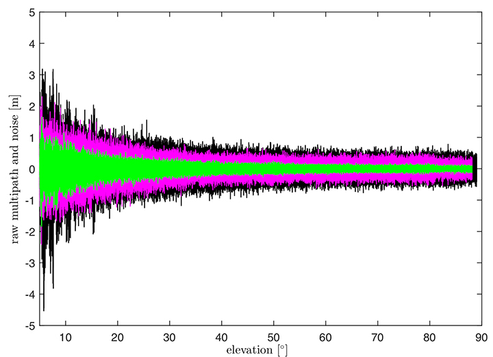
In Figure 2, the suppression of multipath and noise on the Galileo signals can be observed, where the code multipath and noise versus elevation for GPS L1 C/A BSPK(1), Galileo E1 (BOC (1,1)) and Galileo E5a (BPSK(10)) signals are shown. The code multipath and noise was estimated using the linear dual-frequency combination described in equation (2), where MPi represents the code multipath and noise on frequency i, ρi the code measurement, and ϕi,and ϕj represent the carrier-phase measurements on frequencies i and j, respectively. Carrier phase noises are small and can be neglected.
(2)
Figure 2. Raw multipath function of elevation for GPS L1, Galileo E1 (BOC (1,1)) and Galileo E5a (BPSK(10)) signals.
The multipath on the Galileo E1 (BOC(1,1)) signal (the magenta curve) is lower than the GPS L1 C/A (BPSK(1))(black curve), especially for low elevation, where the advantage of the E1 BOC(1,1) is more pronounced. The lower values can be explained by the wider transmission bandwidth on E1 and the structure of the BOC signal. Galileo E5a (green data in Figure 2) again shows a better performance than Galileo E1. This was expected due to the higher chip rate and higher signal power. A comparison of the raw multipath and noise standard deviations for GPS L1, L5 and Galileo E1, E5a signals is presented in Figure 3.
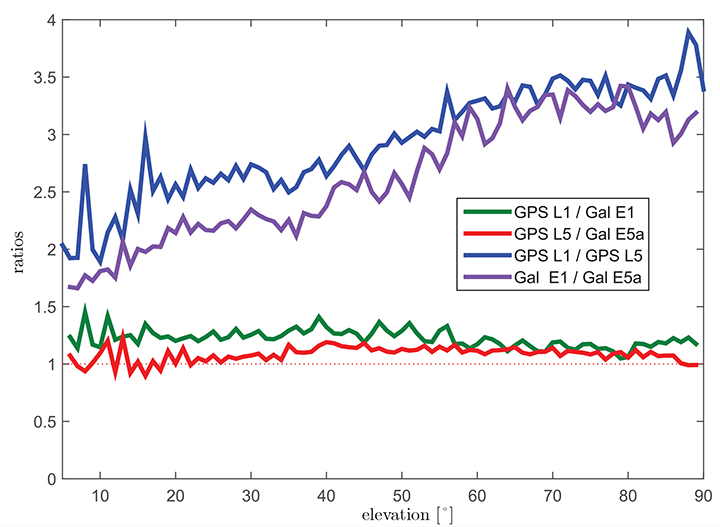
Figure 3. Ratios of the multipath and noise standard deviation function of elevation.
The curves there show the ratios of the standard deviations for each elevation bin. The values for GPS L1 are almost 1.5 times larger than those for Galileo E1 BOC(1,1) (green curve) for elevations below 20°. For high elevations, the ratio approaches 1.0. This corresponds to the observations in the raw multipath plot ( Figure 2). With the same signal modulation and the same chip rate, E5a and L5 have very similar results (red curve), and the ratio stays close to 1.0 for all elevations.
The blue and the purple curves in Figure 3 show the ratio of GPS L1 C/A (BPSK(1)) and GPS L5 (BPSK(10)), and Galileo E1 (BOC(1,1)) and Galileo E5a (BPSK(10)), respectively. The ratio of GPS L1 to GPS L5 (blue curve) increases with elevation from values around 2.5 for low elevations, reaching values above 3.5 for elevations higher than 60°. As Galileo E1 performs better, the ratio between Galileo E1 and Galileo E5a (purple curve) is smaller, from a value of 1.5 for elevations below 10 degrees to a value of 3.0 for high elevations.
Until now, we have presented the evaluation of raw code noise and multipath. However, in GBAS, carrier smoothing is performed to minimize the effect of code noise and multipath. The value that describes the noise introduced by the ground station is represented by a standard deviation called σpr_gnd and is computed based on the smoothed pseudoranges from the reference receivers. In the following section, we focus on the evaluation of σpr_gnd using different signals and different smoothing time constants. Note that, in this study, σpr_gnd contains only smoothed multipath and noise; no other contributions (for example, inflation due to signal deformation or geometry screening) are considered.
B-values and σpr_gnd
B-values represent estimates of the associated noise and multipath with the pseudorange corrections provided from each receiver for each satellite, as described in Eurocae ED-114A and RTCA DO-253C. They are used to detect faulty measurements in the ground system. For each satellite-receiver pair B(i,j), they are computed as:
(3)
where PRCTX represents the candidate transmitted pseudorange correction for satellite i (computed as an average over all M(i) receivers), and PRCSCA(i,k) represents the correction for satellite i from receiver k after smoothed clock adjustment, which is the process of removing the individual receiver clock bias from each reference receiver and all other common errors from the corrections. The summation computes the average correction over all M(k) receivers except receiver j. This allows detection and exclusion of receiver j if it is faulty. If all B-values are below their thresholds, the candidate pseudorange correction PRCTX is approved and transmitted. If not, a series of measurement exclusions and PRC and B-value recalculations takes place until all revised B-values are below threshold. Note that, under nominal conditions using only single-frequency measurements, the B-values are mainly affected by code multipath and noise.
Under the assumption that multipath errors are uncorrelated across reference receivers, nominal B-values can be used to assess the accuracy of the ground system. The standard deviation of the uncertainty associated with the contribution of the corrections (σpr_gnd) for each receiver m is related to the standard deviation of the B-values by:
(4)
where M represents the number of the receivers and N represents the number of satellites used. The final sigma takes into account the contribution from all receivers and is computed as the root mean square of the standard deviation of the uncertainties associated with each receiver (Equation 4).
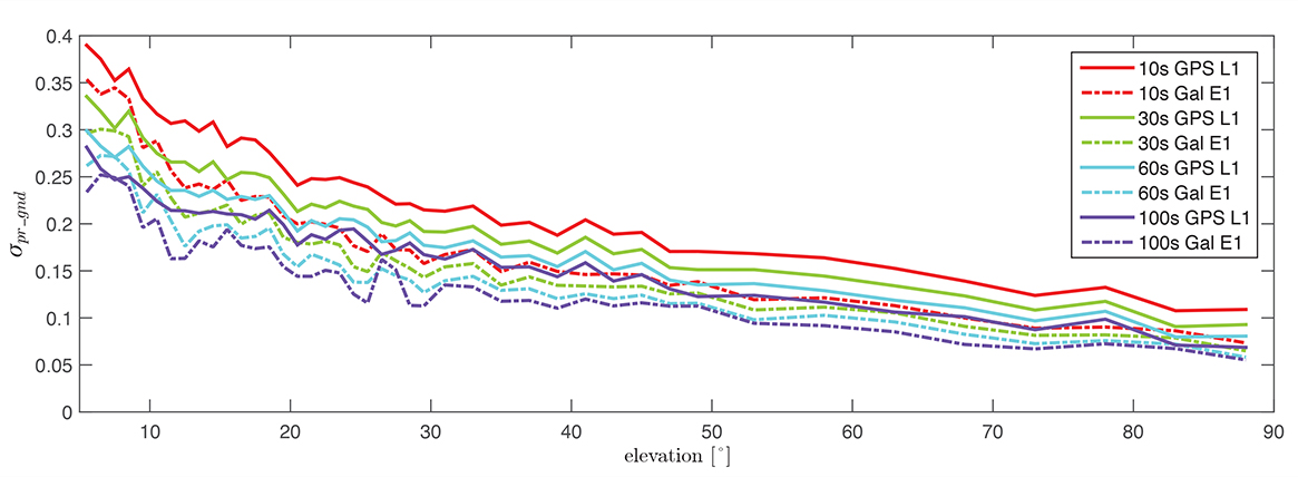
Figure 4 shows the evaluation of (σpr_gnd) for the Galileo E1, BOC(1,1) signal and the GPS L1 C/A signal for increasing smoothing time constants (10, 30, 60, and 100 seconds). Starting with a 10-second smoothing constant, Galileo E1 shows much better performance than GPS L1. The difference shrinks as the smoothing constant increases due to the effectiveness of smoothing in reducing noise and short-delay multipath. However, even with 100-second smoothing (the purple curves), Galileo E1 BOC(1,1) shows lower values of (σpr_gnd).
Figure 4. σ(pr_gnd) versus elevation for Galileo E1 (dotted lines) and GPS L1 (solid lines for different smoothing constants: red (10s), green (30s), cyan (60s), purple (100s).
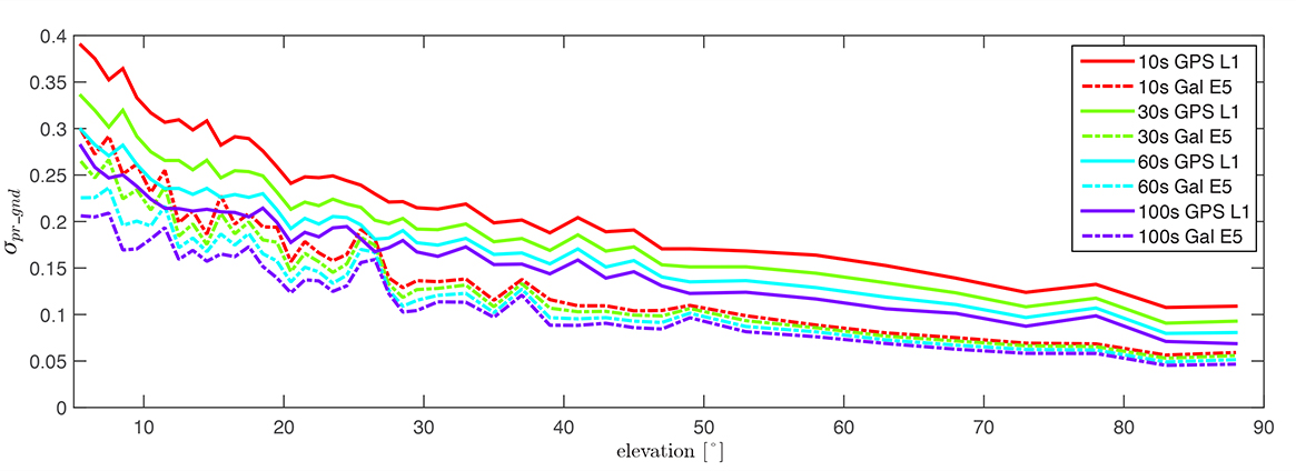
A similar comparison is presented in Figure 5, of the performance of GPS L1 and Galileo E5a. The Galileo E5a signal is significantly less affected by multipath, and the difference stays more pronounced than in the Galileo E1 – GPS L1, even with 100-second smoothing. It can be also observed that the Galileo signals have a lower sensitivity to the smoothing constant. The Galileo E1 signal shows an increase of sensitivity for low elevations (below 40°), while on E5a, a smoothing constant larger than 10 seconds has almost no impact on the residual error. Thus, a shorter smoothing constant on Galileo E5a generates approximately the same residual noise and multipath a 100-second smoothing constant on GPS L1.
Figure 5. σ(pr_gnd) versus elevation for Galileo E5a (dotted lines) and GPS L1 (solid lines) for different smoothing constants: red (10s), green (30s), cyan (60s), purple (100s).
The values for (σpr_gnd) are, however, impacted by the number of satellites which are used to determine a correction. Since only a very limited number of satellites broadcasting L5 and Galileo signals are currently available, these results should be considered preliminary. The first evaluations strongly indicate that with the new signals, we get better ranging performance. Based on the performance advantage of the new signals, a decrease of the smoothing constant is one option for future application. This would reduce the time required (for smoothing to converge) before including a new satellite or re-including a satellite after it was lost.
In the current GAST-D implementation, based on GPS L1 only, guidance is developed based on a 30-second smoothing time constant. A second solution, one with 100 seconds of smoothing, is used for deriving the Dv and Dl parameters from the DSIGMA monitor and thus for protection level bounding (it is also used for guidance in GAST-C). During the flight, different flight maneuvers or the blockage by the airframe can lead to the loss of the satellite signal.
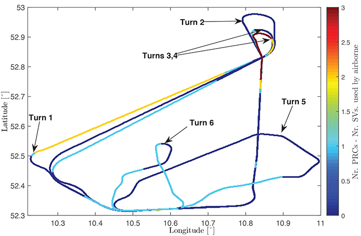
Figure 6 shows the ground track of a recent flight trial conducted by DLR in November 2014. The colors represent the difference between the number of satellites used by the ground subsystem (with available corrections) and the number of satellites used by the airborne subsystem in the GAST-D position solution. One of the purposes of the flight was to characterize the loss of satellite signals in turns. In turns with a steeper bank angle, up to 3 satellites are lost (Turns 1, 3, and 4), while on a wide turn with a small bank angle (Turn 2), no loss of satellite lock occurred. It is also possible for airframe to block satellite signals, leading to a different number of satellites between ground and airborne even without turns.
Figure 6. Ground track of a flight trial conducted by DLR. The colors represent difference between number of SVs used by the ground system and number of SVs used by the airborne.
With this in mind, a shorter smoothing constant would allow the satellites lost to turns or to airframe blockage to be re-included more rapidly in the position solution. However, a new smoothing constant would have to be validated with a larger amount of data. Data from flights trials has to be evaluated as well to confirm that similar levels of performance are reresentative of the air multipath and noise.
In a future dual-frequency GBAS implementation, an important advantage of lower multipath and noise is to improve the Ifree position solution. In earlier research, we demonstrated that the error level of the Dfree solution is almost the same as for single-frequency, but an increase in error by a factor of 2.33 was computed for the Ifree standard deviation based on L1 C/A code and L2 semi-codeless measurements.
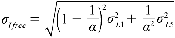
If the errors on L1 (E1) and L5 (E5a) code and carrier phase measurements are statistically independent the standard deviation of the σIfree can be written as,
(5)
where α=1−f 21 ∕ f 25, and σL1,σL5 represent the standard deviations of the smoothed noise and multipath for L1 (E1) and L5 (E5a), respectively. Considering σpr_gnd,L1(E1)) = σpr_gnd,L5(E5a)) in equation (5), the noise and multipath error on Ifree (σIfree) increases by a factor of 2.59.
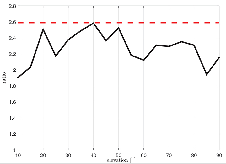
Figure 7 shows the ratio σIfree/σL1 using measured data. We observe that the measured ratio (the black curve) is below the theoretical ratio computed based on the assumption of statistically independent samples (the constant value of 2.59). This is explained by the fact that the multipath errors in the measurements are not independent but have some degree of statistical correlation. The standard deviations are computed based on the same data set used in the raw multipath and noise assessment using 100-second smoothed measurements sorted into elevation bins of 10° spacing.
Figure 7. Measured ratio σIfree/σL1 function of elevation.
Conclusion
We have shown how GBAS can benefit from the new signals provided by the latest generation of GPS and Galileo satellites. We have demonstrated improved performance in terms of lower noise and multipath in data collected in our GBAS test bed. When GBAS is extended to a multi-frequency and multi-constellation system, these improvements can be leveraged for improved availability and better robustness of GBAS against ionospheric and other disturbances.
Acknowledgment
Large portions of this work were conducted in the framework of the DLR internal project, GRETA.
Manufacturers
The ground facility consists of four JAVAD GNSS Delta receivers, all connected to Leica AR 25choke ring antennas.
Mihaela-Simona Circiu is is a research associate at the German Aerospace Center (DLR). Her research focuses on multi-frequency multi-constellation Ground Based Augmentation System. She obtained a 2nd level Specialized Master in Navigation and Related Applications from Politecnico di Torino.
MIchael Felux is is a research associate at the German Aerospace Center (DLR). He is coordinating research in the field of ground-based augmentation systems and pursuing a Ph.D. in Aerospace Engineering at the Technische Universität München.
Sam Pullen is a senior research engineer at Stanford University, where he is the director of the Local Area Augmentation System (LAAS) research effort. He has supported the FAA and others in developing GNSS system concepts, requirements, integrity algorithms, and performance models since obtaining his Ph.D. from Stanford in Aeronautics and Astronautics.
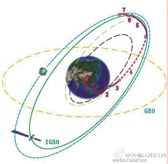
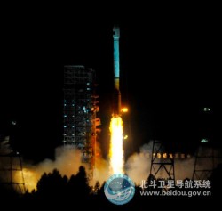
UPDATE (3/31/15): The BeiDou satellite is being targeted for an IGSO orbit, not a MEO orbit as previously speculated. The two images below make this clear.
Photo: BeiDouPhoto: BeiDou
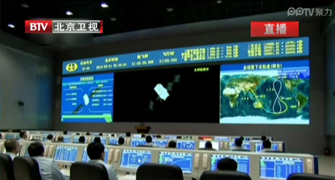
Below is a CCTV (China Central Television) news story covering the launch.
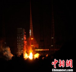
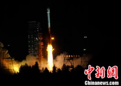
UPDATE (3/30/15): China’s launch of BeiDou-3 M1 is now being reported in that country’s media. The launch occurred at 21:52 on March 30. BeiDou-3 M1 is the first of 17 next-generation Beidou navigation satellites. It will have a new navigation signal system with inter-satellite links and other tests to verify the satellite navigation system.
NASA Spaceflight is reporting that China is believed to have launched the first of a new generation of navigation satellites for its BeiDou constellation. However, the launch has received a blackout in China, with lift-off only confirmed by local observers.
The possible launch of BeiDou-3 M1 took place at 13:52 UTC today from the Xichang Satellite Launch Center on a Chinese Long March 3C rocket, with the debut use of the new Expedition-1 (Yuanzheng-1) upper stage.
Today’s launch involved a new series of satellites that is expected to mark an advancement in the completion of its Beidou Phase III program several years ahead of schedule, by as soon as 2017 rather than 2020, NASA Spaceflight reports.
The Beidou Phase III system includes the migration of its civil Beidou 1 or B1 signal from 1561.098 MHz to a frequency centered at 1575.42 MHz – the same as the GPS L1 and Galileo E1 civil signals — and its transformation from a quadrature phase shift keying (QPSK) modulation to a multiplexed binary offset carrier (MBOC) modulation similar to the future GPS L1C and Galileo’s E1. The current (Phase II) B1 open service signal uses QPSK modulation with 4.092 megahertz bandwidth centered at 1561.098 MHz.
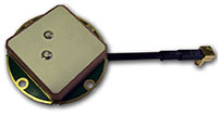
Tallysman Wireless announces the TW4421 and TW1421 antennas, which offer a step forward in performance for small GNSS antennas, the company said.
The TW4421 is a low-cost dual-feed magnetic mount antenna covering the GPS L1, GLONASS L1, Galileo and SBAS (WAAS, EGNOS & MSAS) frequency band (1574 to 1606 MHz). The TW4421 features a 25-millimeter dual-feed wideband patch element that provides excellent multipath rejection with a more linear carrier phase response, by virtue of a low axial ratio across the full frequency bandwidth, Tallysman said. It is especially suitable for high accuracy applications, and also offers high out-of-band signal rejection.
The TW4421 is housed in a compact IP67 magnetic mount enclosure and is available with a wide range of connector options.
The TW1421 embedded antenna is lightweight (30 gm) and features a very small footprint (35 mm diameter x 7.25 mm). The TW1421 is suited for use in applications where performance and small size are of paramount importance, such as extreme-sport-wearable tracking devices and UAVs.
“Most small low-cost GPS/GLONASS/Galileo antennas are narrow-band devices with an elliptically polarized response at the GPS and GLONASS frequencies,” said Gyles Panther CEO of Tallysman Wireless. “The TW4421/1421 antennas feature a 40-percent wider bandwidth patch, with a dual-feed structure, which provides unparalleled multipath rejection previously only available in much larger, more expensive antennas.”
UPDATE: The SVN65/PRN24 L5 transmitter has now been switched on. L5 is the civilian safety-of-life GPS signal, designed to meet demanding requirements for safety-of-life transportation and other high-performance applications.
UPDATE: The GPS Block IIF-3 satellite, SVN65, began transmitting L1 and L2 signals as PRN24 on October 8. A number of stations of the International GNSS Service are now tracking the satellite. The satellite is included in broadcast almanacs although it is set unhealthy and will continue to be so until satellite commissioning is completed. The satellite is still drifting towards its designated orbital position of Slot 1 in Plane A.
Meanwhile, SVN27/PRN27 was decommissioned from active service on October 6 and removed from the broadcast almanacs. However, the L-band
transmitters of SVN27 remain active, presumably for end-of-life testing.
UPDATE: According to Boeing, the satellite manufacturer, SVN65 is on orbit and performing as expected. A Boeing press release stated that “Controllers confirmed initial contact with the spacecraft at 11:43 a.m. Eastern time. The satellite’s GPS signals will be turned on and tested within a few days.”
Incidentally, the launch occurred exactly 55 years to the day after the launch of the world’s first satellite, Sputnik I, on October 4, 1957. It was Doppler tracking of that satellite that gave rise to the Transit navigation system and subsequently, its successor, GPS.
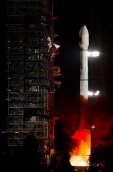
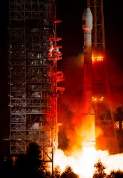
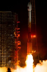
The launch of the GPS Block IIF-3 satellite took place as scheduled October 4 at 12:10 UTC (8:10 a.m. EDT), aboard a United Launch Alliance Delta IV rocket from Cape Canaveral, Florida. Spacecraft separation was reported at 16:27 UTC.
The Boeing-built spacecraft is designed to improve network coverage for both civilian and military networks, including a new L5 signal for improved commercial and civil aviation users.
The satellite, also known as SVN65, will be positioned in orbital slot 1, which is in plane A and will use the PRN24 ranging codes. Slot 1 was recently occupied by a Block IIA satellite, SVN39, operating as PRN09. SVN39 is one of the oldest operating satellites in the GPS fleet, having been launched on 26 June 1993. SVN39 underwent an initital Delta-V on September 27 to move it close to SVN38/PRN08 in slot 3 in plane A, making room for the new Block IIF satellite.
“Congratulations to the entire team on today’s successful launch of the GPS 2F-3 satellite,” Jim Sponnick, ULA vice president, Mission Operations, said in a post-launch press release.
“ULA and our mission partners have a rich heritage with the GPS program and we are proud to have served alongside the government and contractor teams over the last two decades to provide important Global Positioning System capabilities for our national defense and for millions of civilian and commercial users around the world.”
A Delta IV rocket lifts-off with an advanced GPS satellite from Cape Canaveral on Thursday. (Credit: ULA/Atkeison).
2. GPS SATELLITE SVN65 (PRN24) WAS LAUNCHED ON JDAY 278.
A USABINIT NANU WILL BE SENT WHEN THE SATELLITE IS SET ACTIVE TO
SERVICE.
3. POC: CIVILIAN – NAVCEN AT 703-313-5900, HTTP://WWW.NAVCEN.USCG.GOV
MILITARY – GPS OPERATIONS CENTER AT HTTPS://gps.afspc.af.mil/
GPSOC , DSN 560-2541,
COMM 719-567-2541, [email protected] , HTTP://gps.afspc.af.mil/GPSOC/GPS
MILITARY ALTERNATE – JOINT SPACE OPERATIONS CENTER, DSN 276-3514.
COMM 805-606-3514. [email protected]
Tallysman Wireless, Inc., has announced the latest addition of the TW4320/4322 to its line of antenna products. The TW4320/TW4322 antennas are small wide-band, high-performance antennas housed in a compact IP67 magnetic mount enclosure, with a three-meter cable and a wide range of connectors.
“Most small low-cost GPS and GLONASS antenna have narrow-band patch elements tuned mid-way, but which are 2-dB down in both signal bands,” said Gyles Panther, CEO of Tallysman Wireless. “The TW4320/22 antennas feature a patch element with a 40% wider bandwidth and a very low noise amplifier which together allows the full benefits of multi-constellational GNSS to be realized.”
The TW4320/TW4322 antenna covers the GPS L1, GLONASS L1, and SBAS (WAAS, EGNOS, and MSAS) frequency bands (1575 to 1606 MHz). It features a small patch element with 40 percent wider bandwidth than previously available in this format. It provides both GPS-L1 and GLONASS signals in the 1-dB received power bandwidth.
The TW4320/TW4322 has a two stage low-noise amplifier with a mid-section SAW (Surface Acoustic Wave). A tight pre-filter is available in the TW4322 to protect against saturation by high-level sub-harmonics and L-band signals.
Features:
• 40% wider bandwidth in the same format
• Axial ratio: 6 dB max
• Low noise LNA: 1 dB
• High rejection mid-section SAW filter
• Available pre-filter (TW4322)
• High gain: 28 dB typ.
• Wide voltage input range: 2.5 to 10 VDC
• IP67 weather-proof housing
Models:
• TW4320 – GPS/GLONASS antenna, three-meter cable, SMA Male 32-4320-xx-yyyy
• TW4322 – GPS/GLONASS antenna, with pre-filter, three-meter cable, SMA Male 32-4322-xx-yyyy
Two British technologists backed by the U.K. Ministry of Defense have filed patents on the future interoperable GPS and Galileo signal designs that severely disrupt modernization plans for both systems and suddenly, unexpectedly place receiver manufacturers in a highly uncertain and unfavorable situation. Some of the patents have been granted in the U.K. and in Europe, and applications are pending in U.S. patent court, with a ruling expected at any time.
Companies in the United States and outside the country are being approached and asked to pay royalties, on the basis of the patent filings, for use of the European E1 Open Service signal and the modernized GPS L1C signal. Should such initiatives prevail, costs would presumably be passed along to end users of GPS and Galileo — the same taxpayers who have already paid once for the systems.
The purveyor of the royalty solicitations is Jim Ashe, vice president for sales and intellectual property at Ploughshare Innovations Ltd., Hampshire, UK. The patents, if successfully used to collect fees from satellite manufacturers or receiver manufacturers, would have a chilling effect on the use of the new interoperable signals that all parties have labored so hard, for so long, to design. They could quite possibly lead to a return to a BOC(1,1) structure for these signals, losing the benefits of MBOC.
“There’s quite an argument going on,” said one person familiar with the controversy. “Some of the methods of arguing have not been too kind.”
The Background. A great deal of work was accomplished cooperatively between the United States and the European Union (EU) to develop the landmark 2004 signal agreement that emerged from the Galileo Signal Task Force, formalizing cooperation on satellite navigation between the United States and more than two dozen European countries, including the U.K. Part of that agreement concerned a common signal structure (spectrum) for the civilian signals for both the E1 Open Service (OS) signal — the Galileo equivalent of GPS L1 — and the new U.S. GPS L1C signal to be implemented on the GPS III satellites, coming as early as 2015.
The EU said during that process, in effect, “Even though we have agreed on this, Europe wants to be able to optimize the E1 OS signal beyond the agreement on that civilian signal being a binary offset carrier BOC(1,1) signal.” Both international entities had agreed that would be the waveform or the spectrum of the new signal.
The Europeans began to evaluate methods of optimizing their signal. They had some designs called composite binary coded symbols (CBCS), a mechanism of putting a higher frequency componenent into the signal structure, and also a version called CBCS*, meaning that they found there was a bias generated by that extra signal, and so they had to invert every other one of its repetitions.
The signal structure that they were playing with was centered on a plus and a minus 5-MHz component. (Actually five times 1.023, because of the inherent clock of GPS, you can think of it as 1.023 MHz. Everyone in doing compatible or interoperable signals agreed upon that; when reference is made to 5 or 10 MHz, or an even 5 or an even 10, it means that number multiplied by 1.023).
The Europeans were were putting an additional BOC signal on top of the BOC 1,1, and it would have plus or minus 5 MHz as the centers of those two BOC peaks, and then some kind of waveform to modulate that.
The United States pushed back against that to some degree, and proposed adoption of the so-called MBOC waveform, in which case the U.S. signal was equally optimized with a concept called time-multiplexed BOC (TMBOC). The Europeans used the CBOC approach. So, very different ways of doing this. In the European way, they transmitted a continuous but very low-power BOC(6,1) term. The U.S approach transmits four BOC(6,1) chips out of every 33 chips of code (see “Future Wave” sidebar).
A chip in this case means a part of the spreading code, so each signal has its spreading codes, just like the C/A code is a spreading code, meaning a pseudorandom code modulating the carrier. L1C and E1 OS have a pseudorandom spreading code.
The U.S. approach does not put BOC(6,1) components onto the data; that’s what is commonly called MBOC. The U.S. approach is TMBOC, on the pilot carrier only, not on the data component. The European system is like two separate signals, the BOC(1,1) signal having both pilot and data, and a BOC(6,1) signal having both pilot and data. They’ve put the (6,1) into both data and pilot components.
Cue the Antagonists. Part of the task force from Europe and the United States considering the future signals’ make-up were Tony Pratt and John Owen, who works for the U.K. Ministry of Defense and whose office sponsored Pratt’s work. The two participated heavily in all these signal discussions. They stated in early meetings they planned to file patents in some areas.
“Frankly,” states one source, “people should have paid more attention when they said that, and asked ‘What do you mean, and how’s it going to work, etcetera?’ And secondly, there probably should have been a written agreement between parties that nobody will take advantage or patent any of these ideas that we are developing.”
Pratt and Owen filed a number of patents domestically, in the U.K., and and in the European Union, in 2003 and in 2006, and in other places around the world, such as Japan, Canada, and in the United States as well. Some of the U.K. and European patents have been granted. The first of some of those U.S. patents may be issued in the near future.
The original patent filings were later amended to include new claims. The new claims were much more specifically oriented toward TMBOC and CBOC, whereas the original claims were more generally oriented toward modulated methods. The claims have been modified over the years; this is fairly standard patent practice.
As a result, the original 2003 patent doesn’t necessarily read on a particular signal, but its early filing date has precedence. The claims have been updated and modified, and if the patent office issues those, as a true patent, then the new claims apply. Plenty of big patent battles have been fought over just such issues.
Once the patent is issued, a satellite or receiver manufacturer must assume that it is valid, and has only two responses to make, other than acquiescing to royalty claims. The manufacturer can either say, if building a product, “No, my product does not infringe, and I will prove that it doesn’t.’” The other choice for manufacturers is to go back into the patent office and sue the patent filer (and grantee) in the patent courts and prove that the patent was invalid in the first place that the patentee should not have been granted it.
The United States and others were taken off-guard when the U.K. company Ploughshare, which is owned and controlled by a part of the British MoD called Defense Science and Technology Laboratory (DSTL), started making claims on manufacturers. The DSTL is similar to the U.S. Defense Advance Research Products Agency (DARPA), which is credited with inventing the Internet. If taxpayer money goes into something new and interesting, it is considered in some circles legitimate to file patents on those and attempt to recover taxpayer money through royalties on that taxpayer investment. That concept is not being challenged. Questions as to whether the patents are legitimate are very much in discussion.
Ploughshare has contacted companies, saying, “If you use these signals coming from either the European satellites or the U.S. satellites, we will go after companies using these signals.” There are different patents issued, one by the European Patent Office, applying to most of the EU countries, that applies directly to the TMBOC signal, the E1 OS signal, and possibly also to Europe’s E5 signal, which is E5a and E5b; and there is also a patent for GPS III, the L1C signal.
“If you take the patent that hits TMBOC, and you take the broadest possible interpretation of that patent against receiver companies, it says: if you bring into your antenna and process that signal, whether you use all parts of it or not, for instance if you use the BOC(1,1) and not the BOC(6,1) part — then you infringe the patent. Others argue that if you don’t use both components, you don’t infringe.
“But the claim is written broadly enough that it would apply to any receiver receiving and processing the signal. Nobody says what processing means. The patent says if you receive and process the TMBOC signal, as defined in the prior claim, you infringe the patent.
“There is confusion as to whether that will apply or not apply — some people expect that it doesn’t and some people think that it might. That’s up in the air.”
George Is Getting Upset. Various factions in the United States are upset by and trying to figure out what to do about the impasse. From a government point of view, there are three paths that the U.S. government can follow:
Put pressure on the U.K. diplomatically. That would be up to the State Department to put pressure on the EU or the U.K. in particular. The EU and the continental Europeans are equally furious at the British for doing this, as far as parties in the U.S. understand. This can’t be stated as a fact but is widely understood and thought to be the case. The diplomatic approach has its limits, obviously.
Go into Europe and fight the patents in European patent court and try to prove them invalid, to invalidate the patents. Companies could do the same thing, go into various courts, whether they be U.S. or European or Japanese, and say: “Our receivers don’t infringe,” and then have to prove that to the court; or say “The whole patent should not have been allowed, and I’ll fight the legitimacy of the patent.”
Some believe — and there is controversy and anger on this point — that, just as Galileo’s IOV satellites have the capability to transmit without the BOC(6,1) component, the United States should be able to do that with the GPS III satellites as well. Because if the signal is not there, and if the receivers are therefore not designed to process the signals that are not there, then the patent no longer has any relevance.
“If we are to turn off the BOC(6,1) term for a period of time until the legal or diplomatic or other approaches worked, then we would be able to turn the BOC(6,10) term back on again, and return to the original agreed MBOC and TMBOC signals. That requires some coordination between the United States and Europe, and it requires some work to make that possible in the GPS III satellites, putting a switch in the GPS III satellites to permit the operators to turn that (6,1)BOC on and off. This is being hotly debated.”
Some parties object, stating that L1C is too important a signal to mess with, and this proposal runs the risk of slowing down the program, and/or making it more expensive. They believe strongly that the off/on switch is not the best or most far-sighted option: why should the United States be forced to change its signal design due to an illegitimate patent, and in the end wind up with a less capable system?
It is not publicly known whether the Air Force is or is not looking into that option.
During the week of June 25 there was Working Group-A meeting in Washington D.C. followed by a plenary meeting between the EU and United States. The patent controversy was presumably discussed in some fashion, but whether formally addressed or lurking in the background is unknown at this time.
“There is some naivete around this,” said the magazine’s soure. “It’s a serious threat. People think maybe they’ll only go after the high-end receivers, and maybe the royalties won’t be so bad. Ploughshare is trying to lull people into a false sense of security. The impact of this will be great unless it is defeated.”
“The L1C waveform originally was to have been a pure BOC(1,1) (a 1.023 MHz square wave modulated by a 1.023 MHz spreading code). Negotiations between the U.S. and the European Union (EU) at that time resulted in an agreement that both GPS and Galileo would use a baseline BOC(1,1) signal. However, the EU reserved the right to further optimize their signal within certain bounds. Some of the optimization proposals were known as CBCS and CBCS*. However, in further EU/US discussions it was decided that L1C and the Galileo E1 open service signal should have identically the same spectrum. This was a significant challenge because of different baseline signal structures and existing designs.
“The breakthrough came when [U.S. representative] John Betz proposed what is called MBOC. The MBOC waveform has 10/11th of its power in BOC(1,1) and 1/11th in BOC(6,1). However, L1C and E1 OS achieve this result in very different ways. The Galileo technique is called CBOC. The GPS technique is called TMBOC. Whereas Galileo has a 50/50 power split between pilot and data and includes the BOC(6,1) component in each, GPS includes the BOC(6,1) waveform only in the pilot component by modulating four of every 33 spreading code chips with a 6 MHz square wave and 31 chips with a 1 MHz square wave. With 75 percent of the power in the pilot, the result is 3/4 x 4/33 or 1/11, as required. It is likely the BOC(6,1) signal component will be ignored by consumer-grade GNSS receivers where a narrow RF bandwidth is preferred. Fortunately that is a loss of only 12 percent (0.56 dB) of the L1C pilot power. However, for commercial and professional grade receivers, the extra waveform transitions (wider Gabor bandwidth) can be used to improve code tracking signal-to-noise ratio, and with certain advanced techniques it should be possible to improve multipath mitigation. This final point depends on careful control or calibration of the transmitted code timing and symmetry.”
EGNOS and Galileo IOV Satellites Shift Right
The next EGNOS satellite, originally scheduled for a June 18 launch, now has a rise date of July 7 from Baikonur Cosmodrome in Kazakhstan. The launch was delayed by a problem with a first-stage subsystem on the Proton rocket. SES-5 is also known as Sirius 5, stemming from the development of the Sirius satellite constellation by Nordic Satellite AB, now owned by Luxembourg’s SES.
The satellite carries a transponder for the European Geostationary Navigation Overlay Service (EGNOS). The transponder is intended to eventually replace or one of those on the currently used EGNOS satellites (Inmarsat 3-F2 at 15.5 degrees west using PRN 120, Artemis at 21.5 degrees east using PRN124, and Inmarsat-4-F2 at 25 degrees east using PRN 126 and designated for industry tests).
Unlike the present L1-only EGNOS satellites, SES-5 will have transponders on both L1 and E5 frequencies similar to the Wide Area Augmentation System satellites, which broadcast on L1 and L5.
SES-5 is to be stationed at 5 degrees east longtiude.
A second SES satellite with EGNOS transponders is under construction. The SES Astra 5B satellite is scheduled for launch in the second quarter of 2013 and will be positioned at SES Astra’s 31.5 degrees east orbital position.
Role Switch. On March 22 and 23, Inmarsat-4-F2 at 25 degrees east using PRN126 and Artemis at 21.5 degrees east using PRN124 switched roles. PRN126 became an EGNOS operational signal-in-space satellite, while PRN124 became the test satellite, transmitting message type 0. PRN120 and PRN126 returned to service around 17:00 UTC on Tuesday, June 26.
According to an EGNOS service announcement dated April 3, the switch was due to the aging state of the Artemis satellite.
Galileo October Birds. According to a usually reliable source, the launch date for the second set of Galileo IOV satellites, previously announced as September 28, has been pushed back a couple of weeks to October 12.


 Tallysman Wireless, Inc., has announced the latest addition of the TW4320/4322 to its line of antenna products. The TW4320/TW4322 antennas are small wide-band, high-performance antennas housed in a compact IP67 magnetic mount enclosure, with a three-meter cable and a wide range of connectors.