The LightSquared/Ligado Networks saga, now in its second decade, continues. On Sept. 9, the Committee to Review FCC Order 20-48 Authorizing Operation of a Terrestrial Radio Network Near the GPS Frequency Bands of the National Academies of Sciences, Engineering and Medicine (NASEM) released its consensus study. Both sides claim the report supports their position.
According to Ligado, the report confirms the FCC’s finding that the company’s operations “can co-exist with GPS.” It cited the report’s conclusion that “the technology to enable compatibility has been in use for over a decade, and most consumer equipment, commercial general navigation, timing, cellular and aviation receivers will not experience harmful interference from Ligado’s operations.”
The NASEM report also confirmed, the company said, the FCC’s finding that “[a] small percentage of very old and poorly designed GPS devices may require upgrading.” Ligado reaffirmed its commitment to “upgrade or replace” federal equipment negatively impacted by its operations and expressed its hope that now the Department of Defense (DOD) and the National Telecommunications and Information Administration “will stop blocking Ligado’s license authority and focus instead on working with Ligado to resolve potential impacts relating to all DOD systems.”
By contrast, the GPS Innovation Alliance applauded the NASEM’s “reaffirmation that Ligado’s terrestrial operations would have a harmful, real-world impact on the millions of federal and commercial users that rely on GPS, satellite communications, and weather forecasting services every single day.” It further stated that the report “demonstrates that Ligado would pose an unacceptable risk to services critical to safety-of-life operations, our national security, and our economy” and urged “government action to address the imminent, but preventable, harm that would result from Ligado’s deployment.”
According to the DOD, the NASEM study “confirms that Ligado’s system will interfere with DOD GPS receivers, which include high-precision GPS receivers.” The study also concludes, DOD says, that the FCC’s proposed mitigation and replacement measures “are impractical, cost prohibitive, and possibly ineffective.”
The NASEM committee pointed out repeatedly in its report that matters are more nuanced than represented by either side and that test results and harmful interference depend on many factors — including the receiver’s signal processing architecture, the amount of SNR loss, the use case, and the relevant failure modes. “The determination of harmful interference is dependent on the particulars,” it said.
The committee also bemoaned “a lack of a quantifiable definition of harmful interference” and “the lack of common receiver assumptions” and called for “more definitive receiver standards.” It also pointed out that “many spectrum conflicts could be avoided if receivers were better designed and implemented.”
The GPS user base is in the billions. Therefore, even if “most” receivers will not be harmed by Ligado’s operations, as the committee reported, tens of millions of devices will be. I highly recommend reading the full report.
The U.S. Defense Logistics Agency has executed a $316 million contract option for BAE Systems’ advanced M-code GPS modules, raising the contract funding to $641 million.
The modules provide dependable positioning, navigation, and timing for ground troops, vehicles, aircraft and precision munitions. The contract will ensure the availability of Common GPS Modules (CGM) for advanced military GPS receivers with anti-jamming and anti-spoofing capabilities that enable operation in contested environments.
Under the contract option executed in November, BAE Systems will manufacture CGMs for future ground, airborne and weapon GPS receivers for the U.S. Department of Defense (DoD) and its allies. The award builds on a May $325 million contract and enables BAE Systems to continue to meet domestic and international demand for Military GPS User Equipment (MGUE) Increment 1 M-Code modules in GPS receivers through the end of the decade.
“Military operations require assured positioning, navigation and timing, and our customers are shifting to M-code to harden their GPS receivers against jamming and spoofing,” said Frank Zane, Navigation and Sensor Systems business development director at BAE Systems. “We’re ready to meet this need today with secure, reliable M-code GPS solutions, and we’re developing the next-generation of solutions to stay ahead of the threat.”
BAE Systems is delivering two advanced M-code GPS receivers: the Miniature Precision Lightweight GPS Receiver Engine – M-Code and the NavStrike-M GPS receiver.
Deliveries of the ultra-small MicroGRAM-M are expected in 2022, and deliveries of the Strategic Anti-jam Beamforming Receiver – M-Code are expected in 2024.
BAE Systems has received a $247 million contract from the U.S. Space Force’s Space and Missile Systems Center to design and manufacture an advanced military GPS receiver and next-generation semiconductor.
The technology will provide positioning, navigation, and timing (PNT) capabilities to warfighters so they can execute missions in challenging electromagnetic environments.
The Military GPS User Equipment (MGUE) Increment 2 Miniature Serial Interface program will provide improved capabilities for size-constrained and power-constrained military GPS applications, including precision-guided munitions and battery-powered handheld devices.
The program will focus on the certification of an advanced application-specific integrated circuit (ASIC) and the development of an ultra-small, low-power GPS module.
Both products will work with the next-generation military M-code signal technology, which provides reliable GPS data with anti-jamming and anti-spoofing capabilities to protect against electronic warfare threats.
“This program enables us to further develop our core M-code technology to deliver high-performance, next-generation GPS capabilities,” said Greg Wild, director of Navigation and Sensor Systems at BAE Systems. “Our M-code receiver and next-gen ASIC will enable secure and reliable military GPS capabilities in a broader range of platforms.”
BAE Systems’ Precision Strike business has 45 years of military GPS experience and more than 1.5 million GPS devices on over 280 platforms around the world. The company is currently producing M-code GPS receivers in multiple form factors, including a low power, small form factor M-code solution.
Additional prototypes are in development for ground, weapons and airborne mission applications, and the company’s M-code GPS products are available to U.S. allies via foreign military sales.
Work on the program will be conducted at the company’s facility in Cedar Rapids, Iowa.
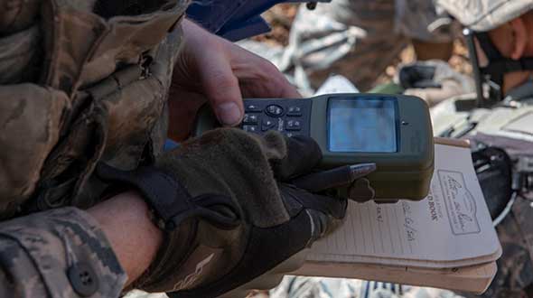
Feature image: An Airman with the 374th Security Forces Squadron uses a Defense Advanced GPS Receiver (DAGR) to track the team’s current during a 2018 field training exercise at Camp Fuji, Japan. (Photo: Senior Airman Matthew Gilmore/U.S. Air Force)
Ensuring the freedom to continue innovating is vital to our global economy, job creation and ultimately to empowering the next generation of GPS-enabled applications.
GPS — it’s a household name and has come to benefit so many aspects of our day-to-day lives. Today across the globe, it is estimated that there are more than 3 billion GPS receivers in the marketplace. Included in this total are GPS receivers found in mobile phones, automobiles, airplanes, tractors, boats and high-precision surveying equipment, to name just a few examples. In the past decade alone, GPS applications like these have helped generate more than $1.2 trillion for the U.S. economy and millions of jobs.
So how did GPS become so ubiquitous? Thanks to the leadership of the United States Air Force, which maintains and operates the GPS constellation, and long-standing U.S. policy, which makes GPS available as a vital public resource, any private sector company can design and build a receiver capable of listening for these GPS signals, without seeking the government’s approval or paying user fees. This freedom to innovate is at the heart of why GPS has been so successful and continues to drive innovation across our economy.
With the freedom to innovate, GPS receiver manufacturers have developed a range of advanced technologies to address market needs from the simple to the highly complex. These technologies reflect the inherent functional and technical differences between radio communications services and a navigation service like GPS.
Huge range of technologies. GPS receiver innovations enable a receiver to listen for a GPS signal that is less than a millionth of a billionth of a watt, while simultaneously resisting interference that is 10,000 times greater. Whether the GPS receiver is found in a tiny smartwatch or a 20-ton tractor, what they have in common is the ability to convert a faint radio signal into what we most commonly recognize as our current location displayed as a blue dot. They do this remarkably well.
Today’s regulatory landscape also correctly recognizes that every GPS-enabled application has unique requirements driven by intended function, environment and design factors. For example, a GPS receiver used for synchronizing financial transactions has different demands from a GPS receiver found in an autonomous vehicle. The former focuses on timing while the latter needs precise positioning to help maintain lane-level guidance.
Similarly, high-precision surveying equipment capable of delivering centimeter-level accuracy will no doubt have different receiver and antenna requirements than those found in a typical smartphone. The freedom to innovate enables GPS receiver manufacturers to support this market differentiation.
GPS resiliency. With many of our nation’s key critical infrastructure sectors dependent on GPS, there has been increasing discussion in Washington about the resiliency of GPS. Some have specifically expressed concern that a GPS jamming or spoofing attack could disrupt these key services and have advocated for new requirements on GPS receivers.
To be clear, GPS jammers and spoofers are illegal devices, designed specifically to interfere with GPS signals, either blocking the signal outright or emitting a fake signal in order to falsify one’s location. In either scenario, this interference occurs within a localized area from a detectable source. So, the reality is that mandates won’t stop a malicious actor intent on illegally interfering with GPS or another wireless technology, but vigorous enforcement of U.S. federal law can.
It is also important to remember that the GPS satellites are a multi-use U.S. military-civilian asset, supporting the mission of our armed forces, and have therefore been built with the highest levels of security and redundancy. Any attempts to attack the GPS constellation risks impacting not just civil services but the military signal as well.
Mission-critical applications. When it comes to resiliency, open innovation enables GPS receiver manufacturers to work with mission-critical application providers to develop products designed to meet their specific requirements. Different categories of users can and should define and specify performance and resiliency requirements appropriate for their applications.
For example, the requirements for a military GPS receiver are much more demanding than those for the receiver in an IoT device that reports its position hourly or daily. A military GPS receiver will, therefore, be significantly more expensive than an IoT receiver. Conversely, those who deploy internet of things (IoT) receivers will require low price points to support ubiquitous applications.
GPS manufacturers and applications developers have responded to market requirements by providing new and innovative techniques for increasing resilience, including designing receivers capable of receiving signals from multiple GNSS systems. This is the best way to ensure resilience — via application-specific requirements that are driven by customers who are most knowledgeable about their needs, not by general regulations or government fiat.
Preserving signal access. At the same time, the government does have a responsibility to investigate and take the necessary enforcement action to preserve unhindered reception of GPS signals. Vigorous enforcement of federal law by the Federal Communications Commission (FCC) and other government agencies — which already prohibits the manufacture, importation, marketing, sale and operation of GPS jammers — can keep these illegal devices out of the hands of those seeking to disrupt GPS operations. Such enforcement is critical to protecting our military operations, aviation and other safety-of-life applications.
Over the past three decades, worldwide adoption of robust, innovative GPS receivers attests to the trust users have placed in GPS as the gold standard for availability, accuracy, reliability and resiliency. Ensuring the freedom to continue innovating is vital to our global economy, job creation and ultimately to empowering the next generation of GPS-enabled applications.
About the GPS Innovation Alliance
The GPS Innovation Alliance was founded by Deere & Company, Garmin International Inc. and Trimble Inc. The Alliance recognizes the ever-increasing importance of GPS and other GNSS technologies to the global economy and infrastructure and is firmly committed to furthering GPS innovation, creativity and entrepreneurship. The GPS Innovation Alliance seeks to protect, promote and enhance the use of GPS. For more information, visit www.gpsalliance.org or follow @GPS4Life.
J. David Grossman serves as executive director of the GPS Innovation Alliance (GPSIA), an organization dedicated to protecting, promoting and enhancing the use of GPS. Prior to joining GPSIA, Grossman spent nearly a decade in public service, including as chief of staff to FCC Commissioner Mignon Clyburn; legislative director and senior advisor for technology policy to Rep. Anna Eshoo of Silicon Valley; and as technology counsel to the U.S. House Small Business Committee under the leadership of Rep. Nydia Velázquez.
Grossman holds a Master’s Degree in Public Policy from George Mason University and a B.A. in Political Communication from George Washington University’s School of Media and Public Affairs.
Capt. Adam Moody, 2 SOPS GPS Operations Support flight commander, and Staff Sgt. Carl Ellinger, 2 SOPS GPS mission chief, review a checklist of procedures for a transfer operation at Schriever Air Force Base. (Photo: U.S. Air Force photo/Dennis Rogers)
The 2nd Space Operations Squadron (2 SOPS), based at Schriever Air Force Base, will implement the GPS Issue of Data, Clock software modification this summer in accordance with established guidance, according to Rick Hamilton, CGSIC Executive Secretariat, U.S. Coast Guard Navigation Center.
The modification is in compliance with GPS Interface Specifications IS-GPS-200, which is published for manufacturers to ensure continued device compatibility.
As the largest Department of Defense spacecraft constellation, operators must modify processes, software and operations to meet the ever-growing demand for GPS signals. The squadron conducts software modifications regularly to support the constellation.
The modifications are primarily transparent to users, specifically those with IS-GPS-200 compliant devices. Users who experience issues with their devices or receivers should contact the manufacturer to troubleshoot the problem.
The U.S. Coast Guard Navigation Center provides information and services to civil GPS users. They can be contacted at 703-313-5900 or online.
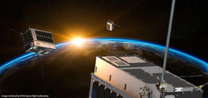
Space Flight Laboratory (SFL) has launched three formation-flying HawkEye 360 Pathfinder 15-kilogram, 20 x 27 x 44-centimeter microsatellites designed to detect and geolocate radio frequency (RF) signals.
Hawkeye 360 Pathfinder satellite trio flies in formation, seeking RF signals from Earth. (Image: UTIAS Space Flight Laboratory)
The target signals emanate from VHF radios, maritime radar systems, automatic identification system (AIS) beacons, very small aperture terminal (VSAT) communication systems and emergency beacons. HawkEye 360 applies advanced RF analytics to the data to assess suspicious vessel activity, survey communication frequency interference and direct search-and-rescue.
Precise formation flying is critical, as the relative position of each satellite must be known to accurately geolocate transmission sources. The satellites carry space-qualified GPS receivers and high-performance attitude control systems to keep them stable in orbit.
Flying in formation, two or all three satellites may receive the same transmission when it originates from their common footprint. The signal’s different times of arrival at each satellite and their different apparent center frequencies (Doppler) will enable onboard comparison of time-of-arrival and frequency-of-arrival measurements to then calculate the transmitter’s position.
The onboard GPS receivers provide precise estimates for the position and velocity of the receivers, information required for multilateration. The satellites further synchronize their clocks using GPS receivers, which also stabilize the phase-locked loops governing the tuning frequency in the RF tuners.
The satellites were built by Deep Space Industries of San Jose, California, and University of Toronto, Institute for Aerospace Studies/Space Flight Laboratory (UTIAS/SFL). They were launched in December 2018 into low-Earth orbit.
Tests of the robustness of commercial GNSS devices against threats show that different receivers behave differently in the presence of the same threat vectors. A risk-assessment framework for PNT systems can gauge real-world threat vectors, then the most appropriate and cost-effective mitigation can be selected.
Vulnerabilities of GNSS positioning, navigation and timing are a consequence of the signals’ very low received power. These vulnerabilities include RF interference, atmospheric effects, jamming and spoofing. All cases should be tested for all GNSS equipment, not solely those whose applications or cargoes might draw criminal or terrorist attention, because jamming or spoofing directed at another target can still affect any receiver in the vicinity.
GNSS Jamming. Potential severe disruptions can be encountered by critical infrastructure in many scenarios, highlighting the need to understand the behavior of multiple systems that rely on positioning, and/or timing aspects of GNSS systems, when subject to real-world GNSS threat vectors.
GNSS Spoofing. This can no longer be regarded as difficult to conduct or requiring a high degree of expertise and GNSS knowledge. In 2015, two engineers with no expertise in GNSS found it easy to construct a low-cost signal emulator using commercial off-the-shelf software–defined radio and RF transmission equipment, successfully spoofing a car’s built-in GPS receiver, two well-known brands of smartphone and a drone so that it would fly in a restricted area.
In December 2015 the Department of Homeland Security revealed that drug traffickers have been attempting to spoof (as well as jam) border drones. This demonstrates that GNSS spoofing is now accessible enough that it should begin to be considered seriously as a valid attack vector in any GNSS vulnerability risk assessment.
More recently, the release of the Pokémon Go game triggered a rapid development of spoofing techniques. This has led to spoofing at the application layer: jailbreaking the smartphone and installing an application designed to feed faked location information to other applications. It has also led to the use of spoofers at the RF level (record and playback or “meaconing”) and even the use of a programmed SDR to generate replica GPS signals — and all of this was accomplished in a matter of weeks.
GNSS Segment Errors. Whilst not common, GNSS segment errors can create severe problems for users. Events affecting GLONASS during April 2014 are well known: corrupted ephemeris information was uploaded to the satellite vehicles and caused problems to many worldwide GLONASS users for almost 12 hours. Recently GPS was affected. On January 26, 2016, a glitch in the GPS ground software led to the wrong UTC correction value being broadcast. This bug started to cause problems when satellite SVN23 was withdrawn from service. A number of GPS satellites, while declaring themselves “healthy,” broadcast a wrong UTC correction parameter.
Atmospheric Effects. Single frequency PNT systems generally compensate for the normal behavior of the ionosphere through the implementation of a model such as the Klobuchar Ionospheric Model.
Space weather disturbs the ionosphere to an extent where the model no longer works and large pseudorange errors, which can affect position and timing, are generated. This typically happens when a severe solar storm causes the Total Electron Count (TEC) to increase to significantly higher than normal levels.
Dual-frequency GNSS receivers can provide much higher levels of mitigation against solar weather effects. However, this is not always the case; during scintillation events dual frequency diversity is more likely to only partially mitigate the effects of scintillation.
Solar weather events occur on an 11-year cycle; the sun has just peaked at solar maximum, so we will find solar activity decreasing to a minimum during the next 5 years of the cycle. However that does not mean that the effects of solar weather on PNT systems should be ignored for the next few years where safety or critical infrastructure systems are involved.
TEST FRAMEWORK
Characterization of receiver performance, to specific segments within the real world, can save either development time and cost or prevent poor performance in real deployments. Figure 1 shows the concept of a robust PNT test framework that uses real-world threat vectors to test GNSS-dependent systems and devices.
OPENING GRAPHIC
FIGURE 1. Robust PNT test framework architecture.
Figure 2. Detected interference waveforms at public event in Europe.
We have deployed detectors — some on a permanent basis, some temporary — and have collected extensive information on real-world RFI that affects GNSS receivers, systems and applications.
For example, all of the detected interference waveforms in Figure 2 have potential to cause unexpected behavior of any receiver that was picking up the repeated signal. A spectrogram is included with the first detected waveform for reference as it is quite an unusual looking waveform, which is most likely to have originated from a badly tuned, cheap jammer. The events in the figure, captured at the same European sports event, are thought to have been caused by a GPS repeater or a deliberate jammer. A repeater could be being used to rebroadcast GPS signals inside an enclosure to allow testing of a GPS system located indoors where it does not have a view of the sky.
The greatest problem with GPS repeaters is that the signal can “spill” outside of the test location and interfere with another receiver. This could cause the receiver to report the static position of the repeater, rather than its true position. The problem is how to reliably and repeatedly assess the resilience of GPS equipment to these kinds of interference waveforms. The key to this is the design of test cases, or scenarios, that are able to extract benchmark information from equipment. To complement the benchmarking test scenarios, it is also advisable to set up application specific scenarios to assess the likely impact of interference in specific environmental settings and use cases.
TEST METHODOLOGY
A benchmarking scenario was set up in the laboratory using a simulator to generate L1 GPS signals against some generic interference waveforms with the objective of developing a candidate benchmark scenario that could form part of a standard methodology for the assessment of receiver performance when subject to interference.
Considering the requirements for a benchmark test, it was decided to implement a scenario where a GPS receiver tracking GPS L1 signals is moved slowly toward a fixed interference source as shown in Figure 3.
The simulation is first run for 60 seconds with the “vehicle” static, and the receiver is cold started at the same time to let the receiver initialise properly. The static position is 1000m south of where the jammer will be. At t = 60s the “vehicle” starts driving due north at 5 m/s. At the same time a jamming source is turned on, located at 0.00 N 0.00 E. The “vehicle” drives straight through the jamming source, and then continues 1000m north of 0.00N 0.00E, for a total distance covered of 2000m. This method is used for all tests except the interference type comparison where there is no initialization period, the vehicle starts moving north as the receiver is turned on.
The advantages of this simple and very repeatable scenario are that it shows how close a receiver could approach a fixed jammer without any ill effects, and measures the receiver’s recovery time after it has passed the interference source. We have anonymized the receivers used in the study, but they are representative user receivers that are in wide use today across a variety of applications. Isotropic antenna patterns were used for receivers and jammers in the test. The test system automatically models the power level changes as the vehicle moves relative to the jammer, based on a free-space path loss model.
RESULTS
Figure 4 shows a comparison of GPS receiver accuracy performance when subject to L1 CHIRP interference. This is representative of many PPD (personal protection device)-type jammers.
Figure 5 shows the relative performance of Receiver A when subject to different jammer types — in this case AM, coherent CW and swept CW.
Finally in Figure 6 the accuracy performance of Receiver A is tested to examine the change that a 10dB increase in signal power could make to the behavior of the receiver against jamming — a swept CW signal was used in this instance.
Figure 4. Comparison of receiver accuracy when subject to CHIRP interference.
Figure 5. Receiver A accuracy performance against different interference types.
Figure 6. Comparison of Receiver A accuracy performance with 10db change in jammer power level.
Discussion. In the first set of results (the comparison of receivers against L1 CHIRP interference), it is interesting to note that all receivers tested lost lock at a very similar distance away from this particular interference source but all exhibited different recovery performance.
The second test focused on the performance of Receiver A against various types of jammers — the aim of this experiment was to determine how much the receiver response against interference could be expected to vary with jammer type. It can be seen that for Receiver A there were marked differences in response to jammer type. Finally, the third test concentrated on determining how much a 10dB alteration in jammer power might change receiver responses. Receiver A was used again and a swept CW signal was used as the interferer. It can be seen that the increase of 10dB in the signal power does have the noticeable effect one would expect to see on the receiver response in this scenario with this receiver.
Having developed a benchmark test bed for the evaluation of GNSS interference on receiver behavior, there is a great deal of opportunity to conduct further experimental work to assess the behavior of GNSS receivers subject to interference. Examples of areas for further work include:
Evaluation of other performance metrics important for assessing resilience to interference
Automation of test scenarios used for benchmarking
Evaluation of the effectiveness of different mitigation approaches, including improved antenna performance, RAIM, multi-frequency, multi-constellation
Performance of systems that include GNSS plus augmentation systems such as intertial, SBAS, GBAS
CONCLUSIONS
A simple candidate benchmark test for assessing receiver accuracy when subjected to RF interference has been presented by the authors.
Different receivers perform quite differently when subjected to the same GNSS + RFI test conditions. Understanding how a receiver performs, and how this performance affects the PNT system or application performance, is an important element in system design and should be considered as part of a GNSS robustness risk assessment.
Other GNSS threats are also important to consider: solar weather, scintillation, spoofing and segment errors.
One of the biggest advantages of the automated test bench set-up used here is that it allows a system or device response to be tested against a wide range of of real world GNSS threats in a matter of hours, whereas previously it could have taken many weeks or months (or not even been possible) to test against such a wide range of threats.
Whilst there is (rightly) a lot of material in which the potential impacts of GNSS threat vectors are debated, it should also be remembered that there are many mitigation actions that can be taken today which enable protection against current and some predictable future scenarios.
Carrying out risk assessments including testing against the latest real-world threat baseline is the first vital step towards improving the security of GNSS dependent systems and devices.
ACKNOWLEDGMENTS
The authors would like to thank all of the staff at Spirent Communications, Nottingham Scientific Ltd and Qascom who have contributed to this paper. In particular, thanks are due to Kimon Voutsis and Joshua Stubbs from Spirent’s Professional Services team for their expert contributions to the interference benchmark tests.
MANUFACTURERS
The benchmarking scenario described here was set up in the laboratory using a Spirent GSS6700 GNSS simulator.
An antenna upgrade for U.S. Navy submarines is being provided to improve GPS anti-jamming capabilities.
Mayflower Communications Company, subcontractor to Lockheed Martin Sippican, is applying its Submarine Anti-Jam GPS Enhancement (SAGE) capability to the U.S. Navy Multifunction Mast Antenna System (OE-538B) upgrade to improve submarine communications and meet Navigation Warfare (NAVWAR) requirements.
The SAGE (NavGuard 501) GPS anti-jam unit.
The Mayflower SAGE — a variant of Small Antenna System (SAS) — was developed specifically for inclusion on Submarine Platforms to support U.S. Navy requirements for GPS anti-jam.
The SAGE’s small size and feature set make it capable for ease of integration by Lockheed Martin Sippican into the OE-538B antenna mast.
The SAGE is a high performance and low size, weight and power (SWaP) cost-effective antenna system that will enable the U.S. Navy submarine fleet to operate in GPS contested or denied (NAVWAR) environments.
The SAGE (NavGuard 501) can supply clean GPS Signals to multiple GPS receivers from a single antenna and is compatible with C/A, SAASM P(Y), and M-code receivers. The SAGE fits he small SWaP requirements of the OE-538B antenna mast.
The SAGE is Mayflower’s latest federated, affordable anti-jam solution that leverages proven small antenna system (SAS) technology and provides Iridium capability in an integrated antenna. The SAS solution has been extensively tested by the federal government on multiple platforms.
The SAGE is the highest performance and smallest GPS anti-jam federated solution with Iridium capability in the market. The SAGE AJ solution offers an affordable SWaP-C alternative over larger and more expensive existing anti-jam systems.
The Space and Naval Warfare Systems Command (SPAWAR HQ) awarded the sole source contract for the development of an OE-538B antenna upgrade and procurement to Lockheed Martin Sippican/Granite State Manufacturing Submarine Antenna Joint Venture. The contract is in support of the Program Executive Office for Command, Control, Communications, Computers, and Intelligence (PEO C4I), Undersea Integration Program Office (PMW/A 770).
Mayflower was selected by the U.S. Navy and Lockheed Martin Sippican to design, develop, and integrate the Submarine Anti-Jam GPS Enhancement (SAGE) (NavGuard 501) product.
Joseph Thomas, Mayflower’s Director of Government Programs, said, “The SAGE product has given Mayflower the opportunity to support a U.S. Navy National Strategic Level Platform and to expand into the next generation of small SWaP NAVWAR GPS Anti-Jam systems. The SAGE ensures we can continue to offer the warfighters the very latest and most efficient technology to support operations in an A2AD Environment”.
Mayflower is working closely with Lockheed Martin Sippican to complete integration and environmental qualification of the SAGE to support the OE-538B program requirements.
Juniper Systems is exhibiting its sub-meter GPS solution using Esri ArcPad, Effigis’ EZSurv Post-Processing software, and its ultra-rugged handheld computers — a combination the company says is budget-friendly and easy-to-use — at the Esri User Conference, being held in San Diego July 20–24.
The sub-meter solution involves collecting GIS data using a Juniper Systems rugged handheld running ArcPad data collection software, and then using Effigis’ EZSurv software to post-process the data, resulting in sub-meter GPS accuracy. Users can import and export data, including custom attributes, from their GIS. The data collection process bypasses the need for expensive survey-grade GPS receivers, providing both an affordable and simple solution for professionals who require sub-meter accuracy, Juniper Systems said.
“This solution is a great option for people looking for sub-meter accuracy without the steep price,” said Trevor Brown, Natural Resources market manager at Juniper Systems. “The range of applications that can benefit from this type of solution is very broad, with uses in forestry, agriculture, environmental monitoring, and asset management, to name a few. And not only is it inexpensive, it’s also super simple. You can have sub-meter accuracy with the click of a button.”
Those attending the Esri User Conference can see this affordable sub-meter solution at Juniper Systems’ booth #2212. The data sheet can be downloaded, or visit Juniper Systems’ website to learn more.
To initially acquire the GPS signals, a receiver also would have to search quickly through the much larger range of possible Doppler shifts and code delays than those experienced by a terrestrial receiver.
By William Bamford, Luke Winternitz and Curtis Hay
INNOVATION INSIGHTS by Richard Langley
GPS RECEIVERS have been used in space to position and navigate satellites and rockets for more than 20 years. They have also been used to supply accurate time to satellite payloads, to determine the attitude of satellites, and to profile the Earth’s atmosphere. And GPS can be used to position groups of satellites flying in formation to provide high-resolution ground images as well as small-scale spatial variations in atmospheric properties and gravity.
Receivers in low Earth orbit have virtually the same view of the GPS satellite constellation as receivers on the ground. But satellites orbiting at geostationary altitudes and higher have a severely limited view of the main beams of the GPS satellites. The main beams are either directed away from these high-altitude satellites or they are blocked to a large extent by the Earth.
Typically, not even four satellites can be seen by a conventional receiver. However, by using the much weaker signals emitted by the GPS satellite antenna side lobes, a receiver may be able track a sufficient number of satellites to position and navigate itself. To initially acquire the GPS signals, a receiver also would have to search quickly through the much larger range of possible Doppler shifts and code delays than those experienced by a terrestrial receiver.
In this month’s column, William Bamford, Luke Winternitz, and Curtis Hay discuss the architecture of a receiver with these needed capabilities — a receiver specially designed to function in high Earth orbit. They also describe a series of tests performed with a GPS signal simulator to validate the performance of the receiver here on the ground — well before it debuts in orbit.
“Innovation” is a regular column featuring discussions about recent advances in GPS technology and its applications as well as the fundamentals of GPS positioning. The column is coordinated by Richard Langley of the Department of Geodesy and Geomatics Engineering at the University of New Brunswick, who appreciates receiving your comments and topic suggestions. To contact him, see the “Columnists” section in this issue.
Calculating a spacecraft’s precise location at high orbits — 22,000 miles (35,400 kilometers) and beyond — is an important and challenging problem. New and exciting opportunities become possible if satellites are able to autonomously determine their own orbits.
First, the repetitive task of periodically collecting range measurements from terrestrial antennas to high-altitude spacecraft becomes less important — this lessens competition for control facilities and saves money by reducing operational costs. Also, autonomous navigation at high orbital altitudes introduces the possibility of autonomous station-keeping. For example, if a geostationary satellite begins to drift outside of its designated slot, it can make orbit adjustments without requiring commands from the ground. Finally, precise onboard orbit determination opens the door to satellites flying in formation — an emerging concept for many scientific space applications.
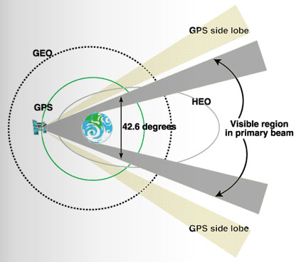
Realizing these benefits is not a trivial task. While the navigation signals broadcast by GPS satellites are well suited for orbit and attitude determination at lower altitudes, acquiring and using these signals at geostationary (GEO) and highly elliptical orbits (HEOs) is much more difficult. This situation is illustrated in FIGURE 1.
Figure 1. GPS signal reception at GEO and HEO orbital altitudes.
The light blue trace shows the GPS orbit at approximately 12,550 miles (20,200 kilometers) altitude. GPS satellites were designed to provide navigation signals to terrestrial users — because of this, the antenna array points directly toward the Earth. GEO and HEO orbits, however, are well above the operational GPS constellation, making signal reception at these altitudes more challenging. The nominal beamwidth of a Block II/IIA GPS satellite antenna array is approximately 42.6 degrees. At GEO and HEO altitudes, the Earth blocks most of these primary beam transmissions, leaving only a narrow region of nominal signal visibility near the limb of the Earth.This region is highlighted in gray.
If GPS receivers at GEO and HEO orbits were designed to use these higher power signals only, precise orbit determination would not be practical. Fortunately, the GPS satellite antenna array also produces side-lobe signals at much lower power levels. The National Aeronautics and Space Administration (NASA) has designed and tested the Navigator, a new GPS receiver that can acquire and track these weaker signals, dramatically increasing signal visibility at these altitudes.
While using much weaker signals is a fundamental requirement for a high orbital altitude GPS receiver, it is certainly not the only challenge. Other unique characteristics of this application must also be considered. For example, position dilution of precision (PDOP) figures are much higher at GEO and HEO altitudes because visible GPS satellites are concentrated in a much smaller region with respect to the spacecraft antenna. These poor PDOP values contribute considerable error to the point-position solutions calculated by the spacecraft GPS receiver.
Extreme Conditions. Finally, spacecraft GPS receivers must be designed to withstand a variety of extreme environmental conditions. Variations in acceleration between launch and booster separation are extreme. Temperature gradients in the space environment are also severe. Furthermore, radiation effects are a major concern — spaceborne GPS receivers should be designed with radiation-hardened parts to minimize damage caused by continuous exposure to low-energy radiation as well as damage and operational upsets from high-energy particles. Perhaps most importantly, we typically cannot repair or modify a spaceborne GPS receiver after launch. Great care must be taken to ensure all performance characteristics are analyzed before liftoff.
Motivation
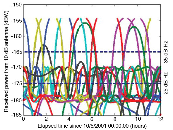
As mentioned earlier, for a GPS receiver to autonomously navigate at altitudes above the GPS constellation, its acquisition algorithm must be sensitive enough to pick up signals far below that of the standard space receiver. This concept is illustrated in FIGURE 2. The colored traces represent individual GPS satellite signals. The topmost dotted line represents the typical threshold of traditional receivers. It is evident that such a receiver would only be able to track a couple of the strong, main-lobe signals at any given time, and would have outages that can span several hours.
The lower dashed line represents the design sensitivity of the Navigator receiver. The 10 dB reduction allows Navigator to acquire and track the much weaker side-lobe signals. These side lobes augment the main lobes when available, and almost completely eliminate any GPS signal outages. This improved sensitivity is made possible by the specialized acquisition engine built into Navigator’s hardware.
Figure 2. Simulated received power at GEO orbital altitude.
Acquisition Engine
Signal acquisition is the first, and possibly most difficult, step in the GPS signal processing procedure. The acquisition task requires a search across a three-dimensional parameter space that spans the unknown time delay, Doppler shift, and the GPS satellite pseudorandom noise codes. In space applications, this search space can be extremely large, unless knowledge of the receiver’s position, velocity, current time, and the location of the desired GPS satellite are available beforehand.
Serial Search. The standard approach to this problem is to partition the unknown Doppler-delay space into a sufficiently fine grid and perform a brute force search over all possible grid points. Traditional receivers use a handful of tracking correlators to serially perform this search. Without sufficient information up front, this process can take 10–20 minutes in a low Earth orbit (LEO), or even terrestrial applications, and much longer in high-altitude space applications. This delay is due to the exceptionally large search space the receiver must hunt through and the inefficiency of serial search techniques.
Acquisition speed is relevant to the weak signal GPS problem, because acquiring weak signals requires the processing of long data records. As it turns out, using serial search methods (without prior knowledge) for weak signal acquisition results in prohibitively long acquisition times.
Many newer receivers have added specialized fast-acquisition capability. Some employ a large array of parallel correlators; others use a 32- to 128-point fast Fourier transform (FFT) method to efficiently resolve the frequency dimension. These methods can significantly reduce acquisition time. Another use of the FFT in GPS acquisition can be seen in FFT-correlator-based block-processing methods, which offer dramatically increased acquisition performance by searching the entire time-delay dimension at once. These methods are popular in software receivers, but because of their complexity, are not generally used in hardware receivers.
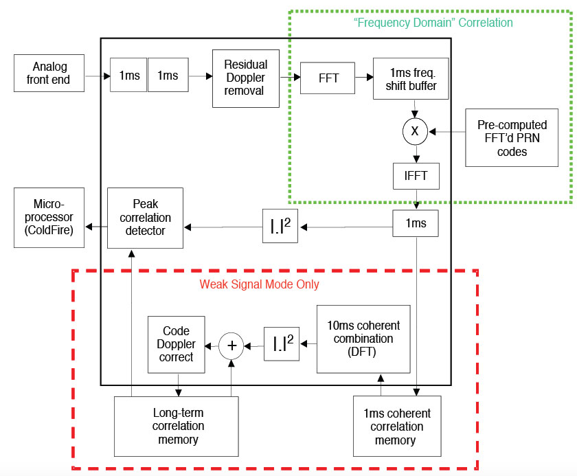
Exceptional Navigator. One exception is the Navigator receiver. It uses a highly specialized hardware acquisition engine designed around an FFT correlator. This engine can be thought of as more than 300,000 correlators working in parallel to search the entire Doppler-delay space for any given satellite. The module operates in two distinct modes: strong signal mode and weak signal mode. Strong signal mode processes a 1 millisecond data record and can acquire all signals above –160 dBW in just a few seconds. Weak signal mode has the ability to process arbitrarily long data records to acquire signals down to and below –175 dBW. At this level, 0.3 seconds of data are sufficient to reliably acquire a signal.
Additionally, because the strong, main-lobe, signals do not require the same sensitivity as the side-lobe signals, Navigator can vary the length of the data records, adjusting its sensitivity on the fly. Using essentially standard phase-lock-loop/delay-lock-loop tracking methods, Navigator is able to track signals down to approximately –175 dBW. When this tracking loop is combined with the acquisition engine, the result is the desired 10 dB sensitivity improvement over traditional receivers. FIGURE 3 illustrates Navigator’s acquisition engine.
Powered by this design, Navigator is able to rapidly acquire all GPS satellites in view, even with no prior information. In low Earth orbit, Navigator typically acquires all in-view satellites within one second, and has a position solution as soon as it has finished decoding the ephemeris from the incoming signal. In a GEO orbit, acquisition time is still typically under a minute.
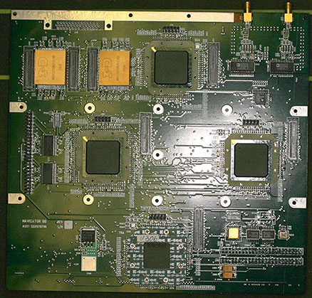
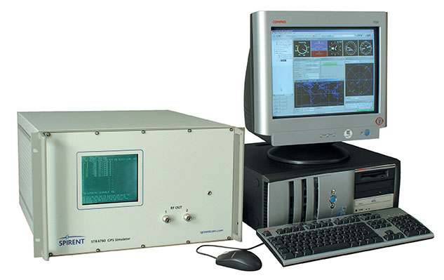
Figure 3. Navigator signal acquisition engine.Navigator breadboard.GPS constellation simulator.
Navigator Hardware
Outside this unique acquisition module, Navigator employs the traditional receiver architecture: a bank of hardware tracking correlators attached to an embedded microprocessor. Navigator’s GPS signal-processing hardware, including both the tracking correlators and the acquisition module, is implemented in radiation-hardened field programmable gate arrays (FPGAs). The use of FPGAs, rather than an application-specific integrated circuit, allows for rapid customization for the unique requirements of upcoming missions. For example, when the L2 civil signal is implemented in Navigator, it will only require an FPGA code change, not a board redesign.
The current Navigator breadboard—which, during operation, is mounted to a NASA-developed CPU card—is shown in the accompanying photo. The flight version employs a single card design and, as of the writing of this article, is in the board-layout phase. Flight-ready cards will be delivered in October 2006.
Integrated Navigation Filter
Even with its acquisition engine and increased sensitivity, Navigator isn’t always able to acquire the four satellites needed for a point solution at GEO altitudes and above. To overcome this, the GPS Enhanced Onboard Navigation System (GEONS) has been integrated into the receiver software. GEONS is a powerful extended Kalman filter with a small package size, ideal for flight-software integration. This filter makes use of its internal orbital dynamics model in conjunction with incoming measurements to generate a smooth solution, even if fewer than four GPS satellites are in view.
The GEONS filter combines its high-fidelity orbital dynamics model with the incoming measurements to produce a smoother solution than the standard GPS point solution. Also, GEONS is able to generate state estimates with any number of visible satellites, and can provide state estimation even during complete GPS coverage outages.
Hardware Test Setup
We used an external, high-fidelity orbit propagator to generate a two-day GEO trajectory, which we then used as input for the Spirent STR4760 GPS simulator. This equipment, shown in the accompanying photo, combines the receiver’s true state with its current knowledge of the simulated GPS constellation to generate the appropriate radio frequency (RF) signals as they would appear to the receiver’s antenna. Since there is no physical antenna, the Spirent SimGEN software package provides the capability to model one.
The Navigator receiver begins from a cold start, with no advance knowledge of its position, the position of the GPS satellites, or the current time. Despite this lack of information, Navigator typically acquires its first satellites within a minute, and often has its first position solution within a few minutes, depending on the number of GPS satellites in view. Once a position solution has been generated, the receiver initializes the GEONS navigation filter and provides it with measurements on a regular, user-defined basis. The Navigator point solution is output through a high-speed data acquisition card, and the GEONS state estimates, covariance, and measurement residuals are exported through a serial connection for use in data analysis and post-processing.
We configured the GPS simulator to model the receiving antenna as a hemispherical antenna with a 135-degree field-of-view and 4 dB of received gain, though this antenna would not be optimal for the GEO case. Assuming a nadir-pointing antenna, all GPS signals are received within a 40-degree angle with respect to the bore sight. Furthermore, no signals arrive from between 0 and 23 degrees elevation angle because the Earth obstructs this range. An optimal GEO antenna (possibly a high-gain array) would push all of the gain into the feasible elevation angles for signal reception, which would greatly improve signal visibility for Navigator (a traditional receiver would still not see the side lobes). Nonetheless, the following results provide an important baseline and demonstrate that a high-gain antenna, which would increase size and cost of the receiver, may not be necessary with Navigator. The GPS satellite transmitter gain patterns were set to model the Block II/IIA L1 reference gain pattern.
Simulation Results
To validate the receiver designs, we ran several tests using the configuration described above. The following section describes the results from a subset of these tests.
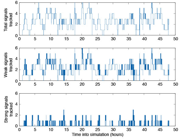
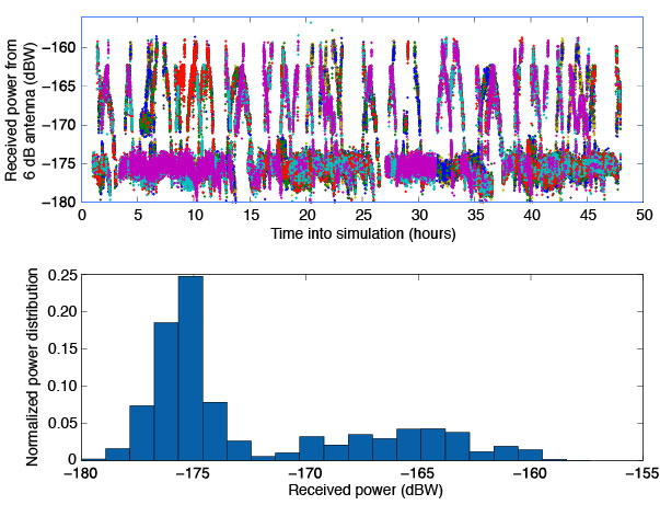
Tracked Satellites. The top plot of FIGURE 4 illustrates the total number of satellites tracked by the Navigator receiver during a two-day run with the hemispherical antenna. On average, Navigator tracked between three and four satellites over the simulation period, but at times as many as six and as few as zero were tracked. The middle pane depicts the number of weak signals tracked—signals with received carrier-to-noise-density ratio of 30 dB-Hz or less. The bottom panel shows how many satellites a typical space receiver would pick up. It is evident that Navigator can track two to three times as many satellites at GEO as a typical receiver, but that most of these signals are weak.
Figure 4. Number of satellites tracked in GEO simulation.
Acquisition Thresholds. The received power of the signals tracked with the hemispherical antenna is plotted in the top half of FIGURE 5. The lowest power level recorded was approximately –178 dBW, 3 dBW below the design goal. (Note the difference in scale from Figure 1, which assumed an additional 6 dB of antenna gain.) The bottom half of Figure 5 shows a histogram of the tracked signals. It is clear that most of the signals tracked by Navigator had received power levels around –175 dBW, or 10 dBW weaker than a traditional receiver’s acquisition threshold.
Figure 5. Signal tracking data from GEO simulation.
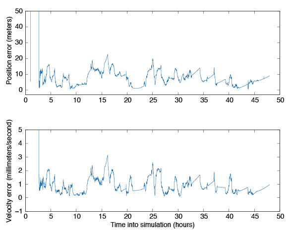
Navigation Filter. To validate the integration of the GEONS software, we compared its estimated states to the true states over the two-day period. These results are plotted in FIGURE 6. For this simulation, we assumed that GPS satellite clock and ephemeris errors could be corrected by applying NASA’s Global Differential GPS System corrections, and errors caused by the ionosphere could be removed by masking signals that passed close to the Earth’s limb. The truth environment consisted of a 70X70 degree-and-order gravity model and sun-and-moon gravitational effects, as well as drag and solar-radiation pressure forces. GEONS internally modeled a 10X10 gravity field, solar and lunar gravitational forces, and estimated corrections to drag and solar-radiation pressure parameters. (Note that drag is not a significant error source at these altitudes.) Though the receiver produces pseudorange, carrier-phase, and Doppler measurements, only the pseudorange measurement is being processed in GEONS.
Figure 6. GEONS state estimation errors for GEO simulation.
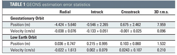
The results, compiled in TABLE 1, show that the 3D root mean square (r.m.s.) of the position error was less than 10 meters after the filter converges. The velocity estimation agreed very well with the truth, exhibiting less than 1 millimeter per second of three-dimensional error. Navigator can provide excellent GPS navigation data at low Earth orbit as well, with the added benefit of near instantaneous cold-start signal acquisition. For completeness, the low Earth orbit results are included in Table 1.
Navigator’s Future
Navigator’s unique features have attracted the attention of several NASA projects. In 2007, Navigator is scheduled to launch onboard the Space Shuttle as part of the Hubble Space Telescope Servicing Mission 4: Relative Navigation Sensor (RNS) experiment. Additionally, the Navigator/GEONS technology is being considered as a critical navigational instrument on the new Geostationary Operational Environmental Satellites (GOES-R).
In another project, the Navigator receiver is being mated with the Intersatellite Ranging and Alarm System (IRAS) as a candidate absolute/relative state sensor for the Magnetospheric Multi-Scale Mission (MMS). This mission will transition between several high-altitude highly elliptical orbits that stretch well beyond GEO. Initial investigations and simulations using the Spirent simulator have shown that Navigator/GEONS can easily meet the mission’s positioning requirements, where other receivers would certainly fail.
Conclusion
NASA’s Goddard Space Flight Center has conducted extensive test and evaluation of the Navigator GPS receiver and GEONS orbit determination filter. Test results, including data from RF signal simulation, indicate the receiver has been designed properly to autonomously calculate precise orbital information at altitudes of GEO and beyond. This is a remarkable accomplishment, given the weak GPS satellite signals observed at these altitudes. The GEONS filter is able to use the measurements provided by the Navigator receiver to calculate precise orbits to within 10 meters 3D r.m.s. Actual flight test data from future missions including the Space Shuttle RNS experiment will provide further performance characteristics of this equipment, from which its suitability for higher orbit missions such as GOES-R and MMS can be confirmed.
Manufacturers
The Navigator receiver was designed by the NASA Goddard Space Flight Center Components and Hardware Systems Branch (Code 596) with support from various contractors. The 12-channel STR4760 RF GPS signal simulator was manufactured by Spirent Communications (www.spirentcom.com).
FURTHER READING
1. Navigator GPS receiver
“Navigator GPS Receiver for Fast Acquisition and Weak Signal Tracking Space Applications” by L. Winternitz, M. Moreau, G. Boegner, and S. Sirotzky, in Proceedings of ION GNSS 2004, the 17th International Technical Meeting of the Satellite Division of The Institute of Navigation, Long Beach, California, September 21–24, 2004, pp. 1013-1026.
“Real-Time Geostationary Orbit Determination Using the Navigator GPS Receiver” by W. Bamford, L. Winternitz, and M. Moreau in Proceedings of NASA 2005 Flight Mechanics Symposium, Greenbelt, Maryland, October 18–20, 2005 (in press). A pre-publication version of the paper is available online at http://www.emergentspace.com/pubs/Final_GEO_copy.pdf.
1. GPS on high-altitude spacecraft
“The View from Above: GPS on High Altitude Spacecraft” by T.D. Powell in GPS World, Vol. 10, No. 10, October 1999, pp. 54–64.
“Autonomous Navigation Improvements for High-Earth Orbiters Using GPS” by A. Long, D. Kelbel, T. Lee, J. Garrison, and J.R. Carpenter, paper no. MS00/13 in Proceedings of the 15th International Symposium on Spaceflight Dynamics, Toulouse, June 26–30, 2000. Available online at http://geons.gsfc.nasa.giv/library_docs/ISSFDHEO2.pdf.
1. GPS for spacecraft formation flying
“Autonomous Relative Navigation for Formation-Flying Satellites Using GPS” by C. Gramling, J.R. Carpenter, A. Long, D. Kelbel, and T. Lee, paper MS00/18 in Proceedings of the 15th International Symposium on Spaceflight Dynamics, Toulouse, June 26–30, 2000. Available online at http://geons.gsfc.nasa.giv/library_docs/ISSFDrelnavfinal.pdf.
“Formation Flight in Space: Distributed Spacecraft Systems Develop New GPS Capabilities” by J. Leitner, F. Bauer, D. Folta, M. Moreau, R. Carpenter, and J. How in GPS World, Vol. 13, No. 2, February 2002, pp. 22–31.
1. Fourier transform techniques in GPS receiver design
“Block Acquisition of Weak GPS Signals in a Software Receiver” by M.L. Psiaki in Proceedings of ION GPS 2001, the 14th International Technical Meeting of the Satellite Division of The Institute of Navigation, Salt Lake City, Utah, September 11–14, 2001, pp. 2838–2850.
1. Testing GPS receivers before flight
“Pre-Flight Testing of Spaceborne GPS Receivers Using a GPS Constellation Simulator” by S. Kizhner, E. Davis, and R. Alonso in Proceedings of ION GPS-99, the 12th International Technical Meeting of the Satellite Division of The Institute of Navigation, Nashville, Tennessee, September 14–17, 1999, pp. 2313–2323.
BILL BAMFORD is an aerospace engineer for Emergent Space Technology, Inc., in Greenbelt, Maryland. He earned a Ph.D. from the University of Texas at Austin in 2004, where he worked on precise formation flying using GPS as the primary navigation sensor. As an Emergent employee, he has worked on the development of the Navigator receiver and helped support and advance the NASA Goddard Space Flight Center’s Formation Flying Testbed. He can be reached at [email protected].
LUKE WINTERNITZ is an electrical engineer in hardware components and systems at NASA’s Goddard Space Flight Center in Greenbelt, Maryland. He has worked at Goddard for three years primarily in the development of GPS receiver technology. He received bachelor’s degrees in electrical engineering and mathematics from the University of Maryland, College Park, in 2001 and is a part-time graduate student there pursuing a Ph.D. He can be reached at [email protected].
CURTIS HAY served as an officer in the United States Air Force for eight years in a variety of GPS-related assignments. He conducted antijam GPS R&D for precision weapons and managed the GPS Accuracy Improvement Initiative for the control segment. After separating from active duty, he served as the lead GPS systems engineer for OnStar. He is now a systems engineer for Spirent Federal Systems in Yorba Linda, California, a supplier of high-performance GPS test equipment. He can be reached at [email protected].