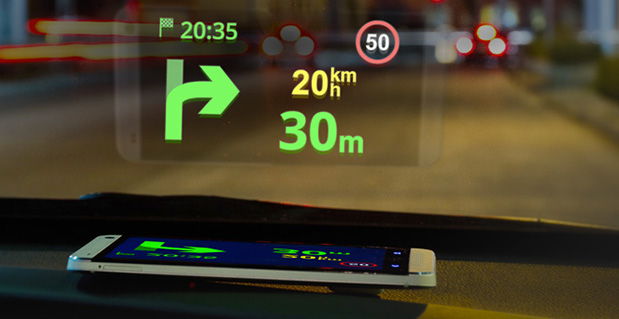
Sygic has announced a new product to make driving safer. Sygic’s Heads-up-Display (HUD) product projects navigation information onto drivers’ windshields, so they never have to take their eyes off the road to look down at their navigation software.
The product comes at a critical time for the holiday travel and shopping season, which is one of the most auto accident-heavy periods of the year. Sygic’s HUD is available as an in-app purchase for $4.99 and doesn’t need an expensive add-on product, as the projection can be emitted right from the Sygic GPS Navigation app on any iOS and Android phone or tablet.
Using Sygic’s HUD interface is straightforward. Drivers activate the feature from the app’s navigation menu, flip the screen via pop-up menu, and place their phone on their dashboard. The specially optimized interface will then
reflect clearly on the car’s windshield, displaying navigation information without the need for any expensive accessories. Sygic’s HUD feature gives them the full Sygic experience, complete with features like live traffic and turn-by-turn voice guidance.
“As we head into the heavy travel season, we hope our HUD will help drivers stay safe on the roads so they can spend more time with their family and friends and less time driving down heavily-trafficked and dangerous winter road conditions,” said Sygic CEO Michal Štencl.
Features of Sygic GPS Navigation include:
• Offline maps that don’t require a cellular data connection
• Turn-by-turn voice-guided GPS navigation
• 3D cities and landscapes
• Voice guidance in more than 40 languages
• Multi-stop routes and Drag & Drop route editing
• Speed limit display and audio warning
• SOS/Help to find assistance nearby
• Interactive map – tap on any street, POI, or photo to choose action
• Robust integration with third party
services like Groupon and TripAdvisor to find
things like deals, restaurants, hotels, attractions and more
• New speed cameras feature with a
constantly-updated database of stationary and mobile speed traps
Unlike other map services, data in Sygic: GPS
Navigation is stored on the user’s phone instead
of streamed from the Internet, which means that
Sygic users don’t have to worry about running up
against their cellular data caps by using GPS
navigation or getting lost in an area with poor
cell reception. When Sygic’s users are online,
they now have access to other helpful features
like real-time traffic and road incident sharing with other drivers.
Sygic GPS Navigation, now upgraded to version
13.3, is available in the iOS App Store and
Google Play, while the HUD feature can be
purchased from within the app for $4.99.
– See more at:
http://www.gisuser.com/content/view/31596/2/#sthash.goudUtyE.dpuf
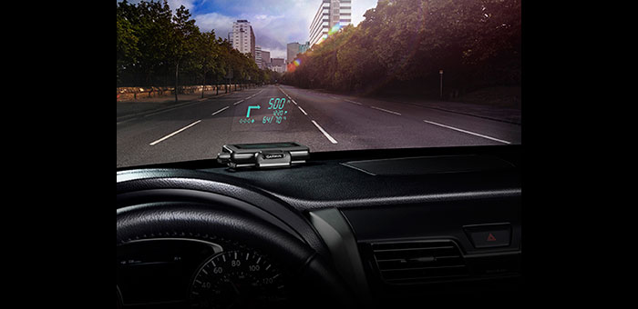
Garmin International Inc. has announced HUD, the company’s first portable head-up display for smartphone navigation apps. With the HUD display, drivers can view navigation directions projected onto a transparent film on the windshield or an attached reflector lens. Garmin said by providing comprehensive road guidance at a glance and right within the driver’s line of sight, HUD can help increase safety and reduce driver distraction.
HUD receives navigation information from a Bluetooth-enabled smartphone running a Garmin StreetPilot or NAVIGON app.
“Head-up displays currently have their place in select high-end cars, but HUD makes this technology available as an aftermarket accessory for any vehicle, at an affordable price,” said Dan Bartel, Garmin vice president of worldwide sales. HUD has an MSRP of $129.99. Garmin StreetPilot and NAVIGON apps, starting at $29.99 for a regional map (NAVIGON U.S. Central, East or West), provide premium turn-by-turn navigation for smartphones, including onboard maps, lane guidance, speed limit warnings, real-time traffic, and other features.
HUD offers more navigation details than other portable head-up displays, yet presents them in a simplified way that doesn’t divert the driver’s attention from the road, Garmin said. The directions are easy to follow and allow drivers to navigate even the most challenging interchanges and traffic situations with ease. HUD displays turn arrows, distance to the next turn, current speed and speed limit, as well as estimated time of arrival. It even lets drivers know what lane to be in for the next maneuver and alerts them when they exceed the speed limit, the company said. HUD also warns users of potential traffic delays and upcoming safety camera locations. The crisp display automatically adjusts the brightness level so projections are clearly visible in direct sunlight or at night.
Complementing the visual display, spoken turn-by-turn directions are provided simultaneously by a compatible Garmin or Navigon app, either through the smartphone speaker or a Bluetooth-connected car stereo. Music streamed to the car stereo from the smartphone will automatically fade out for turn-by-turn voice prompts. HUD also continues to display navigation information while taking incoming calls.
Users can choose between displaying HUD navigation information on their windshield, with the included, transparent film, or on to the included reflector lens that attaches directly to HUD. The device pairs wirelessly with a compatible Bluetooth-enabled iPhone, Android phone or Windows Phone 8. An integrated USB port on the vehicle power/adapter cable makes it easy to charge the smartphone while driving, Garmin said.
A virtual reference station network covering a metropolitan area supplies position corrections to commuter buses equipped with a driver-assist system to enable safe operation, even under harsh weather conditions, along high-volume roadways.
By Craig Shankwitz
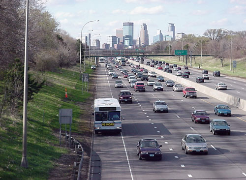
Bus-only shoulders on major traffic arteries enable a bus to travel on typically unused road right-of-way, bypassing congestion during peak rush hours. As the shoulder is typically only centimeters wider than the bus itself, lane-keeping becomes a key factor, and is accomplished in a pilot Minnesota project using dual-frequency, carrier-phase differential GPS (DGPS) as its primary positioning technology. DGPS provides position estimates accurate to 5–8 centimeters at a rate of 10 Hz, and is used to determine vehicle position and heading. An on-board map database is used to determine the position, orientation, and trajectory of the vehicle relative to the roadway.
Use of the shoulder as a busway offers several construction and operational advantages:
Ease of Implementation. The shoulder exists; there is no need to acquire and develop additional right of way.
Low Costs. The cost to strengthen and modify an existing road shoulder is significantly less than constructing a new busway.
Routing. Because bus-only shoulders follow existing routes, no changes to bus routes, bus stops, or transit stations are needed to support bus-only shoulder operations.
Customer Satisfaction. Transit customers who travel on buses that use a bus-only shoulder perceive a travel-time saving two to three times greater than actually realized. Keeping the bus moving at all times offers a significant psychological advantage.
Increased Ridership. A 1997 study of bus-only shoulders in the Twin Cities analyzed more than nine bus-only shoulder routes for two years and found a 9.2-percent increase in ridership along these routes. At the same time, total ridership had decreased by 6.5 percent.
However, the use of bus-only shoulders imposes additional stress and strain on a driver. The narrow bus-only shoulder leaves a driver very little margin of error. Operating within this small margin is difficult even during the best traffic and weather conditions, and degrades to nearly impossible during heavy traffic and poor weather conditions, which are frequent during Minnesota’s notoriously hard winters.
During difficult weather and traffic conditions, the use of the bus-only shoulder offers its greatest transit advantage. If a driver is unable to utilize the bus-only shoulder, this advantage is lost. A properly designed and executed driver-assist system (DAS) enables a driver to use the shoulder under all conditions, thereby increasing schedule adherence and, as a result, rider satisfaction.
Under the U.S. Department of Transportation’s Urban Partnership Agreement, the University of Minnesota’s Intelligent Vehicles Lab (IV Lab) and HumanFIRST program, the Minnesota Valley Transit Authority (MVTA), and Schmitty and Sons Transportation will soon deploy DAS on 10 Gillig low-floor transit buses. These buses will provide express service between Apple Valley and downtown Minneapolis, a 22-mile, one-way trip.
Driver-Assist History
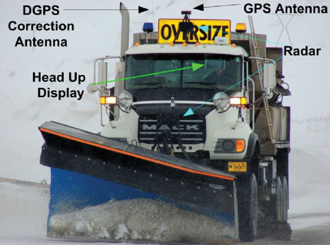
The IV Lab has developed and deployed DGPS-based DAS since 1995. The first deployment on public roads occurred in 2001, as part of the DOT’s Intelligent Vehicle Initiative Generation Zero Field Operational Test. The DGPS-based lane-keeping assistance was integrated with forward-looking radar for collision avoidance, enabling safe vehicle operation in zero-visibility conditions.
Two separate deployments took place in Alaska. The first occurred in 2003 with a snowplow and a snowblower which clear the Thompson Pass on the Richardson Highway. These vehicles are still in use. Because of this success, the State of Alaska installed the DAS in two more vehicles at Deadhorse Airport.
During the summer of 2010, the two original Thompson Pass systems will be upgraded with new computational hardware, and three new systems will be installed on three new highway maintenance vehicles. The value of the driver-assist system has been proven, and those who use it have grown to rely on its all-weather capabilities. It has functioned reliably for seven years in extremely harsh conditions.
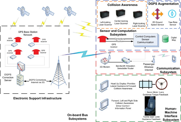
The DAS provides two primary capabilities for transit applications: lane-keeping and collision awareness. The system provides assistance only; a driver is always responsible for control of the vehicle. Figure 1 shows the components comprising the DAS.
Figure 1. Complete driver assist system component schematic, showing both infrastructure-based and vehicle-based components.
DGPS-Based Lane-Keeping. The primary positioning sensor used aboard the buses is a dual-frequency, carrier-phase GNSS receiver, providing centimeter-accurate position measurements at 10 Hz. With the exception of the DGPS augmentation system described later, all other DAS system processes are synchronized with the arrival of DGPS position updates.
Realtime CMR+ DGPS corrections are provided over the 3G cellular network from the IV Lab VRS network. The IV Lab VRS network is based on six receivers located around the perimeter of the Twin Cities Metro area. These six receivers are connected via landlines to a server system located in the IV Lab at the University of Minnesota, running GPSnet and RTKnet applications. To ensure GPS correction reliability, an integrity manager software issues alerts for both short-term and long-term aberrations in the data provided by the six base stations. This ensures accurate corrections are sent to the buses using the narrow shoulders.
The onboard receiver also plays a crucial role in accurately estimating vehicle body heading. In rural applications where GPS augmentation is unnecessary, GPS velocity heading estimates provided directly from a GPS receiver serve as a sufficiently accurate body-heading estimate. However, in GPS-denied environments where an augmentation system is needed to provide accurate position and heading estimates when GPS is lost, velocity heading from an onboard receiver is an insufficiently accurate estimate of vehicle heading. To support such navigation, the IV Lab developed a technique, described later, by which body heading can be estimated with errors less than 0.1 degree.
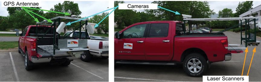
IV Lab mapping rig installed in a pickup truck: three dual-frequency, carrier-phase DGPS receivers; two laser scanners, one measuring retroreflectivity, the other road crown and rutting; and forward and sideview cameras, to help analyze anomalous data.
Map Databases
Lane-keeping uses DGPS with an onboard map database describing the location and type of lane boundaries and other relevant roadway elements to an accuracy of approximately 10 centimeters. These map databases can be constructed in one of three ways:
from sufficiently accurate photogrammetric data,
by driving centerlines and using known road-construction standards to d
etermine the location of lane boundaries and other relevant elements relative to the lane centerline, or
by using a combination of laser scanners, DGPS receivers, and cameras to determine the global location of the reflective markings that bound lanes and shoulders.
Lane-keeping information is continuously provided to the driver; lane-departure alerts and warnings use a comparison of vehicle speed and heading to the map database to determine when alerts and warnings should be issued.
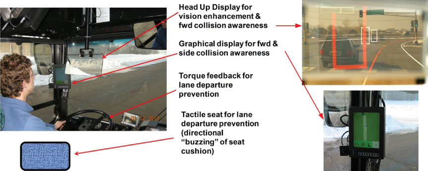
The alerts and warnings are provided via a multi-modal human-machine interface (HMI), illustrated in Figure 2, through three modes:
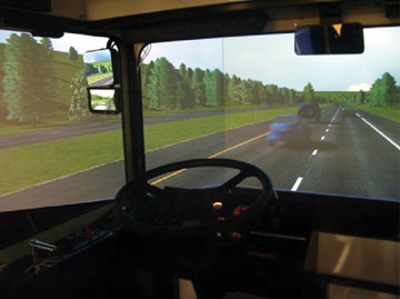
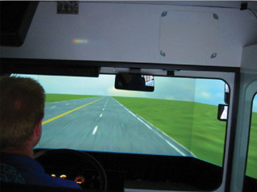
graphically, through a head-up display (HUD) that gives a virtual view out the windshield when environmental conditions limit visibility;
haptically, through a torque-actuated steering wheel giving a restorative torque on the steering wheel in the event of lane drift; and
tactically, through a seat equipped with actuators that vibrate on the side of the seat to which the lane is being departed.
Figure 2. Multi-modal driver interfaces. Left: Graphical, haptic, and tactile feedback modes provided to the driver. Upper right: View through the head-up display. Graphical lane departure alert indicated by left shoulder boundary colored red, collision awareness alert (white rectangles), and collision awareness warning (red rectangle). Lower right: Forward, left, and right side collision awareness information presented on the display on the left “A” pillar.
Lane-departure warnings come in stages. As the vehicle-trajectory estimator determines that the likelihood of a lane departure is sufficiently high, a lane-departure warning is issued to the driver through the HUD: a change in lane boundary color from white or yellow to red. Should the driver contact the lane boundary, a seat-based warning is activated; the side of the seat corresponding to the direction of lane departure vibrates, warning the driver. If the driver fails to respond to these two stimuli and continues past the lane boundary, the steering motor torque is applied. This multi-stage approach captures the drivers’ attention, but if they respond in a timely fashion, their annoyance is limited.
The torque applied by the steering servo motor is limited, and cannot deliver sufficient control action to autonomously steer the vehicle. This is by design; the driver is responsible for operating the bus. The level of torque applied to the steering wheel is analogous to an automotive front-end misalignment; it is sufficient to capture the drivers’ attention, but not to steer a bus off the road.
Forward-Collision Awareness. Sensing for forward-collision assistance is provided by a front bumper-mounted multi-plane scanning LIDAR sensor. Forward-collision alert and warning information is provided in two stages to the driver through the HUD. As now configured, if the obstacle detected is in the present shoulder of travel, the obstacle is represented as a red, open rectangle, with red indicating a warning status. If an object is located in an adjacent lane, the obstacle is represented as a white, open rectangle, with white indicating an alert status.
Obstacle-detection processing is enhanced by the presence of the onboard map database used for lane-keeping. Obstacle target information provided by the LIDAR sensor includes range, range rate, and azimuth angle to the target. The bus position and heading is provided by either DGPS or the DGPS augmentation system. Through a coordinate transformation, LIDAR information in the vehicle coordinate frame is transferred to the global coordinate frame. This allows the LIDAR target to be placed on the map database; if the target is in the vehicle lane of travel, it can be considered a threat, but if the LIDAR target is not in the same lane as the bus, then at that time the target is not a threat to the driver.
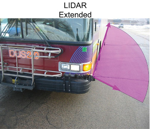
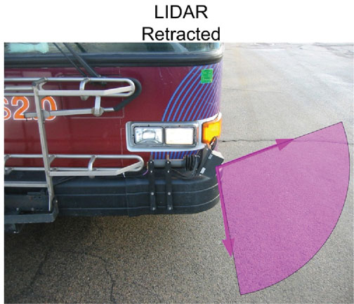
Side-Collision Awareness. Side collision awareness is enhanced by multi-plane LIDAR scanners mounted on on the front bumpers on both the left and right sides of the bus, and connected to a pneumatic actuator.
Side-collision awareness information is provided to the driver via an LCD panel mounted on the left front A-Pillar (see Figure 2). This display is touch-sensitive, and can be used by the driver to log in (only certified, trained drivers can operate the system) to select feedback modalities (choose any or all of the available feedback modes) and to check system status.
SIDE-MOUNTED LASER SCANNER used for both side-collision awareness and DGPS augmentation. When extended, the LIDAR scans 100 degrees of the horizontal plane. One boundary of the scanned plane points behind and runs alongside the bus; the other boundary points forward of the bus by approximately 10 degrees.SIDE-MOUNTED LASER SCANNER used for both side-collision awareness and DGPS augmentation. When retracted (right), the LIDAR points in the direction of the ground, and can be used for curb-following when DGPS is unavailable.
Suburban and Urban
Although the rural implementation of the DAS operates in extremely harsh weather conditions, these implementations are technically less problematic than suburban and urban implementations. In rural applications such as the snowplows, DAS-equipped vehicles typically operate with a single occupant in a small geographic area, travel on relatively low traffic-volume roads, and enjoy a clear view of the sky. Suburban and urban applications carry passengers, operate across a wider geographic area, travel on high-volume roads, and suffer from periods where view of GPS satellites is either partially or completely blocked.
These operational differences require substantial changes to the DAS subsystems for urban/suburban use.
DGPS Base Stations. In rural areas, DAS-equipped vehicles typically operate over a relatively small geographic area; a single GPS base station will provide adequate coverage as the maximum baseline between rover and the base station remains less than 25 miles. Suburban applications cover a much wider area, and a network of DGPS correction stations is needed to keep baselines low.
For the UPA project, the IV Lab operates a six-station virtual reference station (VRS) network. This network covers the greater Twin Cities Metropolitan area, and supplies compact measurement record (CMR) corrections to each DAS-equipped bus. Satellite observables are sent from each base station receiver to both the VRS server at the IV Lab and to a VRS server at the Minnesota Department of Transportation.
Broadcast of DGPS Corrections. In rural areas, the DAS system has served to keep roads passable in inclement weather conditions. This has been viewed as a safety application, and as such either UHF or VHF channels in the public safety bands have been used to broadcast DGPS corrections. In urban areas, no single UHF or VHF frequency is available to cover an entire metropolitan area. Therefore 3G cellular data communications are used to provide DGPS corrections to DAS-equipped vehicles.
Use of 3G cellular data communications brings the transit customer an added benefit: free Wi-Fi. The provision of DGPS corrections, using the CMR+ correction format, requires approximately 10 Kbit/second. This bandwidth is assigned high priority by the onboard router. The remaining 700 Kbit/s of 3G bandwidth is made available, at a lower priority, to bus passengers. On an express route service, passengers can e-mail and surf the web on their daily commute, making productive use of
time that might otherwise be lost.
The VRS server provides a unique correction to each DAS-equipped bus. Communication between the bus and the VRS server is initiated by the bus when it sends its coarse (uncorrected) position to the server. The server replies with a correction optimized for that coarse location. Corrections are sent at one-second intervals. Every two minutes, the bus sends its current position, and the VRS server responds with corrections optimized for that new location. With this scheme, the baseline between the VRS and the roving bus is never more than two miles. The two-mile limit maintains position accuracy without consuming excessive wireless or computational bandwidth.
DGPS Redundancy. In rural applications, the view of the sky is generally unobstructed, and FCC licenses provide adequate effective radiated power from the DGPS base stations. This assurance of access to both satellite and corrections signals generally suffices to support uninterrupted vehicle positioning. Both base-station and onboard GPS hardware have proven to be robust and reliable. With these local operating conditions, public agencies have found no need to augment DGPS for rural applications.
Suburban and urban applications, however, require an augmentation system to support DAS operation when DGPS is unavailable due to outages caused by overpasses, overhead road signs, tree canopies, and so on. Passenger safety and the need to provide reliable schedule adherence require that positioning be provided even when DGPS is unavailable, by a vehicle-based DGPS augmentation system.
Vehicle-Based Augmentation
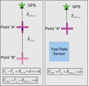
The vehicle-based augmentation system (VBAS) uses direct measurements of ground velocity, a measure of vehicle yaw rate, and an accurate estimate of the vehicle position and heading at the time DGPS is lost to estimate vehicle position and heading for the duration of signal loss.
A commercial off-the-shelf sensor designed for measuring vehicle and/or tire slip measures vehicle 2D velocity. Yaw rate can be measured either with an inertial rotational rate sensor or a second 2D velocity sensor. Yaw rate measured using a pair of these 2D sensors eliminates the rate bias and rate bias drift associated with inertial sensors. Figure 3 shows both configurations.
FIGURE 3 Two approaches to VBAS to mitigate DGPS outages. The diagram on left shows implementation with two 2D velocity sensors to determine vehicle yaw rate. Computationally, this is attractive as senor drift need not be considered. The diagram on the right shows an implementation with one yaw rate sensor, and one 2D velocity sensor. This is the configuration operating for the UPA; it requires yaw rate sensor drift compensation to provide accurate measures of vehicle yaw rate.
An accurate measure of vehicle heading at the time GPS positioning is lost is critical to the augmentation process. A performance goal of 20 centimeters tolerable error at the end of a 15-second outage for a vehicle traveling at 25 miles per hour (11.2 meters/second) requires a heading estimation error of no more than 0.07 degrees (that assumes the only source of error is attributable to the heading).
GPS outages (time from loss of position to reacquisition) attributed to passing under overpasses range from 7 seconds (single bridge) to 9 seconds (double bridge). The IV Lab augmentation system reliably provides sufficiently accurate position and heading estimates to carry through these outages. At the present level of performance, should an outage last more than 15 seconds, the accuracy of the augmentation system cannot be guaranteed. In this event, the driver is alerted, and the DAS is deactivated until a DGPS position fix is reacquired. Fortunately, since new receiver firmware was installed, no instances of an outage exceeding 15 seconds have occurred during two months of test, evaluation, and driver training.
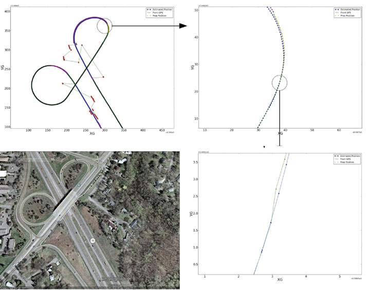
Figure 4 illustrates the accuracy of the VBAS system. At the time the fix solution is reacquired on the exit ramp, the lateral error between the fix solution and the position estimated by the VBAS is approximately 10 centimeters. This accuracy is sufficient to allow a driver to travel on the entrance ramp even during zero-visibility conditions.
Figure 4. Example of VBAS as a bus operates on the Cedar Avenue/Old Shakopee Road overpass. Bus trajectory is northbound on Cedar, exiting westbound Old Shakopee Road, then entering southbound Cedar Avenue from Old Shakopee Road. Upper left shows northbound trajectory and loss of satellite lock. Upper right shows reacquisition of DGPS, float, and fix states of the DGPS receiver. Lower right shows accuracy of VBAS system compared to DGPS when DGPS reacquires fix. Lateral error of VBAS at at the time the fix is reacquired is approximately 10 centimeters. Lower left shows satellite view of the interchange.
Driver Training
Bus-only shoulder operation has proven itself safe and, in fact, safer than normal transit operations, according to recent data. The goal of driver training is to prepare drivers to use the DAS system to enable them to safely use the bus-only shoulders in conditions under which they normally would not.
A rigorous training protocol developed in cooperation with the University of Minnesota HumanFIRST program, Schmitty and Sons Transportation driving instructors, and MVTA involves both simulator-based and on-road training.
Simulator-Based Training
Beefore using driver assist systems, bus drivers are continually taught that the driver controls the bus and is responsible for both the passengers and vehicle. Drivers take this responsibility seriously, and as such, develop skills and techniques that guarantee safe passage under all conditions, even when running on narrow, bus-only shoulders.
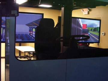
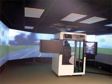
To best prepare drivers for using the DAS under difficult conditions, a high-fidelity driving simulator was commissioned. A DAS was installed in the simulator, and an interface to the simulator was created. In this context, a driver has the ability to train in normal and abnormal (low to zero visibility) conditions before beginning on-road DAS training and use.
In the simulator, the driver learns that the system only provides assistance; responsibility for the safety of the bus and passengers still resides with the driver. Experience with Alaskan snowplow operations, where formal training is limited to a few on-road test drives, has shown that a driver may take a few winter seasons to fully accept the system. This delayed acceptance is in part attributable to the fact that for six months per year a driver has no opportunity to train with the system. Acceptance gained over one winter season is lost during the summer.
The simulator installed at an MVTA bus garage uses a seat-based motion platform to achieve realistic vehicle dynamics. The DAS installed in the simulator allows a driver to train in all weather and traffic conditions on a geospecific roadway before transitioning to a DAS-equipped bus. Geospecificity is achieved through the creation of virtual worlds based on roadway data collected by the mapping vehicle shown earlier.
Bus-driving simulator at the MVTA bus garage in Burnsville, Minnesota.Bus-driving simulator at the MVTA bus garage in Burnsville, Minnesota.Bus-driving simulator at the MVTA bus garage in Burnsville, Minnesota.Bus-driving simulator at the MVTA bus garage in Burnsville, Minnesota.
On-Road Training
After a driver both demonstrates an
d acknowledges comfort and competence with the DAS in the simulator, training transitions to the actual route on which the buses will operate. Each of the 10 buses is equipped with a six-camera data-acquisition system. The six cameras capture not only the driver’s actions (hands, face, feet), but also views of the road (front, left, and right sides.)
Drivers travel with an instructor. The onboard data acquisition system can be used to reconstruct particular scenarios as a means to offer advice as to how the driver and system can better interact in difficult driving and traffic conditions.
On-road training benefits system developers as well. Training offers a driver an opportunity to test the system in real-time on an actual road. The perspective a driver brings is generally different than that of the developer, and the insights the end user provides typically produce a better system. As an example, driver experience with the system during the initial training period produced the staged approach to lane-departure alerts previously described.
Conclusion
The IV Lab, MVTA, and Schmitty and Sons Transportation will soon release 10 DAS-equipped buses into revenue service to support narrow bus-only shoulder service between downtown Minneapolis and Apple Valley, Minnesota. Although the IV Lab has deployed a number of DAS-equipped vehicles, this UPA deployment represents the first time that the system has been used to transport passengers. This deployment should prove that although DGPS systems are susceptible to periodic outages, a properly designed and executed augmentation system will provide a sufficiently robust system that will be accepted by both drivers and passengers. It will also demonstrate to other transit agencies that even narrow rights of way offer significant transit advantages at low cost, and that potential operational difficulties can be overcome through the use of DAS technologies.
Manufacturers
The buses carry Trimble R7 receivers and Ibeo Lux multi-plane scanning LIDAR sensors. The IV Lab VRS network is based on six Trimble NetR5 receivers. The server runs Trimble’s GPSnet and RTKnet applications, with the Trimble Integrity Manager.
Craig Shankwitz is the director of the Intelligent Vehicles Laboratory at the University of Minnesota.