Tag: IIHS

  • Testing autonomous vehicles inside and out

    Testing autonomous vehicles inside and out

    A test of Racelogic’s parking assistance system. (Photo: Racelogic)
    A test of Racelogic’s parking assistance system. (Photo: Racelogic)

    Racelogic helps vehicle manufacturers develop autonomous vehicle technology and test them on indoor test tracks and the open road.

    Racelogic helps vehicle manufacturers develop autonomous vehicle (AV) technology and testing houses test them. Over time, regulatory and consumer testing has evolved from indoor test tracks to outdoor open-road tests, and then to indoor controlled test environments.

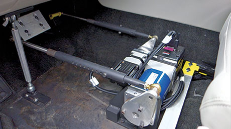
    “Due to their application, advanced driver-assistance systems (ADAS) originated and are still mainly developed and assessed on open-sky, controlled test tracks, tackling the most common killed and seriously injured (KSI) accident types,” said Wesley Hulshof, principal engineer – ADAS Testing at Racelogic. “These assessments usually make use of sophisticated driving robots for closed loop, centimeter-accurate path following and precise speed-controlled test-track assessments. The robots can only attain this accuracy by being fed the speed and positional data by GNSS sensors, such as the Racelogic VBOX.”

    Racelogic’s VBOX GNSS receiver. (Photo: Racelogic)
    Racelogic’s VBOX GNSS receiver. (Photo: Racelogic)

    Accuracy is key to conducting assessments for the European New Car Assessment Programme (Euro NCAP) and the U.S. National Highway Traffic Safety Administration (NHTSA). Using GNSS in conjunction with RTK base stations provides centimeter-level accuracy in position, said Hulshof, as well as accurate speed and heading information to measure ADAS data to both static and moving targets. Additionally, combining a GNSS receiver with an inertial measurement unit (IMU) allows for low-drift, high-accuracy speed and positioning information within areas of high GNSS multipath or temporary occlusions, such as gantries, bridges, forests or built-up areas.

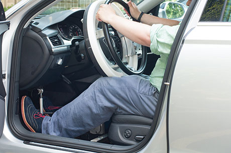
    However, “people do not just drive on closed test tracks with accurately positioned targets and infrastructure,” Hulshof said. “They do not drive at a constant throttle position and maintain an exact time-to-collision to the vehicle in front of them, like robots do. In fact, people often drive erratically.”

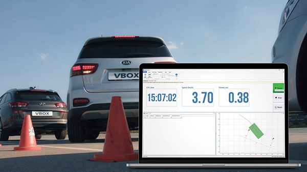
    For these reasons, testing houses are conducting supplementary assessments on the open road, under real-world conditions. In these conditions it is still important to know vehicles’ positions and speeds to localize them and validate the system’s sensors, networks and algorithms.


    Testing Stages

    Stage I: Controlled
    ADAS was developed for outdoor use because this is where car crashes occurred. For this, an open-sky GPS signal was essential for positioning. The types of tests and level of scientific rigor meant that the tests could be performed on closed test tracks.

    Stage II: Randomized
    Tests were brought to the open road to add elements not found within a closed environment such as traffic and higher speeds of the vehicle under test. For this, extra sensors were employed to add robustness in areas of obscured GNSS coverage.

    Stage III: Controlled
    Testing is brought back indoors for climate control and to assess L3/L4 AD functionalities such as valet parking.


    Because open-road testing does not permit being constantly within range of a static base station, Racelogic developed a moving base solution for open-road testing that gives accurate relative positioning between two or more vehicles.

    The increased demand for real-world testing of ADAS has generated demand for reliable ground truth data. “For example, if you consider a car driving on the winding roads of the Italian Alps and the position is out by 2m,” Hulshof said, “that is the difference between lovely scenery and falling off the side of a cliff. So, you need centimeter-level accuracy in the positional algorithms of the self-driving car, but also in the assessment tools, while we are testing it. For that reason, we still need GNSS and would ideally need RTK.”

    To meet this demand, Hulshof said, Racelogic produced its own networked transport of RTCM via Internet protocol (NTRIP) solution, consisting of a modem and associated service provider. It allows for global coverage of high-accuracy, absolute positioning of a test vehicle in open-road conditions. Both the NTRIP and the moving base solutions allow ADAS testing to centimeter-level accuracy on the open road without the need to be in radio range of an RTK base station, thereby greatly expanding the testing possibilities.

    “Whilst both the NTRIP and the moving base options allow for high-accuracy positioning,” Hulshof said, “they are still reliant on having an open sky for good GNSS coverage. IMU integration allows for improved accuracy over short periods of occlusion, but to truly give as accurate a signal as possible we need to be open to accept information from multiple satellite sources. That is why highest longevity accuracy is only achieved by using the GPS, GLONASS, Galileo and BeiDou constellations to provide the best RTK positioning performance in areas where that was not previously possible.”

    To control the environment and allow for year-round testing, test laboratories such as the Insurance Institute for Highway Safety (IIHS) facility in Arizona and Asta Zero in Sweden have purpose-built covered test facilities, giving shelter from extreme heat or cold. Testing inside both set-ups, however, still relies greatly on the test vehicle positioning. Standard positioning techniques via GNSS in these situations is simply not possible. Therefore, Hulshof said, Racelogic designed the VBOX Indoor Positioning System (VIPS), which allows for seamless testing indoors or outdoors. “Because this system works as an alternative to satellites, with the in-vehicle VBOX allowing RTK-level performance without GNSS, the test vehicle can travel from open-sky outdoor testing to a closed environment seamlessly, with no drop in data during the transition or afterward.”

    Finally, Hulshof said, ADAS and AD systems have moved on from straight-line highway scenarios to low speed turning scenarios often performed away from the open sky previously required for accurate GNSS coverage. Examples include multi-story parking garages and valet parking. “Scenarios such as self-parking and park-assist assessments, as well as indoor L1 ADAS, are becoming increasingly common requests by manufacturers on test facilities.”

    These environmentally controlled facilities can simulate real-life conditions that affect specific sensors — such as sensor flare, fog, mist and water films. These types of facilities use VIPS to give outdoor GNSS accuracy in an indoor controlled environment. “There is a trend toward bringing the testing from closed test track to randomized real world back into a highly contained, climate-controlled area,” Hulshof said. “We then have an option for anything.”

  • Robot: Target on Its Back

    Robot: Target on Its Back

    Photos: Brian J. Geiger.
    Photos: Brian J. Geiger.

    Two Autonomous Vehicles Seek Safe Avoidance in Critical Tests

    A new state-of-the-art research center runs car-makers’ safety systems through their paces, in tandem with a soft-target robot that can be crash-impacted without adverse effects. Precise positioning and exact repeatability of test sequences are key criteria.

    Paul Perrone, Perrone Robotics

    The Insurance Institute for Highway Safety has undertaken a $30 million expansion project at its Vehicle Research Center near Washington, D.C., enlarging and enhancing a state-of-the-art vehicle test track and building a new 700 x 300-foot (213 x 91-meter) covered track for weather-resistant testing.

    The VRC will use new robotic and positioning technologies to achieve required levels of precision and repeatability for vehicle testing of frontal collision avoidance and other safety systems. Tests of both the same and different vehicles must be conducted under  identical, controlled conditions for the results to have comparable fidelity.

    Crash tests and research conducted at the VRC help drive life-saving improvements in vehicle designs. The new facility will enable staff to evaluate emerging automated vehicle technology in commercial vehicle systems intended to prevent crashes or lessen their severity, with the goal of encouraging the entire industry to adopt the most effective new features.

    Safety systems in vehicles to be tested include the following:
    ◾    Adaptive cruise control
    ◾    Collision-imminent braking
    ◾    Lane-departure warning/correction
    ◾    Other automated technologies.

    Such functions represent semi-automated functions aboard vehicles now on the road. The system is also designed to address and test the full spectrum of semi- to fully-automated vehicles, addressing evolving levels of autonomy and ultimately producing driverless vehicle technology.

    IIHS has contracted Perrone Robotics, Inc. (PRI), to deliver a robotic system for testing such vehicles. PRI develops new applications using its MAX robotics and suite of automation software building blocks. MAX enables rapid integration of a range of sensor and actuator types and has evolved with several frameworks, including MAX-UGV for unmanned ground vehicles. PRI has used MAX-UGV to build automated passenger cars, all-terrain vehicles, tractors, custom platforms, and rockstar Neil Young’s long-range electric LincVolt, a converted 1959 Lincoln Continental.

    FIGURE 1. PRI test system.
    FIGURE 1. PRI test system.

    For the first phase of the IIHS project, the Perrone Robotics system includes a robot target vehicle with the footprint of a car, but measuring only 4 inches high, with a 1-inch ground clearance.

    A robot target vehicle with the footprint of a car measure 4 inches high.
    A robot target vehicle with the footprint of a car measure 4 inches high. Photos: Brian J. Geiger.

    Test Scenario Example. One instance to be tested is National Highway Traffic Safety Administration criteria for crash-imminent braking (CIB). The CIB concept goes beyond the forward-collision warning systems already found in many new cars by actually engaging the brakes when a driver, at fairly slow speeds, gets too close to the car in front of him. In tests, the while the test vehicle travels at similar speeds on a programmed collision course with the robot.

    The target robot vehicle carries one of a number of soft targets. If the vehicle under test fails to prevent a collision with the robot target, the test vehicle runs over the robot target vehicle, dislodging the soft target, but avoiding damage to the test vehicle, robot target vehicle, and the soft target. The next phase of the project adds smaller-footprint target robot platforms with soft targets, representative of pedestrians and cyclists.

    To ensure that the test vehicle can perform repeatable tests, the system also includes a drop-in actuator kit that can be installed into any test vehicle in 30 minutes or less. The system is designed to allow a human driver to sit comfortably in the vehicle and optionally drive, but can also control the throttle, brake, and steering to drive test profiles. Repeatability is key for the operation of robots and vehicles, as well as track conditions, which will be helped by the covered track.

    The VRC test track is installing Locata as its positioning system. In addition to alleviating concerns about GPS outages or dead/weak signal spots, this enables the PRI system to be operated reliably inside the new covered test track. While GPS is not an option for covered or indoor test sites and suffers from environmental issues, the high fidelity and localized positioning provided by Locata overcomes these barriers to test.

    Drop-in actuator kit steering.
    Drop-in actuator kit steering. Photos: Brian J. Geiger.
    Drop-in actuator kit throttle-brake.
    Drop-in actuator kit throttle-brake. Photos: Brian J. Geiger.

    PRI will deliver the target robot and drop-in actuators custom-built. The company looked at starting with existing platforms and building from them, but it would have been infeasible or overly expensive to meet the IIHS requirements for this system. Most existing systems were developed for vehicle dynamics testing or low-speed/simple collision testing. Most couldn’t handle some or all of the more challenging requirements such as the following:

    Drop-in actuator kit:

    • Allow human driver to sit comfortably and drive the vehicle without interfering;
    • Drive autonomously while also allowing for hybrid modes whereby test drivers and onboard systems may assist or take over controls;
    • Offer out-of-the-box programmability and flexibility to handle a wide range of test scenarios and automated vehicle levels;
    • Install into any vehicle in 30 minutes or less;
    • Do not damage vehicle with installation; retain a significant percent of resale value.

    Target robot vehicle:

    • Accelerate from 0 to 55 mph in 10 seconds;
    • Survive collisions at speeds up to 55 mph;
    • Allow collision-avoidance testing with minimal damage to test vehicles and target robot;
    • Scale for carrying a wide variety of soft-target payloads and enable a wide range of vehicles, from small car to SUV to tractor-trailer) to be tested.

    Locata positioning system:

    • Work outside and also on covered track; cover track area with no dead/weak spots;
    • Deliver better than 10-centimeter accuracy for position measurements and relative position control of robots and vehicles;
    • Deliver position updates at 100 Hz in combination with attitude and heading reference system (AHRS) or inertial navigation system (INS).

    The positioning requirement derives from the testers’ need not only for accurate location data of each vehicle, but for precise knowledge of how far apart they are while performing real-time control to orchestrate repeatable scenarios, intersecting vehicle and robot paths to determine whether the vehicle acts to prevent a collision.

    A human operator is easily accomodated within the drop-in actuator kit.
    A human operator is easily accomodated within the drop-in actuator kit. Photos: Brian J. Geiger.

    Safety Systems

    There is a driver in the test vehicle, and there are personnel present at the test site who could be injured by a test vehicle or target robot platform. In addition to wireless e-stop remotes, the test vehicle and target robot systems can be disabled and stopped by a number of events. In the target robot, an e-stop causes the battery pack to be completely disconnected from all vehicle systems, and a spring-load is released applying mechanical braking to stop the vehicle.

    Under normal conditions, the spring is held back with a pneumatic system and air is dumped upon e-stop event. A target robot e-stop is triggered by
    ◾    remote e-stop controller
    ◾    a command issued by control software
    ◾    loss of communication with external systems
    ◾    failure of or loss of communication with internal systems
    ◾    loss of power.

    Aside from fail-safe remote and onboard e-stop systems, additional safety measures are employed by means of safety controllers that monitor safety-critical regions of software, implement a wide range of robot-safety checking rules, and ensure that the robot is operating within safe parameters of the environment (such as by staying within an invisible fence and pre-defined operation boundary).

    Common MAX-UGV Robot Logic

    A common instrumentation and control system (CICS) for both the target robot platforms and test vehicle instrumentation and robotic assist platforms is illustrated in Figure 2.

    FIGURE 2. Target robot logic flow.
    FIGURE 2. Target robot logic flow.

    Embedded Controller. The heart and soul of the vehicle hosts and runs the algorithms, receives sensor data, and executes actuation commands to the motor controllers based on desired route plans and dynamic sensor information. This controller runs the MAX software platform, MAX-UGV framework, and various MAX drivers.

    I/O Controller. Handles inputs from sensors for temperatures, voltages, and currents as well as monitoring limit switches and actuating relays. Certain controls are planned such as mock brake lights on target robots and warning lights in test vehicles.

    Locata. A constellation of nine LocataLite units on towers covers the existing track for Phase I of the project. Phase 2 will require additional units to add coverage to the covered track; some towers will provide coverage to both tracks. Each target robot vehicle and each drop-in kit for the test vehicles carries a Locata rover.

    Locata’s new software essentially adds some capability from its indoor software to its outdoor software to deal with reflections/multipath issues caused by the metal buildings at the test site. The new software also allows the rover to perform real-time calculations on board, required for the less-than 10-cm accuracy. Previously this had to be done on a separate system and data had to be transferred back and forth, which worked against meeting real-time position update requirements for controlling speed, position, and relative position of robots and test vehicles. In test vehicles and target robots, the Locata rover position updates are merged with the output of an attitude, heading, and reference system (AHRS).

    AHRS. The CICS in the robots and test vehicles includes an AHRS that provides the required heading, position, and velocity updates. Accuracy requirements are heading, 1 degree; position, less than 10 centimeters; velocity, 1 mph. Our required position update rate is 10 Hz. We expect to achieve 100 Hz in our system, which improves self-nav capability and overall performance. This rate also applies to other measured/logged data. A Kalman filter computes data from sources within the AHRS and from external sources: GPS and Locata.

    Wireless Adapter, Antenna. On our critical channel, we exchange messages between vehicles to effect proper trajectory and relative positioning. Our e-stop controllers and safety systems also use this network. The non-critical channel is used for test setup and supervisory control, decimated data transmission for HMI monitoring, and logged data transmission.

    Wireless E-stop Interface. This interface is for remote shutdown of a vehicle. The e-stop triggers are similar for the test vehicle systems, but the driver can also disable the robotic system. Rather than brake the test vehicle, an e-stop of the test vehicle systems disables the steering, brake, and throttle actuators into limp-mode and releases control of the test vehicle to the driver.

    Safety Controller. A separate watchdog controller monitors live conditions and the embedded controller and onboard systems, and serves as a direct line for remote wireless e-stop.

    Electronics, Motors. These includes six high-performance 4-inch motors, motor controllers, cut-off contactors, and overall cut-off system for e-stop.

    Conclusion

    The IIHS expansion project is a first of its kind for automated vehicle testing, breaking new ground for target positioning and control, and providing the first indoor test track for this purpose. Data from these tests will be used to improve safety of on road semi- and fully-automated vehicles and help save many thousands of lives, setting a high bar for capability and performance of all automated vehicle functions. Requirements for safety, repeatability, and seamless handoff between driver and autonomous control of the test vehicles, as well as the speeds at which the robots must travel and survive collisions, pose significant challenges. We believe our systems meet them fully.