CSR plc today announced the launch of its SiRFusion Software Development Kit (SDK) for Android application developers. The solution enables indoor positioning for Android developers looking to create next-generation apps.
Developers can now leverage the SiRFusion library to rapidly integrate new location-based capabilities and services such as indoor location tagging and analytics for social networking applications, indoor navigation, lone worker efficiency and safety capabilities, as well as indoor asset tracking and targeted e-commerce services.
CSR is being acquired by Qualcomm, with the transaction expected to close by the end of the summer of 2015.
Mobile applications with integrated SiRFusion can now deliver the ubiquity of outdoor navigation to indoor environments without costly surveys or infrastructure upgrades. SiRFusion combines real-time Wi-Fi signals, satellite positioning information, pedestrian dead reckoning, and the company’s cloud-based CSR Positioning Center to calculate accurate indoor location. SiRFusion technology provides the accurate indoor position fixes needed to make continuous indoor navigation a part of everyday life. The system automatically crowd-sources a venue’s indoor Wi-Fi signatures as consumers walk through the location, and it has also been architected to accommodate future proximity and location technologies such as Bluetooth Smart beacons, Wi-Fi Round Trip Time (RTT), and Indoor Messaging System (IMES).
“Offering indoor positioning accurate enough to be useful has been a challenge that the industry has been trying to solve for many years,” said Anthony Murray, Senior Vice President, Business Group at CSR. “But with consumers coming to expect anytime-anywhere positioning wherever they are, our customers have continued to express a growing interest for accurate indoor positioning without the need for additional infrastructure. With our SiRFusion Software Development Kit, we have, for the first time, made indoor location a reality for developers who want to deliver innovative location-based products and services without proprietary infrastructure.”
SiRFusion for Android can be integrated into any app running on Android version 4.4 or later. The SDK will be available for download from www.csr.com in Q1 2015, and will include the SiRFusion library, API descriptions, and a Developer’s Guide. CSR will demonstrate SiRFusion for Android at the Location and Context World conference December 2-3, held at the JW Marriott in San Francisco, and at Consumer Electronics Show (CES) in Las Vegas January 6-9, 2015. To schedule a private briefing and demo at either event, contact [email protected]
In May 2011, Dinesh Manandhar and Hideyuki Torimoto of GNSS Technologies, Inc., Japan, penned a very interesting article in GPS World titled – Opening Up Indoors: Japan’s Indoor Messaging System, IMES. The opening paragraph of their lengthy article seemingly describes the Holy Grail for the indoor positioning lobby:
“An indoor messaging system (IMES) has been developed to meet the challenges of indoor and deep indoor positioning, as a system that can be implemented in any device that has a GPS/GNSS receiver without hardware modification. IMES can provide reliable 3D position data with a single transmitter device without performing range calculation[s].”
They go on to describe the IMES concept thusly:
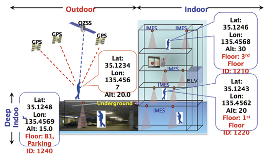
“The main concept of IMES is to transmit position and floor ID of the transmitter with the same RF signal as GPS. IMES transmits latitude, longitude, height, and floor ID by replacing the ephemeris and clock data in the navigation message of GPS. A single unit of IMES is enough to get the position data, since the position itself is directly transmitted.”
Now, you don’t have to be a rocket scientist to start thinking about interference and spoofing issues or risks, especially when you read that the navigation message ephemeris and clock data are being replaced by data broadcast by IMES. To be fair, the authors address these issues briefly:
“Since IMES shares the same frequency as [the] GPS L1 band (1575.42 MHz), there is an interference level that IMES may have on GPS signals. This interference has been studied in detail by conducting experiments and simulations. Based on these studies and analysis, various methods have been considered to avoid harmful interference to GPS signal. To avoid such interference, IMES center frequency is shifted by +/– 8.2 KHz from GPS L1 band. This will have the least impact on the GPS L1 band signal. For example, if the IMES signal is –110 dBm (very strong) and the GPS signal is –142 dBm (very weak), the loss of GPS signal (C/N0) due to IMES is less than 2 db. If the IMES signal is –120 dBm and the GPS signal is –142 dBm, there is no loss of GPS signal (C/N0). Based on this analysis, the IMES transmitter power must be controlled such that the maximum power to the receiver does not exceed –110 dBm at a distance of 3 meters from the transmitter. [There are] guideline[s] specified in the QZSS IS document for setting the transmitter effective isotropic radiated power (EIRP) based on location.”
Let’s put these concerns in perspective. I thoroughly enjoyed the article and firmly believe that we desperately need to solve the indoor positioning and navigation problems, especially for our warfighters and first responders. While many of today’s excellent commercial receivers work well indoors near windows and doors, they are absolutely abysmal underground and deep inside large buildings with lots of metal, or in the middle of dense urban canyons such as Tokyo, Japan. Without a doubt, there is a dire need for a system like IMES — or maybe exactly like IMES — but there must be some caveats and stipulations as to how the IMES system is implemented.
Not Alone
Fortunately, I am far from being a lone wolf in voicing my concerns and my position, for once again the conspiracy theorists as well as renowned scientist and policy makers are concerned about IMES and the operating systems they supposedly desire to replace or augment. Chief among them is the Father of GPS, Dr. Bradford Parkinson, who has frequently described improperly operated in-band pseudolites as “…just another name for a legal jammer or spoofer.” Having known Brad for almost 40 years, I am convinced few GPS experts in the world today have as much experience with pseudolites as Dr. Parkinson. Consequently, the very reason that an indoor navigation system such as IMES is needed may well be a portent for why it may well fail, unless it is implemented properly.
It would be easy but extremely tedious to write about the numerous issues facing IMES in a complicated and technical manner. Certainly previous articles have become bogged down in minutia, and I want to avoid that. It is actually very simple. The issues are fairly straightforward and should be faced head on and not hidden in the midst of tech-speak lingo, legal jargon, policy minutia or politics. So lets dive straight in, shall w,e and make sure these issues see the light of day?
Interference
There can be no doubt that IMES has the potential to significantly interfere with GPS and QZSS signals. The authors of the IMES article are quite clear concerning the potential for interference, and in their own way attempt to mitigate it with signal power restrictions. Their example of a small three- to four-story building with IMES transmitters may indeed be adequate for signal power mitigations, but what happens in Tokyo where tall buildings — skyscrapers if you will — abound? When the Tokyo Skytree skyscraper opened to the public in 2012, it was then listed as the world’s tallest tower and Japan’s biggest new landmark. At over 2,080 feet tall, this is definitely the type of building where one would need an IMES system. With an average of 20 IMES transmitters per floor and weighing in with over 200 floors, we can quickly see that there would be over 4,000 IMES transmitters in this one building alone, all broadcasting simultaneously on or near the center frequency for GPS. Absent stringent regulations and infinite care (the IMES article authors propose that the pseudolite network operator will have the responsibility to continuously monitor each pseudolite and the pseudolite network to prevent interference), and perhaps even with those caveats in place, the GPS L-band noise floor would be such that GPS signals would be incapable of being received.
Now, put 20 such buildings in a ten-block area and the noise floor would be almost incalculable and certainly not predictable. Dr. Parkinson’s fears are realized; your legalized IMES system becomes a distributed network of jammers and/or spoofers. However, technically IMES is currently far from being a legal jammer or spoofer as currently IMES transmitters are not legal to operate in the GPS band at 1559-1610 MHz under the International Telecommunications Union (ITU) Treaty per the International Table of Frequency Allocations of the ITU Radio Regulations. The ITU further states that IMES currently operates on an interfering basis with the co-primary allocations (ARNS/RNSS) in this band, and therefore are in violation of the ITU Treaty. However, Japan’s frequency regulatory agency can develop and implement regulations that allow IMES operations. When this occurs, if not operated within stringent guidelines, IMES could then be considered a legalized jammer or spoofer.
Even the Joint Research Centre of the European Commission, the JRC, states in its Executive Summary on pseudolites that in-band pseudolites pose a significant jamming risk to GNSS receivers. Specifically they state:
Pseudolites or pseudo-satellites are an emerging technology with the potential of enabling satellite navigation indoors. This technology found several applications that are not limited to indoor navigation. Precise landing, emergency services in difficult environments and precise positioning and machine control are few examples where pseudolite technology can be employed.
Despite the great potential of this technology, severe interference problems with existing GNSS services can arise. The problem can be particularly severe when considering non-participating receivers — legacy devices not designed for pseudolite signals. The design of pseudolite signals is thus a complex problem that has to account for market requirements (modifications of existing receivers for enabling the use of pseudolite signals, measurement accuracy, target application), regulatory aspects (frequency bands to be allocated for pseudolite services) and interference problems.
JRC investigates the main aspects to be considered for the design of a pseudolite signal standard minimizing the interference problem without compromising the location capabilities of the system. The focus is on the signal characteristics and topics relevant for the signal design.
Pseudolite or Communications System
The second technical portion of the interference issue revolves around how exactly you define IMES, for when you are dealing with radio regulation agencies semantics matter. Think back to the first paragraph of this article where the IMES authors defined IMES as a messaging system. That certainly sounds like a communications system to me, and others agree. Consequently, the question has been raised and rightfully so: Is IMES a navigation and positioning system, a pseudolite or a communications system? Honestly, to me it sounds like a bit of all three, but if you define it as a communications system, then Japan is seeking to authorize the integration of a communications system with known significant interference issues with GPS signals right in the middle — indeed, potentially on the center frequency of the protected navigation band using terrestrial PRN codes assigned by the U.S. government. If IMES is deemed an indoor pseudolite, then the interference issues are still there. But it is defined as a bonafide PNT system using authorized terrestrial PRN codes. Talk about a bucket of worms!
The issues here are numerous, and they need to be fully addressed to ensure that all those who are potentially affected clearly understand what is being proposed and the risk for the public at large, including who owns responsibility if something goes wrong. I could go on for several pages on this issue alone, but suffice it to say, we do not want to authorize a communications system that is a known and acknowledged GPS interferer right in the middle of the band — or anywhere in the band for that matter. Remember all the issues GPS had in the past several years with a communications system in adjacent bands. So, do we really want a known communications system — or communications system masquerading as a pseudolite, for that matter — with known GPS signal interference issues in the restricted GPS frequency spectrum? The blaringly obvious answer is absolutely not! Yet this is exactly what the IMES authors are proposing not only for Japan, but eventually, if they receive authorization, for other countries around the globe as well. Japan has twice petitioned the U.S. government to make the assigned IMES terrestrial PRN code allocations global in nature. Fortunately, to date those request have been denied.
Dichotomy
Certainly, other countries and companies have noticed this apparent frequency authorization dichotomy and are following suit. For instance the Conference of European Postal and Telecommunications agencies, or CEPT, which is Europe’s regional representative to the World Radiocommunication Conference (WRC), has proposed adding several troubling IMES-related agenda items for the quadrennial WRCs coming up in 2015 and 2019. Even more importantly, these critical issues could be aired in the next three weeks, as the agenda for the 2015 WRC will be largely set at a plenipotentiary conference happening October 20 through November 8 in Busan, South Korea.
There are what I consider to be dangerous proposals under consideration by the ITU (International Telecommunication Union), which should concern GNSS users worldwide. The ITU is the United Nations’ specialized agency for information and communication technologies — ICTs. This is the ITU, where every member state (currently 193) gets one vote, whether they fully understand the technical issues or not and regardless of whether they are a space-faring nation or have a dog in the fight, so to speak. This means that the vote of tiny Saint Lucia counts the same as the United States or Canada or Australia. The ITU charter is to “…allocate global radio spectrum and satellite orbits, develop the technical standards that ensure networks and technologies seamlessly interconnect, and strive to improve access to ICTs to underserved communities worldwide.” Fortunately, the ITU regulations, unlike the CEPT or IMES proposals, wisely require new transmitters proposing to operate in the radio navigation spectrum to operate without causing interference to primary users. Meanwhile, there are member states, countries and companies that want to capitalize on this seeming dichotomy within the global safety-of-life, historically protected, radio bands. Those nefarious efforts, for the future of GPS and GNSS worldwide, need to be stopped in their tracks.
Spectrum is a limited and valuable resource, to say the least, and here fortunately the ITU regulations have it right and do not risk human life, by intruding and potentially interfering with the frequencies used globally by airliners to control, route and land aircraft. I am convinced there are solutions available to us through cooperative efforts with the ITU and other national organizations that will produce pseudolites without causing interference in the protected safety-of-life frequency bands.
When Is a PRN Code Not a PRN Code?
Some of you who are a bit more savvy or have been following this fiasco for some time may now be thinking, what’s the problem, the IMES authors are merely using and proposing further use of U.S. government-authorized terrestrial PRN codes for IMES. This indeed touches on the third thorny issue, which is not only technical but political as well — the use of and authorization to use PRN codes for what is ostensibly a communications system, if you believe the authors of the IMES article, who go to great lengths to differentiate IMES from pseudolites. They continually make the argument that IMES is not a pseudolite, but as we shall soon see, when the U.S. government authorized these specific PRN codes (173-182) for Japan, they were to be used solely for a low-power terrestrial pseudolite program, not an in-band communications system.
Technically, these specific PRN codes assigned to the Japanese for IMES expire in 2017. The authorization of these PRN codes come with numerous restrictions that legally make the codes useful only for the Japanese landmass. This is where the technical, political and operational issues come to a head. We are in for some tough sledding here. However, I will endeavor to make it as simple as possible.
History
In 2007, ten PRN codes were specifically assigned to the Japan Aerospace Exploration Agency or JAXA “for the Indoor Messaging System (IMES) terrestrial pseudolites of the Quasi-Zenith Satellite System (QZSS).” The Memorandum of Agreement from the GPS Wing at SMC (Space and Missile Systems Center) in Los Angeles at Los Angeles Air Force Base (LAAFB) clearly states that the codes are valid for ten years and expire on 19 November 2017, unless a renewal application is filed and approved. Hence, PRN codes 173-182 for IMES were assigned with several crucial caveats and restrictions by the U.S. government that are definitely pertinent to our discussion:
The codes are designated for low-power terrestrial regional applications limited to Japan only.
Although the GPS Wing conducts an initial check on PRN number requests with respect to potential interference issues, the issuance of a PRN number does not convey authority to radiate in the [GPS] band. In order to radiate in the GPS L1 band, the applicant [Japan] shall obtain a frequency assignment from the [Japanese] national authority.
The GPS Wing assumes no responsibility for ensuring systems using these spreading codes follow domestic radio frequency regulations or other applicable laws or regulations, or for ensuring that systems using GPS PRN codes do not cause radio frequency interference.
GPS PRN codes were developed for signals transmitted from satellites, and are not necessarily optimized for use by terrestrial transmitters.
The maximum effective isotropic power for each terrestrial transmitter will be less than -94 dBW.
The QZSS [organization] is responsible for the redistribution of these spreading codes throughout Japan and will limit their use to Japan only.
With all these restrictions, it is difficult to see how the IMES authors could legally use, distribute or promote authorization of IMES and the use of the PRN codes outside of Japan and at the power levels related in the GPS World IMES article. Regardless of the IMES author’s interpretation of the PRN code assignment, the GPS Wing 2007 Memorandum restrictions and caveats are clear, and it cannot be disputed that the codes expire in 2017 unless renewed by the USAF. The PRN codes are restricted to the landmass of Japan even if they are renewed, and if IMES wishes to broadcast anywhere in the GPS band, they need to have permission from their national frequency allocation authority (the Ministry of Internal Affairs and Communications, which is equivalent to the U.S. FCC –Federal Communications Commission) to do so.
The Way Ahead
This is the easy part from my perspective. See if you don’t agree. If the U.S. government is concerned about IMES and what Japan is planning to do with the assigned PRN codes for terrestrial use, the U.S. government through the USAF has the options to:
Rescind the PRN codes immediately.
Insure the Japanese adhere to the caveats and restrictions in the original Memorandum.
Simply refuse to renew or recertify the codes for future use and/or recommend for IMES frequencies that are outside the protected GPS band.
Update and clarify the footnote on the GPS Wing PRN Codes website pertaining to the Japanese IMES PRN Codes with all the restrictions listed in the GPS Wing Memorandum so other countries will realize this is not a global IMES PRN assignment.
Japan is a valuable ally and we need to work together cooperatively, but frankly, the plans laid out for IMES by the authors in the GPS World article must be troubling to those whose job it is protect the GPS spectrum and enforce mutual agreements with our allies. If we were just concerned about a Japanese IMES system, this whole discussion might be moot. However, other countries and commercial companies around the world are watching closely and laying the groundwork for similar IMES and pseudolite incursions into the GPS L-band spectrum — if the Japanese are allowed to proceed and the limited use of PRN codes for IMES is not clarified for all. No one, and I include the Japanese, wants to see this happen if it means interference with GPS, and QZSS for that matter.
Fortunately, where European countries are concerned, there are the ITU regulations. Specifically for GPS and pseudolites, the CEPT regulation has a license condition that requires the pseudolite network operator to submit to the European country regulator confirmation of the terrestrial PRN codes from the GNSS operator before operating pseudolites in the GPS band. So again, the U.S. government wields the hammer here.
Therefore, the U.S. government must act immediately and decisively to put an end to the threats against the protected GPS spectrum caused by the proposed in-band IMES system. At the same time, the Japanese government has an obligation and responsibility to adhere to the letter of the law where the original GPS Wing 2007 IMES Memorandum is concerned.
Finally, the U.S. government must urgently engage cooperatively with the European Union administration and Japan to prevent the authorization and proliferation of interfering devices in the GNSS frequency bands, and to work together to ensure the positive benefits to GNSS from commercializing pseudolite uses outside the GNSS radio frequency bands. GNSS manufacturers worldwide are successfully marketing commercial pseudolites that do not cause interference. In my opinion, this is the way to go both in terms of regulations and governance.
Until next time, happy navigating, and remember GPS is brought to you free of charge by the United States Air Force.
By Dinesh Manandhar and Hideyuki Torimoto, GNSS Technologies, Inc. Japan
An indoor messaging system (IMES) has been developed to meet the challenges of indoor and deep indoor positioning, as a system that can be implemented in any device that has a GPS/GNSS receiver without hardware modification. IMES can provide reliable 3D position data with a single transmitter device without performing range calculation.
The cost of embedding location data in portable electronic devices is so low that universal penetration can be foreseen in the next five years. Roughly 70 percent of the world’s population now uses approximately five billion cell phones. This number has doubled in the last four years. Future growth is expected at the same or even a higher growth rate.
Due to the emergence of smart phones and location-based services (LBS), mobile phones are used not only for communications but also for many applications related to LBS, entertainment, and games. GPS/GNSS devices are included in mobile phones due to compulsory requirement of E911 and safety-and-rescue services by law in many countries for security and safety.
Access to map data and value-added services using these map data is getting cheaper and eventually will be freely available. Major service providers like Google, Nokia, and Apple already provide access free of cost, and they increasingly focus on location as a core business construct.
GPS/GNSS devices were designed to work outdoors, and most GNSS applications are limited to outdoor environments. However, GNSS reliability, availability, and accuracy have led to development of many new and innovative applications that are designed for use in both outdoors and indoors in a seamless fashion. Today, GNSS receivers are integrated in many other devices like mobile phones, navigation systems, personal navigation devices, game devices, security devices, and many LBS-related devices. These devices are increasingly used in indoor environments. Indeed, people generally spend much more time indoors than outdoors. Hence, it is extremely important to have a reliable system that can provide fairly accurate position data even in indoor and deep indoor locations.
Current GNSS systems do not provide solutions for indoor and deep indoor environment with reliable accuracy of 10–20 meters. New modernized signals such as L5 do provide better position accuracy and better signal reception in indoor areas, but achievable positioning will still vary, and will continue to require more than four visible satellites with some assist data — and still be limited to soft indoors environments such as rooms with glass windows or walls. Limitations remain for hard and deep indoor environments.
To surmount these obstacles and provide indoor navigation, various technologies such as pseudolites, assisted GPS, wireless networks (Wi-Fi), Bluetooth, RF tagging, and so on have been developed. However, these technologies have their own limitations and are not the most suitable tools for seamless positioning and navigation. Except for pseudolite and A-GPS, they are designed for communication, not for positioning or navigation purposes, but are used for navigation purposes since no other suitable technology exist.
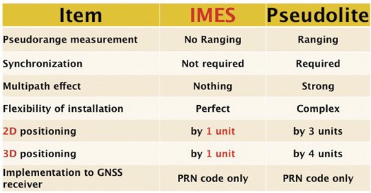
Pseudolite systems are currently in use for indoor positioning. While technically sound, a system needs at least four signal transmitting units. To cover a large area, it needs many transmitters suitably located and time-synchronized to one other, or their clock errors must be known. Pseudolite systems provide position data based on range calculation from the receiver to a number of transmitters, and this calculation is heavily affected by signal multipath. Table 1 compares IMES and pseudolites.
Table 1. Comparison between IMES and pseudolite.
A-GPS is widely used in mobile phones to compute position data. A-GPS technology includes high-sensitivity signal processing to acquire weak signals and external assistance of data like time, approximate position, and satellite-orbit related parameters. Provision of assistance data requires a communication link between the receiver and the data source, for example, the mobile phone network itself. Thus, A-GPS will not be possible if there is no communication link.
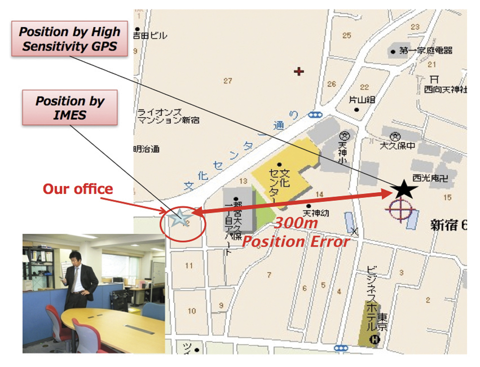
Normally, A-GPS provides 2D position data. The height data (if 3D output is available) will be highly erroneous. The accuracy of such position data varies from few tens of meters to few hundreds of meters. Also, the position data is heavily affected by signal multipath. Figure 2 compares IMES position and mobile phone position inside an office building. The A-GPS position error is about 300 meters in this case.
FIGURE 2. Indoor position from high-sensitivity GPS and IMES.
Wi-Fi is used for indoor positioning in many mobile phone devices. The phone provides position data from a built-in GPS receiver, a Wi-Fi device, cell ID, or a combination of any of these. Recently, position data from Wi-Fi has become popular for indoor as well as outdoor position, since Wi-Fi signals are so freely available. However, using these Wi-Fi signals requires registering the signal power and availability at reference locations. To do this, a huge number of Wi-Fi devices are registered driving around the city. Since these devices are basically installed for communication purposes, they can be relocated, removed, or new devices may be installed without any information to the users or service providers. Thus, continuous maintenance and updating of all these devices are necessary at certain time intervals. The coverage of Wi-Fi devices is not uniform and may vary widely from area to area, affecting position accuracy.
Telecom service providers are considering the possibilities of seamless positioning technologies. They would like to have one single device that can provide 3D position data both indoors and outdoors, without additional power or cost, and with satisfactory 3D position information. If such a seamless positioning technology is available, it will undoubtedly generate a huge global commercial market. The availability of such technology will also aid development of new applications in location-based services, advertising, marketing, entertainment, and gaming.
We have conducted research in indoor positioning for the past few years, beginning with pseudolite systems. We have developed IMES to meet the shortcomings of the technologies described earlier for indoor and deep indoor positioning. IMES for a seamless positioning environment can be implemented in any device that has a GPS/GNSS receiver, without hardware modification. IMES can provide satisfactory and reliable 3D position data with a single transmitter device without performing range calculation.
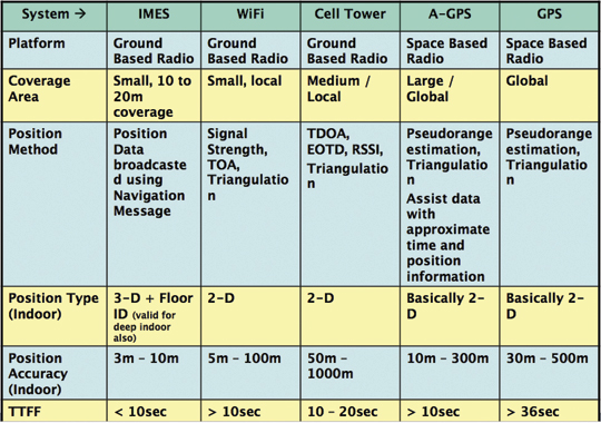
Table 2 compares IMES with other indoor-position capable devices. IMES can provide the same accuracy even in deep indoor locations, whereas cell tower, A-GPS, and GPS cannot work in such areas. All other systems except IMES provide only 2D position data indoors. The height data from A-GPS is very unreliable and hence cannot be used.
Table 2. Comparison of IMES with other indoor positioning systems.
IMES Concept
The main concept of IMES is to transmit position and floor ID of the transmitter with the same RF signal as GPS. IMES transmits latitude, longitude, height, and floor ID by replacing the ephemeris and clock data in the navigation mes
sage of GPS. A single unit of IMES is enough to get the position data, since the position itself is directly transmitted.
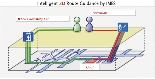
Figure 3 shows the concept of seamless position data using IMES, where the same receiver can be used both indoors and outdoors without interruption. GNSS satellites provide positioning and navigations outdoors, while IMES provides indoor navigation. Since the signal structures of GPS satellites and IMES is the same except for the navigation message contents, the same receiver can be used for both cases. Current GPS receivers will be capable of receiving IMES signals with modification of firmware only to decode the navigation message. Figure 3shows the concept of seamless 3D route guidance.
Figure 3. Seamless 3D route guidance using IMES.
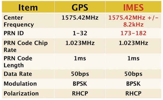
Signal Properties. The IMES signal is designed much like the GPS signal. It uses the same center frequency as GPS with an offset of +/– 8.2 kHz to minimize the possible interference from IMES to GPS signal. Ten PRN codes from 173 to 182 are assigned for IMES. These codes are provided by the U.S. government. Other signal-related parameters are the same as the GPS L1 C/A code signal. Table 3 shows IMES signal properties with respect to the GPS signal.
Table 3. IMES signal properties with respect to GPS.
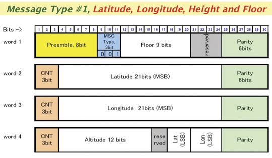
IMES has four different types of navigation message. The most significant is Type 1 as shown in Figure 4. It transmits latitude, longitude, height, and floor ID. The transmission of floor ID is a key factor for perfect 3D position data. Other message types are Type 0 (2-D position data with floor ID), Type 3 (short ID), and Type 4 (medium ID).
Figure 4. IMES Message type 1, 3D position, and floor
Interference Issue
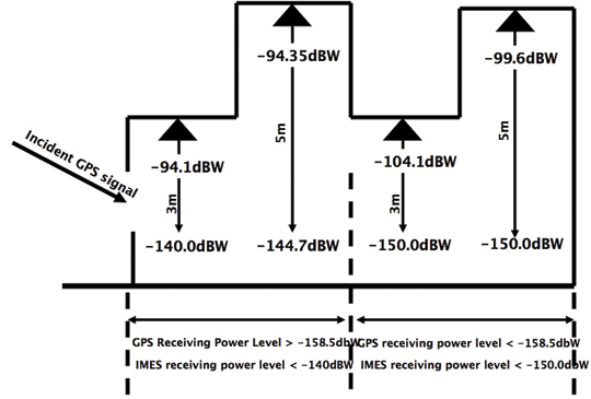
Since IMES shares the same frequency as GPS L1 band (1575.42 MHz), there is an interference level that IMES may have on GPS signals. This interference has been studied in detail by conducting experiments and simulations. Based on these studies and analysis, various methods have been considered to avoid harmful interference to GPS signal. To avoid such interference, IMES center frequency is shifted by +/– 8.2 Khz from GPS L1 band. This will have the least impact on the GPS L1 band signal. For example, if the IMES signal is –110 dBm (very strong) and the GPS signal is –142 dBm (very weak), the loss of GPS signal (C/N0) due to IMES is less than 2 dB. If the IMES signal is –120 dBm and the GPS signal is –142 dBm, there is no loss of GPS signal (C/N0). Based on this analysis, the IMES transmitter power must be controlled such that the maximum power to the receiver does not exceed –110 dBm at a distance of 3 meters from the transmitter. Figure 5 shows the guideline specified in the QZSS IS document for setting the transmitter effective isotropic radiated power (EIRP)based on location.
Figure 5. IMES transmitter power setup guideline in QZSS IS document.
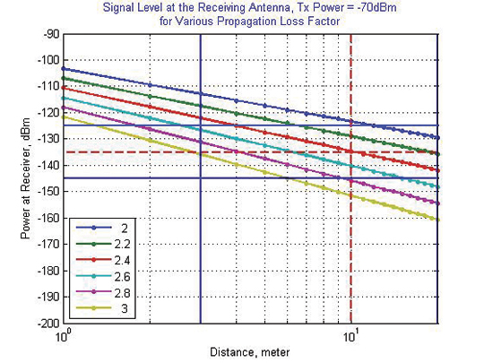
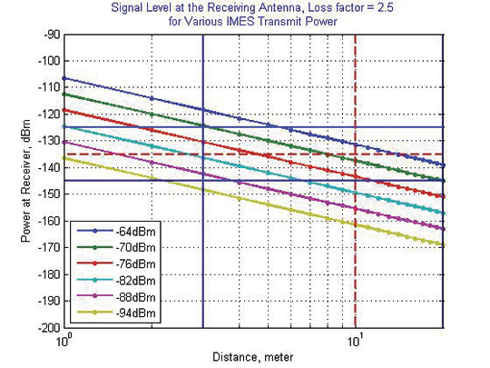
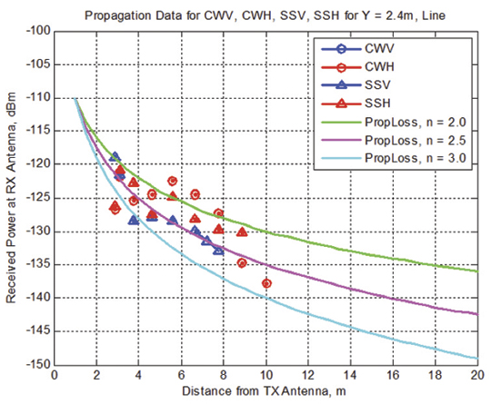
Figure 6 shows the signal propagation loss for transmitter power of –70 dBm for various propagation loss-factor values of n. Figure 7 shows path loss for various transmitter power for the same loss factor, n = 2.5. These graphs shows the maximum power that shall be used to cover an area without exceeding the maximum power level. If a single unit of IMES cannot cover the complete area, then multiple IMES units will be deployed to cover the entire area with suitable power level. These graphs serve as a guideline for setting transmitter power.
Figure 6. Signal path loss for –70 dBm signal for different path loss coefficient, n.Figure 7. Signal path loss for path loss coefficient, n = 2.5, for different transmitter power levels.
The signal propagation loss is calculated using the following equation; the gain of transmitter and receiver antennas is considered as unit gain (0 dB).
Hence, the equation depends on distance from the transmitter, d, and the propagation loss factor, n. The value of n is 2 for free space and increases for areas with objects that obstruct the signal. An office with soft partitions may use n = 2.5. The graphs can be used as a guideline to estimate the transmitter power to cover an area within the allowed power levels.
Application Areas
IMES can be used wherever indoor position data is required. It depends upon the application for that particular location as well. For example, an infrastructure-related safety application should have IMES installed at all elevators, escalators, staircases, emergency exits and routes, fire-fighting unit locations, and so on. Here are some of places where IMES might be used:
Every room of a building, to provide exact room location.
At entrances, exits, elevators, escalators, staircases, public facilities, and corridors for indoor navigation.
At every emergency exit for guidance.
Along hallways and lobbies at set intervals to guide the user.
In front of shops for advertising and information.
In sign posts to provide user’s location and guidance.
Complement other positioning systems like Wi-Fi, RF Tag, UWB, and so on.
As an indoor ground control point for surveying of large and multi-storey buildings.
With security cameras to provide accurate position data.
In factory production lines for automated control of moving objects.
Business Perspective
IMES technology was developed with the guiding concepts of low-cost global implementation and ease of installation and use. Low cost on the transmitter side is achieved by developing large-scale integratin (LSI) chips and IMES installation, setup, and database management tools. At the receiver side it is achieved by design of IMES signal so that existing GPS receivers in mobile phones, PDAs, or any other devices can use IMES by modifying only the firmware. The signal is designed so that it can adapt to other GNSS signals available in the future, for example, Galileo, QZSS, or Compass signals, requiring only firmware modification. Global implementation is made possible by signal design compatibility with existing GPS or GNSS signals. Ease of use is achieved again by signal design: one IMES transmitter can provide 3D position data, including floor information, with reliability and accuracy of a few meters even in deep indoor locations.
The development of IMES LSI chips (IMES transmitter) will also lead to development of value-added products for many consumer household appliances. For example, the green energy concept produced low-power LED lightbulbs. IMES chips can be installed in LED bulbs at very low additional cost. Similarly, it can be built in many other products like power socket devices, security devices, timing devices, and sensors where position data is also critical. This will provide an opportunity for the manufacturers to provide value-added products to users with indoor positioning devices. Not only electrical products but some construction materials or interior decoration materials like gypsum (dry
wall) boards can be made with built-in IMES chips. Installation of one piece of wallboard with an IMES built-in chip can provide position data in the room, reducing installation cost while not affecting the interior design of the room.
Implementation of IMES will also lead to new applications in the field of location-based services and applications where position data are necessary. It can also lead to new applications using IMES as an indoor electronic ground control point (GCP) in large buildings and indoor areas.
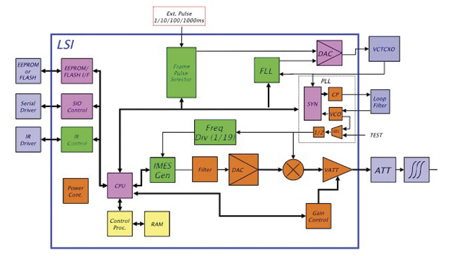
Chip Development. To reduce IMES transmitter cost, the IMES LSI chip has been developed and will be available by the end of the third quarter of 2011. This will reduce overall cost and size, and create platforms to develop value-added products integrating with other devices and systems. The chip is designed for global communications systems like personal handy-phone system (PHS, a mobile phone communication system developed in Japan), CDMA, and GSM. Figure 8 shows a block diagram of the chip transmitter.
The basic specifications of the LSI chip are: size, 12 x 12 millimeters; power, to be determined; maximum transmit power, –30 dBm or –60 dBm (user selectable); frequency, L1 band, 1575.4282 MHz or 1575.4118 MHz (user selectable); PRN codes, 173–182 (user selectable); signal type, GPS L1C/A, with upgrade capability to other GNSS signals.
Installation and Management
An IMES installation, setting, and management system has been developed to facilitate deployment. The main purpose of the system is to provide IMES transmitter position data (latitude, longitude, height) without conducting precision surveys, thus reducing installation, setting, and management costs. The system helps locate optimum locations for IMES transmitter siting, control transmitter EIRP power, set PRN IDs, and assign position data. The system can also use various types of map data sources to generate necessary floor data or indoor maps in 3D. The inputs can be either 3D vector data or 2D raster images, or even paper maps.
The overall system consists of four sub-systems:
IMES Setup Tool (ISET). This tool is used to set up the IMES transmitter. It provides two basic functions: to set up signal-related data (setting PRN code, transmitter power, navigation message rate, and so on) and to set up message-related data (position data, floor data, message types and their contents, message sequence, and so on). The R&D version of IMES also allows transmitting some special data for research and development purpose. It is possible to change the preamble value different from GPS, load a different PRN code table than IMES, change the navigation message data rate, generate a BOC(1,1) signal to test L1C-like signals, and change the RF frequency. The setup tool also has user-access management so that only authorized users can change certain sensitive data like PRN code, position data, and transmitter power.
IMES Database Management Tool (IDBM). This tool simplifies installation and management by providing a necessary database including a building-related database, a service-provider database, a device-related database, other integrated sensors database (if any), and a signal-related database. Since IMES is controlled and managed, guaranteed and authorized services can be provided for dedicated applications. This enhances the reliability of an IMES-based positioning system for infrastructure, security, and safety-related applications.
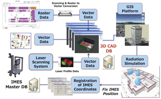
3D Mapping Tool (IMAP). This tool, shown in Figure 9, provides a 3D map database for IMES either for implementation or end-user applications. The mapping tool can use 3D vector data (for example, existing DXF files), raster image data, or direct user input. A laser scanning system with CCD camera is used to generate 3D data if existing data is not available. The tool creates walls, windows, doors, ceilings and other smaller objects from the laser data. If data are available in paper drawings, they are scanned to create raster images before digitizing them into vector format.
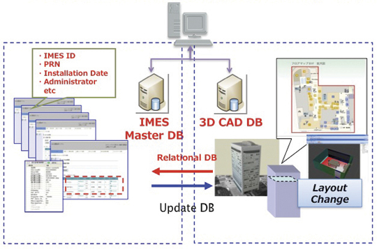
Figure 9. 3D Map Database Development System.Figure 10. Concept of IMES database for implementation, setting and management.
The system will ultimately create a 3D database of a building at floor level that can be linked with external databases. Figure 10 shows the overall concept of the IMES database system that includes both IMES database and 3D map database. The two database systems are linked by a relational database system. Any update in the map database can be reflected into the IMES database.
Signal Propagation Loss Tool (IPMODEL). This tool simulates the signal level where IMES will be set up. It is necessary to have optimum deployment of the transmitter to cover the area as large as possible within the allowed power level. Although the allowed maximum EIRP power level is –64 dBm for Japan, the approach is always to use the least power possible to cover the area, to avoid any possible harmful interference to other systems as well as to limit the availability of the signal to only the desired area.
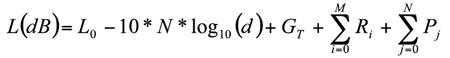
The following equation is used to calculate the signal path loss which is based on Frii’s free-space path-loss model.
GT is the transmitter antenna gain. The receiver antenna gain is assumed to have unit gain (0 dB) and hence not included in the model.
L0 is the power loss at 1 m distance and is given by 20 x log10(signal wavelength) — 20 x log10(4*pi).
N is the path-loss factor, which is 2 for free space, 2.5 for office room with soft partition, and 3.0 for rooms with hard partition.
Ri is loss due to i number of reflections by objects.
Pj is loss due to j number of penetrations through objects.
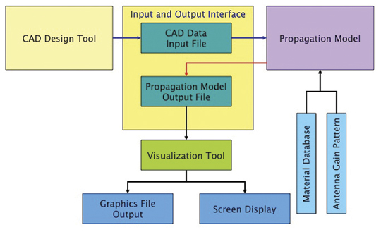
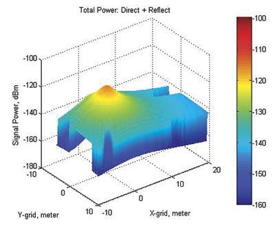
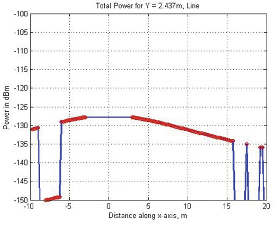
Figure 11 shows the propagation-loss tool flowchart. It uses 3D map database provided by the 3D mapping tool and database from the database management tool. It also uses antenna gain pattern and material electrical properties to compute the power loss due to reflection and penetration. Figure 12 shows the signal propagation output from the model for a building lobby. Figure 13 and Figure 14 show the output from the propagation loss results from the actual measurement and model output, respectively. The results match within a difference of few dBs.
Figure 11. Path Loss Tool flowchart.Figure 12. 3D view of signal power in a building lobby.Figure 13. Actual signal power measured at different locations in the lobby shown in Figure 12Figure 14. Signal power output from the propagation loss tool at the same location shown in Figure 13
Experiments and Demonstrations
Experiments and demonstrations have been conducted to validate the IMES concept, uses, and applications. Early experiments validated the
concept, message design, and interference analysis. Later experiments focused on actual implementation for infrastructure, and social-network and location-based applications. Pilot projects have been conducted in collaboration with the Japanese government to test IMES capabilities for seamless positioning and navigation and for social infrastructure platform.
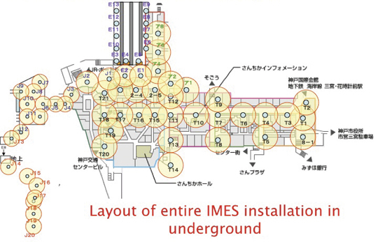
The Free Mobility Project in Kobe is the biggest social experiment using IMES for seamless navigation under the sponsorship by the Ministry of Land, Infrastructure, Transport, and Tourism. The project was conducted in an underground shopping mall of Kobe railway station. Shopping mall visitors were asked to participate in the navigation using IMES-capable mobile phones. Most visitors could follow the route they had chosen or find the destination point using the IMES set-up.
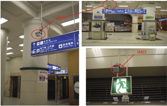
A total of 70 IMES transmitter units were installed at locations including ticket counters, elevator entrances, emergency exits, fire-extinguisher locations, staircases, station entrances, and alleys of the shopping mall. Figure 15 shows a part of the IMES transmitter location map. It covers one of the sections of the shopping mall. Figure 16 shows various locations where IMES transmitter devices were installed. As shown in Figure 17, intelligent 3D route guidance can be performed based on user preference. For example, a user in a wheelchair must be guided by a route that has no staircases, shown by green route in the figure, to reach the destination. A pedestrian can be guided by red route, which is the most direct route to the destination.
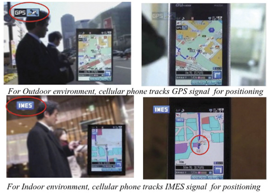
Figure 15. IMES transmitter location map to cover the underground shopping mall in Kobe Station.Figure 16. Installation of IMES near the station entrance and emergency exit.Figure 17. Intelligent 3D route guidance using IMES.Figure 18. Seamless navigation by mobile phone using GPS and IMES.
The distribution of each IMES transmitter is done in such a way that it covers a radial distance of 10 to 20 meters. The deployment density of IMES depends on the location environment. If an IMES device is located near the entrance, the coverage distance will be around 10 meters to minimize transmitted power. IMES devices in deep indoor locations can cover a radial distance of about 15 to 20 meters.
Commercially available mobile phones with a firmware update for IMES were used to receive the IMES position data. The phones also included the shopping mall and station map including related databases for various applications.
Conclusions
IMES can provide reliable and guaranteed 3D position accuracy, including floor information. IMES signal design is done in such a way that it can use existing as well future GPS/GNSS receivers without any hardware modifications. Necessary implementation, setup, and management tools are also developed to facilitate IMES installation and to minimize the cost so that large-scale global implementation is possible. IMES LSI chips are being developed for large-scale implementation. IMES will also help in developing many other location-based applications and services. IMES evaluation kits will soon be available for joint R&D projects.
IMES technology-related patents have been filed in Japan and many other countries. The basic patents have already been approved in Japan. GNSS Technologies invites academic institutions to participate in joint R&D projects.
Dinesh Manandhar is a visiting researcher at the University of Tokyo, where he received his Ph. D, and a senior researcher at GNSS Technologies Inc. He is one of the designers of IMES message structure and involved in developing indoor navigation system based on IMES for seamless navigation environment. He can be reached at [email protected].
Hideyuki Torimoto is the president of GNSS Technologies Inc. Japan. He established Trimble Navigation Japan and Weathernews Inc. in 1986. He also established the Research Forum on Social Infrastructure for Advanced Positioning (NPO) in 2003 and the Satellite Technology Laboratory in Tokyo University of Marine Science in 2004. He served as Satellite Division Member of ION for 2003-04. He can be reached at torimoto @ gnss.co.jp.