Fraunhofer IIS has opened paper submissions for The International Conference on Indoor Positioning and Indoor Navigation (IPIN) 2023, which takes place Sept. 25 -28 at the Nordostpark in Nuremberg, Germany.
The event is dedicated to indoor positioning, its applications and recent developments. The last decade has seen tremendous technical advances in indoor positioning. However, unlike the GNSS solutions established in the outdoor environment, there is not yet a technology that is affordable and accurate enough for the general market.
The potential applications of indoor localization are all-encompassing, from the home to vast public areas, from internet of things and personal devices, to monitoring applications.
The conference expects to attract up to 300 industrial and academic experts from the fields of computer science, electronics and surveying to address these challenges and the future of the industry.
To learn more about the conference and paper submissions, visit INIP-Confrence.org.
The latest software release for the SLAM-based NavVis M6 Indoor Mobile Mapping System (IMMS) automatically detects and removes point cloud artifacts, including moving objects in static scenes, the company said.
This image shows what an object looks like where the laser beam has hit an edge, before and after the algorithm has been applied. (Image: NavVis)
NavVis is a global provider of indoor spatial intelligence solutions. The latest IMMS release removes artifacts from point clouds during the post-processing of scan data.
Fringe points and dynamic objects are two common types of point cloud artifacts that affect all 3D laser scanning devices. Fringe points arise when a laser beam hits the edge of an object as well as its background. This scattered beam ultimately appears as a “fringe” around the edge of the object in the point cloud.
The second type of point cloud artifact results when dynamic objects, such as humans walking through a scan, are captured by the laser scanner and then appear as artifacts in the point cloud.
A point cloud before and after the algorithm has been applied to a dynamic object. (Image: NavVis)
According to the company, the NavVis M6 IMMS is a simultaneous localization and mapping (SLAM)-based system that uses laser scanners to capture a high volume of measurement points of an environment. As SLAM-based mobile mapping systems move through the environment while scanning it, objects are observed from multiple different angles and positions.
With the latest software update, the algorithms applied during the post-processing of scan data use those multiple observations to detect whether measurement points actually exist in the physical space. If it is determined that the point does not exist and is instead resulting from the laser beam hitting an edge or an object moving through the space, this point is automatically removed.
The result is a much cleaner, crisper point cloud that requires less clean up time in point cloud editing software and that is easier to use for applications such as BIM modeling, the company said.
“We have been working hard to develop a very precise SLAM technology that significantly improves the quality of point clouds captured by a mobile device,” said Georg Schroth, NavVis co-founder and CTO. “As this latest software feature shows, SLAM offers a lot of potential for laser scanning and AEC professionals who are looking for technology that not only speeds up the capture of data but also delivers high quality point clouds. We see a lot of potential in this technology and look forward to sharing future innovations.”
Mapping company NavVis has launched the M6, a next-generation indoor mobile-mapping system that the company says can overcome the scalability and data quality constraints of reality capture technology.
Surveyors and architecture, engineering and construction (AEC) professionals can now use reality-capture technology for large-scale indoor mapping projects. The M6 can be used for factory planning and creating and updating as-built BIM (building information modeling) models and construction monitoring.
The NavVis M6 is an all-in-one system that captures 360-degree immersive imagery, photorealistic point clouds, Bluetooth beacons, Wi-Fi signals and magnetic field data.
The NavVis M6 features a mobile lidar system that lets it scan up to 30 times faster than stationary devices, letting users capture up to 30,000 square meters in a day.
Cutting-edge 6D simultaneous localization and mapping (SLAM) technology significantly improves the quality of data captured. Thanks to 6D SLAM, M6 continuously scans even complex indoor environments, including uneven surfaces or changing elevations such as ramps, open spaces or long corridors without compromising the quality of the data.
M6’s innovative software is complemented by hardware features designed to improve the quality of data and ease of capture: four laser scanners with a range of up to 100 meters are arranged to maximize scan coverage, while six cameras automatically take high-resolution images during mapping. The innovative design of the M6 includes camera placement that keeps the operator in a blind spot.
NavVis IndoorViewer software gives stakeholders access to the scanned environment through an interactive virtual building in their browser.
“The NavVis M6 marks a quantum leap in indoor mobile mapping,” Felix Reinshagen, CEO of NavVis. “Anyone who needs to scan large properties, run repeated scans or would like to move into the field of reality capture will profit from the groundbreaking data quality.
“With M6, users can now quickly capture large, complex indoor environments for typical tasks such as updating floorplans, documenting construction progress or creating as-built BIM models. At the same time, M6 captures the data needed to provide customers with additional deliverables such as browser-based immersive walkthroughs and indoor navigation,” Reinshagen said.
Target is installing app-based indoor mapping in its stores, making it easier for customers to find what they’re looking for.
Following a 2015 test, the U.S. retail chain is integrating beacon and Bluetooth technology with its mobile app. The app will show the shopper’s location in real time as they move about the store (with a familiar blue dot), and display nearby sales and deals.
Shoppers will also be able to find an item on the map through their digital shopping list.
Target describes the new technology as “a GPS for your shopping cart.”
“Just click on an item from your list and the app will indicate on a store map the precise aisle where you can find your item,” said Target chief information and digital officer Mike McNamara.
The beacons are a function of new, energy-efficient LED lighting that Target is installing in its stores.
Another mobile enhancement is Target’s integration of its savings app Cartwheel within its main store app. (Cartwheel is more popular than the primary Target app.) Target will use the beacon technology to highlight which of its Cartwheel deals are near a shopper’s current location. In the months to come, the app will support mobile payments at checkout.
The new indoor location technology will be live in across half of the chain of 1,800 stores in time for the 2017 holiday season.
When it comes to renovating a building, unforeseen structural problems or lack of knowledge about the materials used can result in costly delays. Detailed site surveys help to highlight these issues before work begins — and digital technology is playing an increasingly important role in identifying them.
The GeoSLAM ZEB-REVO. (Image: GeoSLAM)
A project undertaken at a 112-year-old school highlights the advantages of using 3D mobile indoor mapping for rapid and simple site surveys.
“The beauty of scanning an historic building is that you find yourself delving into the stories behind its life,” said Stuart Cadge, sales and marketing coordinator at GeoSLAM. “As you peel back the layers you discover how the building has been used and altered over many decades of use.”
This was certainly the case at the Attucks school in Kansas City, Cadge said. The distinctive red-brick building was designed by local architect Charles A. Smith and built in 1905. It is known for its colonial revival influences and also played a key role in the educational history of the African-American community.
Two decades later, the school was suffering from over-crowding, and Smith was asked to extend it with a two-storey wing that connected to the east façade of the building. While the 1905 building had been symmetrical, the extension changed the floor plans considerably. Nevertheless, Smith delivered a sympathetic design that incorporated some of the original architectural details, ensuring the new wing was in keeping with the building’s aesthetic.
While details of the school’s building history are available on national and state registers, it would not have been possible to uncover problems in its structural condition without an accurate survey.
A Unique Challenge
Redeveloping and retrofitting a building like Attucks requires careful planning to uncover any existing conditions in its infrastructure. Civil engineering firm BHC RHODES was tasked with providing a 3D Revit building information model (BIM) of the building. The firm decided to use lidar 3D mobile mapping technology provided by GeoSLAM to achieve this.
The extremely rapid and efficient workflow of the GeoSLAM solution meant that possible setbacks in the project, caused by weakness in the structure, could be identified in advance, helping to speed up delivery time and reduce the overall project spend.
At Attucks, there were visible signs of deterioration to the wooden flooring, as well as concerns about ceiling collapses and air quality — specifically, asbestos.
The Value of Technology
“The process of mapping a historic building can expose site personnel to a number of risks, so BHC RHODES wanted to ensure they spent as little time on-site as possible,” Cadge explained.
As well as entering the Attucks building, personnel were required to move across the site safely, climb stairs and go into places that a trolley scanner could not.
On this basis, the firm chose the GeoSLAM ZEB-REVO, a handheld, lightweight, mobile mapping scanner, which employs 3D Simultaneous Localization And Mapping (SLAM) technology. In this case, it was seen as a much more time- and cost-effective alternative to terrestrial, static or trolley-based systems.
The complete 3D scan of the building comprises four separate scans and over 160 million data points. (Image: GeoSLAM)
“The ZEB-REVO is an incredibly useful tool for indoor mobile mapping, particularly in buildings with multiple storeys,” Cadge said. “It enables users to simply ‘walk and scan’ the building, in order to generate building footprints, 2D plans, area measurements for real estate and facility management, 3D BIM models — the list goes on.”
In the case of Attucks, just four-and-and-half hours were needed to scan the whole building, with the ZEB-REVO recording more than 43,000 measurement points per second. This was helped by the fact that operation of the device requires minimal staff training.
Results
Data from the ZEB-REVO and a trolley-based scanner were registered with Cyclone 9.1.4 to a common coordinate system before being exported to Autodesk ReCap as a .pts file format. From this, data was divided into 10-GB files to be used in ReCap and Revit 2014, where a level 200 BIM model was generated. The smooth and hassle-free workflow resulted in the entire building model being completed two weeks earlier than predicted.
The Jazz District Redevelopment Corporation (JDRC) in Kansas City has plans to transform Attucks into a new community performing arts facility, with office space, paying tribute to its African-American history. By supplying the JDRC with the geospatial data, the organization was better able to understand the structural condition of the building and consider how the space could be used.
The 3D point data was used to build a level 200 BIM model in Recap and Revit 2014. (Image: GeoSLAM)
The development will form an integral part of the 18th and Vine historic district in Kansas City, known as the Jazz District. The area is recognized as one of the cradles of jazz music in the 1920s and 1940s, and a historic hub of African-American businesses.
To secure approval on the plans for Attucks, JDRC must produce detailed drawings that show what materials will be used, as well as full dimension drawings, floor plans, site drawings and elevations. In addition, it must provide details, both graphically and in written form, on what parts of the building will remain and what renovation techniques will be used.
All this might present a number of challenges, but the scans produced by GeoSLAM’s ZEB-REVO show that the existing buildings are of exceptional quality. When the project does proceed, it will be able to do so quickly and efficiently thanks in part to the speed, simplicity and ease of use of the ZEB-REVO.
Back in September at the Institute of Navigation GNSS+ convention in Tampa, Florida, one of the papers went a long way to explaining why and how more GNSS satellites in more constellations is better. The natural assumption is that because there are more satellites, a multi-constellation receiver can choose which ones have the best signal and which provide the best solution — and it’s not always the same satellites.
Best geometry together with best signal strength obviously provide the best solution, but this might change in, for instance, a downtown urban setting for a car using a satellite navigation system. While most Western car-nav systems use only GPS, the study by Martin Escher, Mirko Stanisak, and Ulf Bestmann at the Institute of Flight Guidance, Technical University in Braunschweig, Germany, clearly shows that there is an advantage to embedding multi-constellation receivers in these systems.
Skyplot of GPS, GLONASS, Galileo and BeiDou satellites at Braunschweig.
The above skyplot shows a perfect reception of all GNSS satellites during a period of 14 hours — 30 usable satellites — obtained with a high-quality antenna without any obstacles. Car driving downtown will almost never encounter such good GNSS reception.
The Technical University put two different receivers in a car under static, representative, urban conditions, and went about evaluating reception against that predicted by an in-house simulation. The high-precision survey-grade receiver receiver tracked signals from all four constellations, while a lower cost receiver used in some car-nav systems was configured to only track GPS and Beidou. In this scenario, valid signals were obscured by surrounding buildings and the total number of visible satellites was reduced from 23-30 to 11-18.
The measurements validated the university simulation model and demonstrated how the high-precision receiver was able to remove multipath and other diffracted or reflected signals, while the lower cost receiver collected all available signals and therefore suffered some accuracy degradation.
Braunschweig urban scenario.Predicted satellites reception with an elevation of up to 65 degrees often obstructed by buildings.
The area chosen for this demonstration is dominated by narrow roads with multi-story buildings on both sides of the road. To begin, only GPS positioning was used on the test route — representing the current state-of-the-art for most production car-nav systems. For large portions of the test drive, no GPS-only position solution was achieved because of insufficient GPS measurements.
While there was some improvement in tracking using a multi-constellation receiver, when GNSS differential corrections over a mobile telecom link were incorporated, tracking performance was significantly improved. But when inertial and wheel sensors were also added into the solution, almost perfect positioning was achieved over the whole route.
Multi-constellation with differential corrections and sensor aiding.
Given that commercial GPS/GLONASS corrections are now available almost everywhere over a large portion of the globe and some assisted GNSS services are beginning to add both Galileo and Beidou corrections, it’s possible that downtown loss of signal for car drivers may soon be a thing of the past. And, of course, many car-nav systems currently incorporate wheel sensor inputs for dead-reckoning when GNSS is lost.
Drone use in difficult locations
Another interesting ION GNSS 2015 paper from Adam Schultz, Russell Gilabert, and Maarten Uijt de Haag of The Ohio University details the way a couple of students and their professor set out to fly a drone down corridors and within the halls of the Engineering Department. They are hoping to soon get access to the extensive maintenance tunnel system at Ohio University for more autonomous flights using newer, smaller drones.
The objective is to investigate the requirements and use of drones for missions in remote or difficult locations for applications such as large building maintenance, search and rescue, and indoor mapping.
But watch out, people in the Engineering building, if you see an unmanned hex-copter heading toward you on your way to class! Sounds like great fun as the UAV research students see the shots of the scattering inhabitants via the onboard Point Grey FireFly MV color camera!
The UAV/drone is equipped with a navigation and mapping system for both outdoor and indoor environments, using multiple laser scanners, an inertial measurement unit (IMU), barometric height and GNSS, whenever its available.
The UAV is a 3DRobotics hex-copter with a payload that includes an onboard processor, two short-range and one long-range laser range scanners, autopilot, Xsense MTI IMU, GPS receiver and a standard Wi-Fi link to relay real-time maps, trajectories and video to the remote operator.
Ohio U Hex-copter with similar payload as flown through indoor environment (speed ~2m/s).
Guidance, navigation and control (GNC) of the unmanned hex-copter is accomplished by tactical and strategic modules. In known environments, the strategic GNC keeps track of the planned and actual flight trajectories and provides the next waypoints for the mission.
In unknown environments, the strategic GNC maintains a rough estimate of trajectory and the current map of the UAV’s location. The UAV can be flown either manually by the student managing the flight controller or, when in autonomous mode, by the internal UAV flight control computer. Laser scanners provide horizontal position estimation and altitude estimation, while also collecting mapping data.
The mission manager is programmed with a simple rule-based system that uses the system’s 2D and 3D maps to control the route. The drone flies autonomously through the corridors and rooms, while the UAS operator monitors progress on a laptop. The operator can manually take control of the UAV guidance at any time.
The autopilot provides magnetometer and inertial measurements that are used to loosely maintain heading when moving from outdoors to indoors. When indoors, the lidar, inertial and optical (LION) mission controller continuously outputs position and orientation and generates short 10-30 second trajectories for the flight controller — providing a series of waypoints and required velocities for the UAV to follow.
Map generated by the UAV mission controller (red) versus truth reference map (blue).
Should this research ultimately lead to a commercial UAV implementation, it sure would help solve the huge problem we have now for generating indoor maps. The current simultaneous localization and mapping (SLAM) method for generating these indoor maps usually means somebody walks throughout a mall or office building carrying one of several indoor location systems or even taking physical measurements. If a very small UAV were to be flown safely throughout such an indoor location, data would be collected quickly, hopefully with a lot less effort than current methods allow. There’s still a lot of research and development required, but this sure does look promising.
Tony Murfin
GNSS Aerospace
References
“Future Automotive GNSS Positioning in Urban Scenarios,” Martin Escher, Mirko Stanisak, Ulf Bestmann, ION GNSS+ 2015.
“Indoor Flight Demonstration Results of an Autonomous Multi-copter using Multiple Laser Inertial Navigation,” Adam Schultz, Russell Gilabert, and Maarten Uijt de Haag, ION GNSS+ 2015.
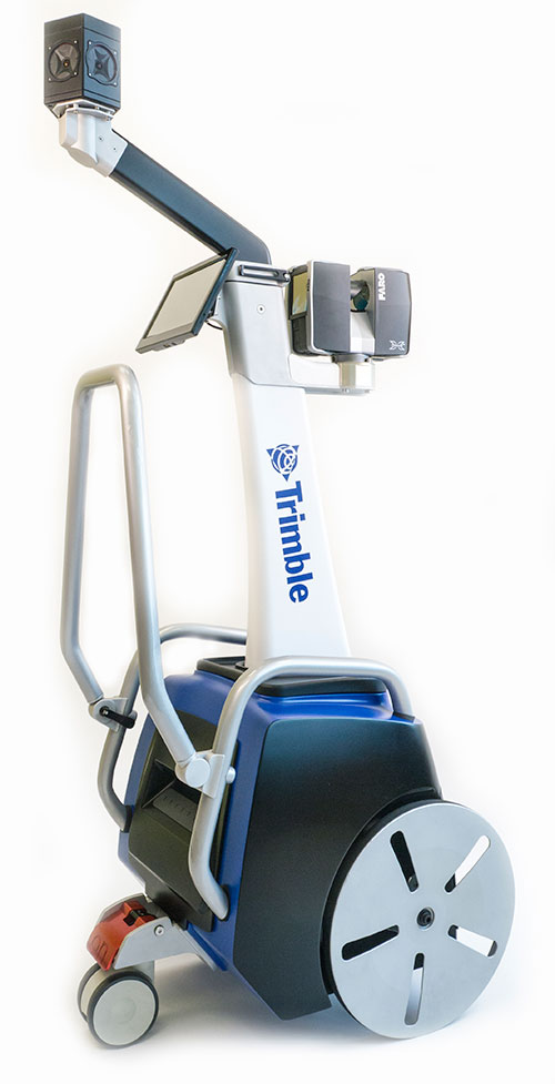
Trimble has introduced its next-generation Trimble Indoor Mobile Mapping Solution (TIMMS) that produces fast and accurate maps of difficult-to-navigate indoor spaces and translates them directly into 2D and 3D models of structured interiors.
TIMMS 2 is a fusion of technologies for capturing spatial data of indoor and other GNSS denied areas, the company said. It provides both lidar and spherical video, enabling the creation of accurate, real-life representations of interior spaces and all of their contents. The maps are geo-located, meaning that the real world positions of each area of the building and its contents are known and can be easily placed and oriented in a wide area model.
TIMMS 2 is smaller, lighter and more easily maneuverable than its predecessor. It can negotiate tight corners, closets and catwalks, and can be carried up and down staircases where no elevator is available for travel between building levels.
“The new Trimble Indoor Mobile Mapping Solution has been designed with greater emphasis on ease of use. It is very easy to maneuver, lift, ship and operate,” said Louis Nastro, director of Land Products at Applanix, a Trimble Company. “Our extensive experience with a broad range of projects with the previous generation TIMMS has led to a number of enhancements in data collection, processing and workflow management — making an indoor mapping project a seamless experience for users both pre- and post-mission. Whatever the building type and shape, TIMMS 2 can deliver exceptional results, both in accuracy and ease-of-use.”
Building on the success of the first-generation solution, TIMMS 2 also provides improved software workflow to manage the complete process from collection through post-processing to model production. Fully compatible with POSPac MMS, Applanix’ post-processing suite, TIMMS data can be presented in a variety of ways, including integration into Trimble Business Center and other infrastructure management or CAD packages.
Because of its increased efficiency, speed and ease-of-use, TIMMS 2 is an effective and high-productivity indoor mapping solution for buildings and facilities of all shapes and sizes, according to Trimble, including large or small areas, multi-level, industrial or commercial spaces. Users can obtain holistic 3D indoor geospatial views of all kinds of infrastructure including public buildings (government offices, schools, hospitals); industrial facilities (factories, warehouses); transportation hubs (airports, train stations); retail spaces (malls, concourses); entertainment venues (theatres, auditoriums, sound stages); and residential property (especially multi-occupancy high-rise buildings).
Maps and models of these spaces can be used for activities including revenue management and space planning; emergency preparedness and disaster planning; and historical building conservation and preservation. In addition, the base map provides a platform on which building owners and managers can serve location-based services.
Manufactured and sold by Applanix, TIMMS 2 indoor mobile mapping solution is available in the first quarter of 2016.
Below, Eric Liberty of Applanix, a Trimble company, gives an overview of Applanix’s POS AV, POS AVX 210 and TIMMS indoor mobile mapping system at INTERGEO 2015, which was held Sept. 15-17 in Stuttgart, Germany.
Trimble has introduced its next-generation Trimble Indoor Mobile Mapping Solution (TIMMS) that produces fast and accurate maps of difficult-to-navigate indoor spaces and translates them directly into 2D and 3D models of structured interiors.
TIMMS 2 is a fusion of technologies for capturing spatial data of indoor and other GNSS denied areas, the company said. It provides both lidar and spherical video, enabling the creation of accurate, real-life representations of interior spaces and all of their contents. The maps are geo-located, meaning that the real world positions of each area of the building and its contents are known and can be easily placed and oriented in a wide area model.
TIMMS 2 is smaller, lighter and more easily maneuverable than its predecessor. It can negotiate tight corners, closets and catwalks, and can be carried up and down staircases where no elevator is available for travel between building levels.
“The new Trimble Indoor Mobile Mapping Solution has been designed with greater emphasis on ease of use. It is very easy to maneuver, lift, ship and operate,” said Louis Nastro, director of Land Products at Applanix, a Trimble Company. “Our extensive experience with a broad range of projects with the previous generation TIMMS has led to a number of enhancements in data collection, processing and workflow management — making an indoor mapping project a seamless experience for users both pre- and post-mission. Whatever the building type and shape, TIMMS 2 can deliver exceptional results, both in accuracy and ease-of-use.”
Building on the success of the first-generation solution, TIMMS 2 also provides improved software workflow to manage the complete process from collection through post-processing to model production. Fully compatible with POSPac MMS, Applanix’ post-processing suite, TIMMS data can be presented in a variety of ways, including integration into Trimble Business Center and other infrastructure management or CAD packages.
Because of its increased efficiency, speed and ease-of-use, TIMMS 2 is an effective and high-productivity indoor mapping solution for buildings and facilities of all shapes and sizes, according to Trimble, including large or small areas, multi-level, industrial or commercial spaces. Users can obtain holistic 3D indoor geospatial views of all kinds of infrastructure including public buildings (government offices, schools, hospitals); industrial facilities (factories, warehouses); transportation hubs (airports, train stations); retail spaces (malls, concourses); entertainment venues (theatres, auditoriums, sound stages); and residential property (especially multi-occupancy high-rise buildings).
Maps and models of these spaces can be used for activities including revenue management and space planning; emergency preparedness and disaster planning; and historical building conservation and preservation. In addition, the base map provides a platform on which building owners and managers can serve location-based services.
Manufactured and sold by Applanix, TIMMS 2 indoor mobile mapping solution is available in the first quarter of 2016.
Eric Liberty of Applanix, a Trimble company, gives an overview of Applanix’s POS AV, POS AVX 210 and TIMMS indoor mobile mapping system at INTERGEO 2015, which was held Sept. 15-17 in Stuttgart, Germany.
POS AV is a hardware and software system specifically designed for direct georeferencing of airborne sensor data.
The POS AVX 210 is a GNSS-inertial solution designed for mapping with small and medium format cameras. The positioning components are now smaller and integrate MEMS technology.
TIMMS (Trimble’s Indoor Mobile Mapping System) captures spatial data of indoor and other GNSS-denied areas of all sizes and locations, according to Trimble. It provides both LiDAR and spherical video of a facility, enabling the creation of accurate, real-life maps or models of interior spaces.
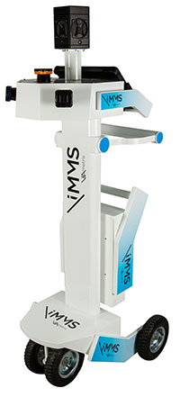
The iMS 3D indoor mapping system by Viametris uses an Ellipse-A by SBG for roll and pitch data.
SBG Systems will join Viametris in presenting a new 3D indoor scanning system at the INTERGEO trade show, which will be held Sept. 15-17 in Stuttgart, Germany.
The iMS 3D is a mobile 3D indoor scanner generating continuous point clouds. For this brand-new model of indoor mobile mapping system, or iMMS, Viametris chose SBG Systems’ miniature Attitude and Heading Reference Sensor (AHRS), the Ellipse-A. The iMS 3D is easier to transport, install and set up than previous iMMS. The iMS 3D also integrates new sensors, including the Ellipse-A from SBG Systems.
Based on the SLAM technology, the iMS 3D is equipped with three lidar profilers, each taking 40,000 points per second. The main lidar provides the horizontal profile, which also contributes to the continuous calculation of the iMS 3D position in the building. Two lateral lidars give vertical profiles, including the ceiling. While the user walks, pushing the iMS 3D at normal speed, the 3D profile of the room appears on the screen, since the system records 3D measurements of the same room. Easy to manipulate, one person is enough to survey every corner of the building with the iMS 3D.
During the survey, the 360-degree camera takes a spherical picture every two meters for a full documentation of the building. This solution makes indoor survey 10 times quicker than traditional methods usually using distance meters, Viametris said, adding that the iMS 3D delivers a combination of point density, acquisition speed and accuracy suitable for the building trade industry.
At the office, the user accesses a centimeter-level accuracy 3D survey as a point cloud and pictures by using the Viametris processing and browsing software. The user can import the point cloud in CAD software (Autodesk Revit, AutoCAD, MicroStation, Rhino, etc.) to easily produce 2D maps or 3D models. The point cloud can be colorized with the colors of the pictures taken during the survey, which greatly improves the environment understanding. Additionally, the user has access to contextual 360-degree pictures, making objects such as radiators, extinguishers or lights simple to distinguish and locate.
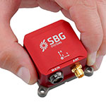
Ellipse-A.
Already integrated in other Viametris ultraportable technologies, the Ellipse-A has been chosen for this new generation of indoor mobile mapping system, or iMMS. “We integrated an Ellipse-A in our 2D system and were very happy with the results. It was obvious to us that the Ellipse-A will be part of our new iMMS,” said Jérôme Ninot, president of Viametris. The Ellipse-A is used to correct the horizontal profile. While the user is pushing the iMS 3D through the rooms, unevenness, slopes and ramps, cables or door thresholds can cause noise in the point cloud. The Ellipse-A keeps the point cloud clean by correcting the horizontal lidar data frames used to build the trajectory.
The Ellipse-A AHRS provides roll and pitch data accurate to 0.2° at 200 Hz. “The Ellipse sensors are much more efficient than the previous IG-500 product line,” said Mr. Ninot.
Keeping lidar and camera data precisely synchronized can be difficult because the camera focal time is susceptible to vary. In mobile scanning, even a slight latency might cause an offset. For example, the picture will not be located on the right place inside the point cloud. Viametris decided to connect the camera and the three lidars to the Ellipse-A to ensure a highly accurate and repeatable synchronization.
At INTERGEO 2015, the iMS 3D will be presented at stand # B4.049 and the ELLIPSE-A will be presented at stand # G4.079.
TomTom has begun a strategic partnership with indoor-mapping company Micello Inc., extending its range of mapping products to include indoor venues.
Integrating Micello’s maps and venue content gives TomTom’s business customers access to accurate pedestrian friendly indoor maps with points of interest data in venues worldwide.
“The indoor mapping functionality means that step-by-step guidance can be integrated into daily life for a wide variety of venues, including shopping malls, airports and retail stores,” said Charles Cautley, managing director, TomTom Maps. “By partnering with Micello our customers can now develop smarter apps and locations-based services helping users navigate with ease in and out of the car.”
“We’re excited to be partnering with TomTom, the global leader in navigation.” added Ankit Agarwal, CEO of Micello. “Our agreement means that TomTom’s business customers can use our indoor venue maps and incorporate the content into their automotive, online, or mobile solutions.”