Xsens launched its MTi 600-series of inertial sensors at Xponential 2019, which took place April 29-May 2 in Chicago. At the show, the MTi 600-series won a Technology Innovation Award from the Association for Unmanned Vehicle Systems International.
Tag: inertial sensors
-
Three-axis gyro launched for optical image stabilization

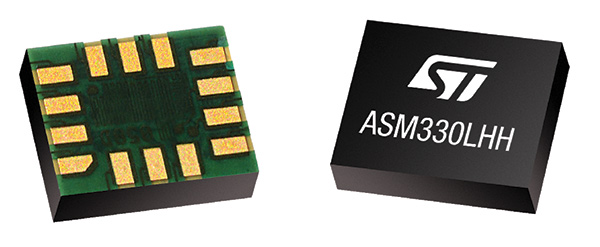
Photo: Gladiator Technologies Gladiator Technologies has introduced a three-axis, inertial rate system gyroscope. The G300D gyro is 0.67 cubic inches, low power and high speed, making it suitable for image stabilization applications, the company said.
The G300D has message timing under 150 microseconds and output data rates up to 8 kHz with external sync. A micro-electro-mechanical gyroscope, it has an ARW of <0.0028 degrees/sec/√Hz and an option for both 24 and 32-Bit LSB for exceptional resolution.
Users can configure the G300D to their desired configuration using a software development kit or through software protocols to simplify the integration process.
“The G300D, with a 250-Hz bandwidth, allows user to replace more complicated and expensive gyros for image stabilization applications,” said Rand Hulsing, chief scientist at Gladiator Technologies. “The three-axis package is also convenient for mounting in any orientation for tight space requirements.”
“The G300D product is a good example of our SX-series architecture, which has enabled Gladiator to extend our sensor fusion technologies into high speed applications with message latency under 150 usec,” said Lee Dunbar, chief software architect at Gladiator Technologies. “This output offers minimal phase lag like an analog sensor by virtually eliminating typical signal processing and digital conversion overheads.”
The G300D gyro is non-ITAR.
-

The role of GNSS in driverless cars
Authenticated localization in driverless cars
Growing awareness of the vulnerabilities of GNSS signals — weak, unencrypted and easily jammed or spoofed — have made GNSS less important to steering the driverless vehicle. What’s up with that?
Extensive visual map databases are being created that, when coupled with cameras, radars and lidars on the vehicle and processed by artificial intelligence (AI) algorithms, enable the driverless car to be steered much the way humans drive. Pattern recognition processing in the vehicle allows it to “read” street signs and recognize landmarks, registering its position on the map.
This is the way a person drives in his or her home town, where they always know their orientation and don’t need GNSS. The AI processing “brain,” with access to huge map databases, either through local storage or a network connection, will always be in its familiar home environment: continuously knowing its own position and properly oriented for navigation.
So, will GNSS become unnecessary in the car of the future? Probably not.
First, no one method of navigation is foolproof, and today, GNSS is our primary method of navigating our cars. It is a cost-effective, accurate way of determining position in real time, and with the integration of inertial navigation sensors to handle cases when GNSS is intermittently unavailable, it is improving.
Second, it is not just the car itself that needs to know its location for navigation, but also others outside the car. Ride-sharing apps like Uber and Lyft, car-sharing, usage-based insurance apps, dynamic toll charging, and parking apps all depend on knowing where the car is at all times. GNSS offers sufficient accuracy for all these apps by providing location coordinates. Therefore, a GNSS receiver will most likely remain in the car.
The case for jamming and spoofing
Recall, however, that one of the weaknesses of GNSS is its open, unencrypted format. It is becoming increasingly easier to spoof these signals. Car-sharing, usage-based insurance and dynamic toll charging apps all create a monetary incentive for fraud that can be implemented with a spoofer. For example, a car in a car-sharing network can report a fake position indicating that it is safely parked in a secure area — while in reality, a thief is busy driving it away.

(Image: Orolia) Let’s assume that all wireless connections to and from the car are secure. This is a reasonable assumption, although recently there have been demonstrations of carjacking via unsecure remote links. Standard SSL encryption, similar to what is used to enter credit card information on the internet, works well here. We have both the awareness and the technology now to prevent such carjackings from ever reoccurring.
However, even if communication links are secure, a GNSS spoofer in the car can fool the GNSS receiver into reporting a fake “safe” position right as it is being stolen. The same is true for insurance or toll apps. And the fraud does not have to be sophisticated. A simple, low-cost jammer can deny proper position just long enough to skirt payment. A secure location method is needed.
Other signals for localization
What would an ideal signal for localizing a driverless car look like?
- It needs to be much stronger than GNSS so it is not easily jammed.
- It needs to be encrypted so it cannot be spoofed.
- It must be ubiquitous, available worldwide.
- It must be reliable and robust — with 99.999% availability or better.
- It must be practical and priced for the mass-market automotive application.
Though accuracy is always important, the signal used for localization does not have to be as accurate as GNSS is today. Accuracy to 10s of meters is sufficient for all these applications needing fraud protection since it would not be used for steering the car, but rather, only localization. It can also be used in tandem with GNSS to authenticate a reported position when a GNSS signal is available.
Such a signal is available today, worldwide: STL (Satellite Time and Location). Carried on the Iridium satellites, it is a special purpose signal that is more than 30 dB stronger than GNSS and encrypted for anti-spoof protection. Decoding of this signal is available via a subscription model to users.
Here’s how it would work using a car-sharing example. A group of people subscribe to a car-sharing service that provides X number of cars to serve Y number of people, where X is less than Y. The service optimally schedules people when and where a car will be available. The service provider needs to know the whereabouts of the cars at all times to maximize utilization of the fleet, so every car has a GNSS receiver in it.
But to ensure the authenticity of these reports, they also have a secure localization receiver. This receiver is assigned a unique ID that is authorized to decode the encrypted signal. (Eventually, we expect this receiver and GNSS to converge into one device much the way multi-GNSS receivers operate today).
If a position report does not agree with the authentic localization report, the fleet manager can act to recover the car immediately. Insurance providers who cover secure localization-equipped cars would also give preferential rates as an anti-theft device.

(Image: Pavel Vinnik/Shutterstock.com) Could PRS do it?
The new Public Regulated Service (PRS) from Galileo is encrypted and could provide a similar level of authentication protection, if made available. However, it is still a weak GNSS signal that can easily be jammed. Of course, any signal can be jammed, even one that is a thousand times stronger than GNSS.
However, given the robust nature of a very strong signal, the managing system that is monitoring the cars — the insurance, toll or car-sharing system, for example — can alarm upon the loss of positioning information. Such alarms on a GNSS-only car would be frequent and often erroneous due to simple fades, yielding so many false alarms that it would render the monitoring system useless. But a loss of both the strong localization signal and GNSS would likely be considered suspicious and result in a valid alarm.
GNSS navigation is truly one of the great advances of the modern era, giving us precise time and location for any place in the world. Its two major weaknesses — that it is easy to jam and spoof — can be overcome by augmenting it with other stronger encrypted signals, such as STL, providing robust jam-resistance and positive authentication.
-
STMicroelectronics offers automotive-grade inertial sensor
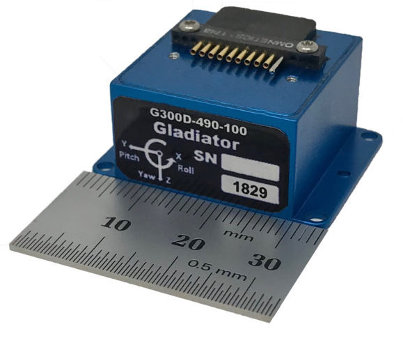
STMicroelectronics has introduced the automotive-grade ASM330LHH six-axis inertial sensor for super-high-resolution motion tracking in advanced vehicle navigation and telematics applications.
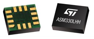
Photo: STMicroelectronics Serving demands for continuous, accurate vehicle location to support automated services, the ASM330LHH lets advanced dead-reckoning algorithms calculate precise position from sensor data if satellite signals are blocked, such as in urban canyons, tunnels, covered roadways, parking garages or dense forests.
Its advanced, low-noise, temperature-stable design enables dependable telematics services such as e-tolling, tele-diagnostics and e-Call assistance. Precision inertial data in six axes also meets the needs of advanced automated-driving systems, the company said.
Automotive component manufacturer Magneti Marelli has selected the ASM330LHH for advanced telematics systems, to be fitted as original equipment by global automotive groups in upcoming vehicle ranges.
For the ASM330LHH, as with all its MEMS sensors, STMicroelectronics owns the entire manufacturing process, from designing the sensors, through wafer fabrication, packaging, test, calibration and supply. Full end-to-end control enables STMicroelectronics to create high-performing sensors and assure customers of a robust and responsive supply chain, with rigorous end-of-line quality screening, the company said.
“STMicroelectronics is the largest supplier of MEMS sensors for automotive non-safety applications, such as navigation and telematics,” said Andrea Onetti, Analog, MEMS and Sensors Group vice president at STMicroelectronics. “Our latest-generation inertial sensor, the automotive-grade ASM330LHH, enables precise positioning for safer, smarter driving.”
Engineering samples will be available for evaluation by the third quarter of 2018, and volume production will begin the following quarter.
Further technical information on the ASM330LHH
- Temperature range up 105 degrees Celsius giving designers extra freedom to locate electronic controls in hot areas such as in smart antennas on the vehicle roof, or near the engine compartment.
- Ultra low noise allows greater measurement resolution by minimizing integration errors when positioning is reliant on sensors only.
- High linearity and built-in temperature compensation eliminate any need for external compensation algorithms over its operating range.
- Lowest power consumption in class, with features for optimizing power management if battery usage becomes crucial.
- Qualified according to AEC-Q100 automotive-grade robustness standard.
- Built on STMicroelectronics’ proven, proprietary ThELMA MEMS process technology, which enables integration of both the three-axis accelerometer and three-axis angular-rate sensor (gyroscope) on the same silicon for optimum yield, quality, and reliability.
- The electronic interface integrates the signal chain for both sensors on a single die using STMicroelectronics’ 130nm HCMOS9A technology.
- Reference designs, as well as STMicroelectronics’ Teseo satellite-positioning modules and related software are available. The dead-reckoning algorithm included with the Teseo III GNSS-receiver chipset already supports the ASM330LHH to generate a high-accuracy output suitable for autonomous navigation.
- Tiny, low-profile 3mm x 2.5mm x 0.83mm device for minimal impact on the size of any on-board module.
- Packaged as a leadless Land Grid Array (LGA) device.
-
SBG Systems showcases inertial sensors, MEMS INS, more at Xponential 2018
SBG Systems’ Christophe Nicolopoulos offers GPS World a rundown on its latest products, including the Apogee Series, the Ekinox 2 Series, the Ellipse 2 Series and Ellipse Micro Series, at Xponential 2018 in Denver.
-
LORD Sensing inertial sensors designed for dynamic environments
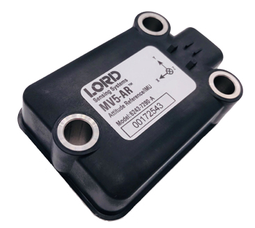
 LORD Sensing MicroStrain has launched a new line of rugged inertial sensors, which the company said will fill a void in the marketplace.
“The sensors respond to a market need for a sensing solution that offers better attitude and positioning accuracy and dynamic response in locations such as on the boom of an excavator or frame of a wheel loader,” said Chris Arnold, LORD Sensing product manager. “Customers are replacing traditional rotary and linear position sensors that provide less rich data on machine position and motion.”
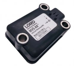
Designed for use in demanding environments for dynamic inclination and positioning, the MV5-AR inertial sensors are designed for off-highway and military vehicles; marine and mobile robot applications; and the autonomous vehicle market.
The rugged, compact, state-of-the-art inertial sensors utilize LORD Corporation’s proven fifth-generation high-performance industrial-grade solid-state six-degrees-of-freedom (6-DOF) micro-electromechanical (MEMS) accelerometer and gyro inertial sensor technology.
Already successfully deployed on ground robots and heavy-machinery, intended applications include autosteer and terrain compensation; dynamic incline detection (roll, pitch, rotation); vehicle stability and leveling; platform control, alignment and stabilization; operator feedback; and precision navigation.
The MV5-AR model has a compact and rugged reinforced PBT housing fully sealed for immersion, pressure wash (IP67, IP69K) as well as a rugged, reliable molded-in AMPSEAL 16 connector. Each sensor is fully calibrated and temperature compensated, the company said.
The MV5-AR models offer:
- Low-cost, compact size that is among the smallest form factor in its class.
- Full 360-degree measurement range about all axes; it can be mounted in any orientation.
- Full accuracy over the entire operational temperature range of -40°C to 85°C.
- CAN J1939 communication.
- Auto-adaptive extended Kalman filter for optimal dynamic accuracy.
- The MV5-AR provides inertial and slope J1939 messages in its standard configuration. Customized CAN protocols and messages are available.
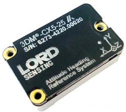 LORD Sensing has also expanded its GX5 portfolio to offer the 3DM-CX5 inertial sensor. With compact chassis or board mount option for embedded applications, the CV5 and CX5 are interchangeable with the same mounting footprint and communication protocol. Each sensor is fully calibrated and temperature compensated. Models offer:
- Low-cost, compact size and full 360-degree measurement range about all axes.
- Full accuracy over the entire operational temperature range of -40°C to 85°C.
- Auto-adaptive extended Kalman filter for optimal dynamic accuracy and on-vehicle performance.
-
Spoofing in the Black Sea: What really happened?
We’ve heard a lot in the news recently about GPS spoofing, mostly centred on the story of ship spoofing in the Black Sea. Between June 22-24, a number of ships in the Black Sea reported anomalies with their GPS-derived position, and found themselves apparently located at an airport.
What happened is open to educated conjecture. In this column, I’ll briefly cover the history of spoofing, its basic techniques, some spoofing tests that we conducted, and then return to the infamous Black Sea incident.
As part of my day-to-day work in navigation warfare, I do a fair amount of work in defensive anti-spoofing. Naturally, in order to test anti-spoof technology, it is necessary to also perform spoofing. It’s a delicate subject and, as with any topic involving defense or national security or critical infrastructure, there’s a balance to strike between responsible disclosure, how much information is released into the public domain, and so on.
In this article, I will stick firmly to information available in the public domain, lest I be accused of proliferating the threat, but this still gives us enough material to tiptoe around the subject for the benefit of our readers. I could have included more details about the spoofing attacks, but was advised to hold some back — it makes governments nervous. You can read some of the background in an excellent article by Norwegian broadcaster NRK and a Resilient Navigation and Timing Foundation press release. Similar GPS anomalies still continue to occur at various locations.
Let’s start with basic spoofing background, and we’ll return to the Black Sea incident at the end of the article.
A brief history of spoofing
Spoofing isn’t a new threat — it’s been around for decades. But only in recent years has it received so much public attention. As with jamming and anti-jamming technology, and most other topics in the GPS domain, spoofing finds its roots back in the days of Cold War radar. In those times, it was often known as “deception jamming,” where you would transmit fake radar returns to paint an incorrect picture on your adversary’s radar screen.
When GPS came along, it was understood at the time that the C/A code would be vulnerable to spoofing. It’s an open code, so anyone is free to reproduce it. That is, after all, what a GPS simulator is: a GPS spoofer. We legitimately test our GPS receivers by fooling them with fake signals from a GPS simulator.
Of course, this is precisely why legacy GPS satellites also transmit the military P(Y)-code, and continue to do so. The P-code offers improved accuracy, and some other benefits, but more importantly, it is modulated with the W encryption sequence to give us the encrypted P(Y)-code. Ever since the anti-spoofing module was set to the “on” state, unless you have the key, you are unable to directly spoof the P(Y)-code. (You can still perform a meaconing attack, though, where you simply record the transmitted satellite signals and retransmit them again. Although this kind of attack can’t be used to impose a particular scenario on a GPS receiver, it might still cause havoc in unwary receivers).
So. in the early days it can be argued that the spoofing threat was solved. It wasn’t until GPS became ubiquitous in the commercial and civilian domain that spoofing really raised its head again. The fact that the vast majority of GPS receivers in the world relied solely on the unencrypted C/A code became a cause for concern — especially where those GPS receivers were essential to critical infrastructure.
The threat of GPS spoofing was discussed at many conferences and behind many closed doors and, although most people agreed that spoofing was a theoretical threat, some people argued that in reality it was “simply too hard” to conduct a realistic spoofing attack. And therefore we should not worry ourselves about it.
It wasn’t until a couple of high-profile demonstrations were carried out by the University of Texas Radionavigation Laboratory that spoofing became front-page news once again. In 2012, the lab staff carried out an exercise at White Sands Missile Range where a GPS-guided drone was spoofed from a distance. The drone was fooled into thinking its altitude was increasing, causing it to compensate by dropping straight down. Then in 2013, the same team demonstrated how an $80 million yacht could be steered off course by means of a spoofing attack.
These exercises publicly demonstrated that spoofing was indeed a real threat, and could be done. But many people still believed that it was very hard to build the complex equipment necessary to perform the attack, and thus spoofing was out of reach for most potential criminals or terrorists.
Fast forward another two or three years, to when a new mobile phone game appeared. Pokemon GO became the game craze of the moment, where players would travel around the country with their phones, getting points by collecting creatures in an augmented reality world. It didn’t take long for people to dream up new ways of earning points in the game, without having to go to the effort of traveling around the world.
What if you could make your phone think it was somewhere else, without ever having to leave your bedroom? And thus, bizarrely, it was a mobile phone game that brought GPS spoofing into the mainstream.
The rise of the low-cost software-defined radio (SDR) has enabled “spoofing for everyone.” Today, the tool of choice for the casual user is often the HackRF or bladeRF. Couple small SDRs that cost around $200 with open-source GPS simulation software, and you have a basic spoofer. Plenty of websites detail how to perform basic spoofing, and at hacker gatherings, people can present how they spoofed a drone. These may not be the most sophisticated setups, but it’s good enough to do the job in many cases. With a better setup, which I won’t describe here, it’s possible to achieve a much more realistic attack, which will fool even the most shrewd and wary GPS receivers.
Spoofing basics
Let’s take a quick look at what it means to spoof GPS. A receiver searches for a satellite over a two-dimensional surface to find a correlation peak, and it must examine a range of Doppler frequencies and code offsets. An example is shown in Figure 1. Once the receiver finds the peak, the satellite is acquired, and it will then track the satellite as it moves and can demodulate the navigation data message.
When a spoofer comes along, it tries to recreate this peak. By doing so, and usually with little more power than the real satellites, the receiver will begin to track the spoofed signal. Once the spoofed signal is being tracked, the spoofer can begin to manipulate reality by slowly modifying the properties of the signal.
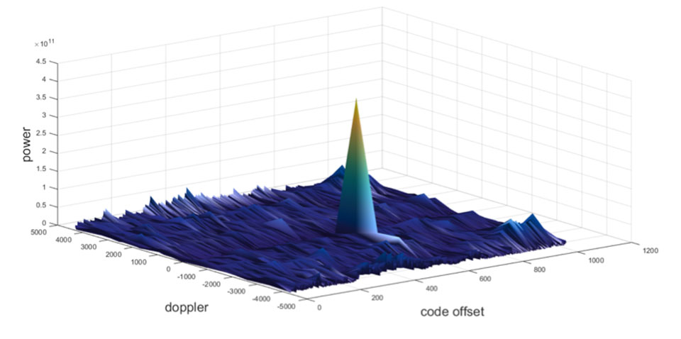
Figure 1. GPS correlation surface. (Image: Michael Jones) A poor spoofer doesn’t always align itself very well with reality, which essentially creates a second peak on the correlation surface. But a gullible receiver can still be fooled by this, and may lock on to false peaks.
The reality of spoofing and anti-spoofing
To understand the reality of spoofing and anti-spoofing, we carried out outdoor experiments at one of the Roke Manor trials areas (thanks go to my colleague Mike Wells for letting me use some of his results here).
In the first experiment (Figure 2), we spoof a commercially available mass-market receiver. The receiver is outside, reporting its correct location at Roke Manor. When we commence the spoofing attack, we are able to take control of the receiver. Once captured, we can then make the receiver appear to follow an arbitrary course. Here we make it wander off into the forest, spelling the word “roke” as it goes.
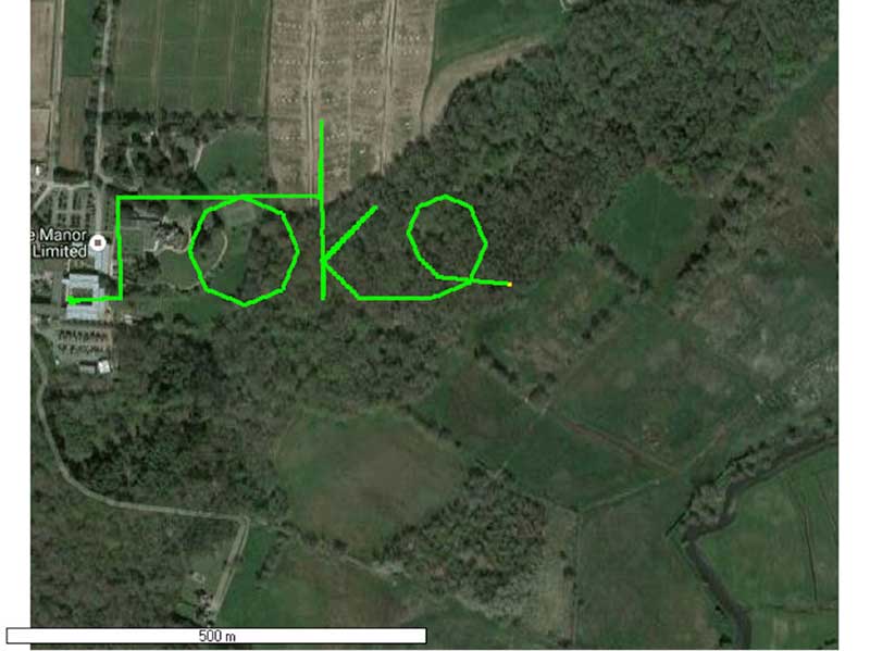
Figure 2. Spoofed GPS receiver appears to follow a course, whilst in reality being stationary. (Image: Michael Jones) In the next experiment (Figure 3), we place a conventional anti-jam antenna (a CRPA) on the receiver. What we observe, as you might expect, is that the basic CRPA offers no protection against the spoofing attack.
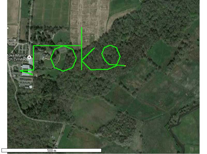
Figure 3. A GPS receiver is still successfully spoofed when protected by a conventional CRPA. (Image: Michael Jones) Now let’s make the experiment more interesting. We’ll move away from the basic commercial receiver, and replace it with a unit that contains not only a GPS receiver, but also a 3-axis accelerometer, 3-axis gyro, 3-axis magnetometer and a barometric sensor. An Extended Kalman Filter (EKF) performs an optimal fusion of the various sensors to yield the position solution.
The result, when we again try our spoofing attack, is shown in Figure 4. In short, the receiver is still successfully spoofed, despite the additional sensor inputs it offers.
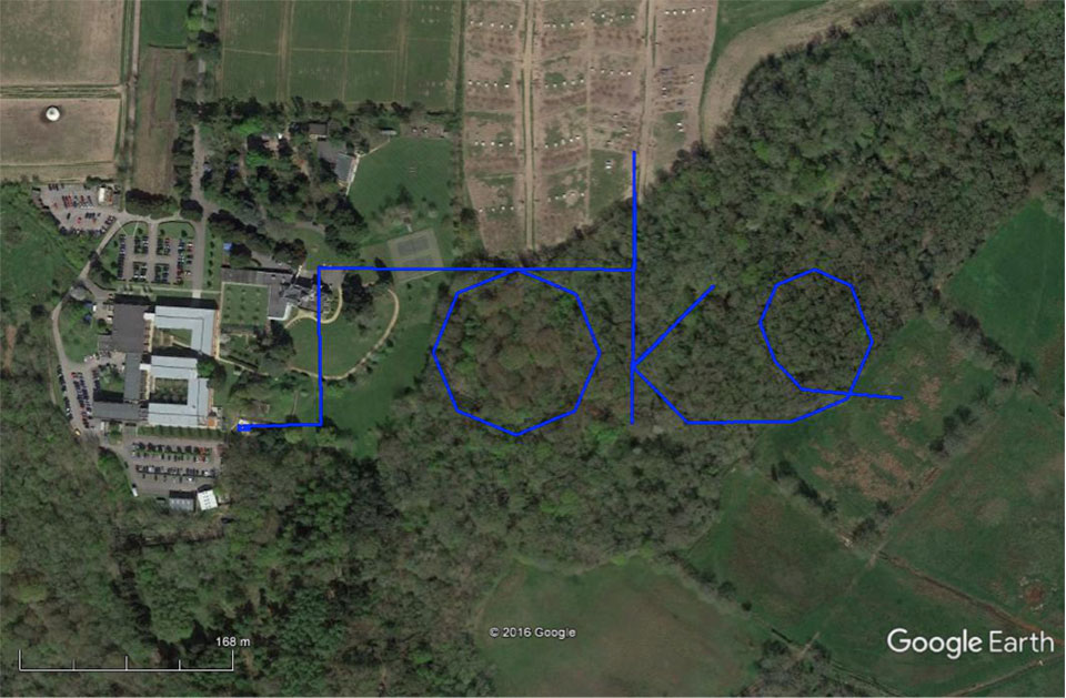
Figure 4. A GPS receiver with integrated inertial sensors is still spoofed. (Image: Michael Jones) Before everyone gets too depressed by the ease at which GNSS, and even GNSS fused with other sensors, can be spoofed, there are answers to this problem. Some decent, modern GNSS receivers contain a whole host of algorithms for detecting and ignoring spoof signals. The issue is that many legacy receivers are still in the field, and these can be extremely vulnerable indeed.
Another option is to use a more advanced CRPA, which offers anti-spoof capabilities. These adaptive antennas are able to correlate on the spoof signals, and then remove them based on direction of arrival. So, in our final experiment here, we use our commercial mass-market receiver again, and protect it with an anti-spoofing CRPA.
The result is shown in Figure 5. You can see that the receiver is briefly spoofed, and starts to wander off course. When the anti-spoof is enabled and kicks in, the position quickly drifts back to the true location and stays there. Good job.
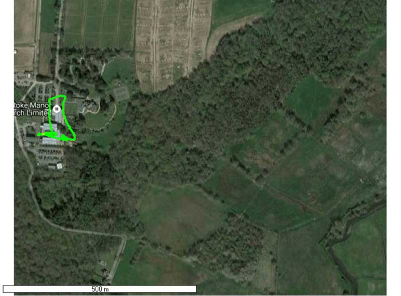
Figure 5. With an anti-spoof CRPA, the GPS receiver detects the spoofer and quickly returns to its true location. (Image: Michael Jones) Back to the Black Sea
Let’s finish by returning to the hot topic of the day. Did spoofing occur in the Black Sea back in June? Or was it a different form of interference? Could it have been a low-level jamming incident, causing the GPS receivers to report misleading information?
Without resorting to SIGINT (signals intelligence) data, and basing this discussion solely on public domain information and anecdotal evidence, I would say this was almost certainly a spoofing incident. A number of factors lead to this conclusion, and I’ll share some of them.
- Firstly, it didn’t happen to one ship – it happened to over 20 separate vessels. So it wasn’t a malfunctioning GPS unit; it was an external incident of some kind.
- Secondly, a large number of ships in the area reported identical or very close locations. This is a symptom of a large-scale spoofing attack. If it was a low-level jamming attack, then any misleading positions reported by vessels would typically have some randomness to them.
- Thirdly, ships reported that their positions would periodically “jump” from the true location to the incorrect location. Again, this is very typical behavior in some spoofing experiments: For various reasons, GPS receivers may temporarily lose lock on a spoof set of satellites, and then reacquire the real ones, and vice versa. This causes the characteristic random flipping between two well-defined locations.
If we accept that a GPS spoofing attack did occur, it brings us to the million-dollar question.
Who did the spoofing, and why?
What I’ll do here is a bit of a lightweight analysis exercise using public information and basic physics, and you can formulate your own conclusions.
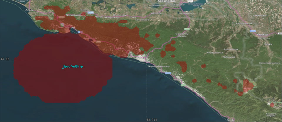
Let’s start by placing a ship, located in the Black Sea at 44°14.0’N 037°43.1E, which is the actual position of one of the reported spoofed vessels. For this example, I have placed a representative GPS antenna on the ship’s mast, with its antenna pattern shown.
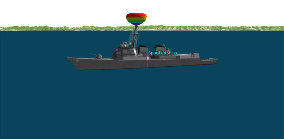
Figure 6. Victim ship in the Black Sea, with GPS antenna pattern shown. (Image: Michael Jones) To get a rough handle on the scenario, consider the possible propagation of the spoofing signal. As a first-order approximation, let’s assume a standard 4/3 Earth refraction model, with obstruction by terrain. That’s a reasonable assumption at this frequency: Any obscuration by terrain will block the spoof signal. Let’s also initially assume that our GPS antenna on the ship is mounted 38 meters above sea level, and our spoofing equipment is mounted on a mast 20 meters aboveground. From this information, we can plot a map of possible spoofer locations for this particular incident (Figure 7).

Figure 7. Possible spoofing source locations. (Image: Michael Jones) The first thing we might conclude from this is that the spoofing indeed originates from Russian territory, close to the Black Sea coast. To spoof the ship from further afield would require a much higher antenna, or even an airborne antenna. Which, of course, is possible, but then we would also expect vessels over a much wider area to report interference.
To me, it’s fairly conclusive that spoof GPS signals are being transmitted from this area, to make GPS receivers in the area think they are at an airport. The final question is: “Why would someone do this?” To answer this question, we must resort to educated speculation. Why would you want to spoof GPS receivers into thinking they are at an airport?
There’s one explanation that fits very nicely: drone defense. Many drones, especially those operated by casual users, have geofencing rules that prevent flights over airports and other restricted areas. So, if you were trying to perform aerial surveillance of the Russian border, your drone may suddenly think it was over an airport, and take action accordingly. The action taken depends, of course, on how the drone is programmed, but often includes “land immediately” or “return to launch point.” Certainly some of the drones we operate will immediately attempt to land if they find themselves in restricted airspace.
So if your drones are falling into the sea, you now have one idea why.
-
The changing face of defense PNT
I have mixed emotions as I write this column. Delighted, absolutely, to be given the opportunity to write for GPS World on topics that I am so passionate about; but also sad that we will not see any more articles from Don Jewell, whose excellent columns I followed so religiously over the years. I never had the opportunity to meet Don personally but, to me, he is irreplaceable. But let’s talk about the changing face of defense positioning, navigation and timing (PNT) — not in the editorial sense, but in the technology sense.
As we all know, PNT and GPS are no longer synonymous. With a host of innovative technologies on the horizon, PNT is about so much more than GPS these days, and the military knows it. Sure, GPS has been the workhorse of PNT for many years, and it’s not going anywhere anytime soon. I’ll be clear on that: GPS is not going anywhere. But it’s not a complete solution either.
Let me paraphrase what a friend in the infantry tells me, by saying GPS is a 60 percent solution to their navigation needs. What does that mean? Well, it goes something like this:
- 60 percent of the time: GPS is great, it does what we need.
- 20 percent of the time: We are indoors or underground, and GPS is simply not available.
- 15 percent of the time: We’re in an urban canyon. GPS availability is intermittent, and the accuracy is poor.
- 4 percent of the time: We’re in forests or dense vegetation, and GPS is sporadic.
- 1 percent of the time: GPS is jammed.
You can argue the numbers depending on the mission, but you get the idea. What, then, is the answer for the soldier? Well, first things first: We don’t want to reinvent the good 60 percent so, once again, GPS is here to stay. The question is how do we push past that 60 percent figure and get ourselves closer to 100 percent? Let’s go from the bottom up, and address GPS jamming.
Overcoming interference
The classic solution to jamming is an adaptive antenna, also known as a controlled radiation pattern antenna (CRPA). More on this another time but, for now, suffice it to say that CRPAs are a well-understood and mature technology, and can offer very high levels of jamming resistance.
The often-cited disadvantage of a CRPA antenna is its size, weight and power: As CRPAs employ multiple antenna elements, they are inherently larger and heavier. The electronics can pretty much be covered by a single chip these days, leaving the antennas themselves as the problematic aspect, but advances in antenna technology have also made big hurdles.
For airborne platforms, conformal antennas designed as part of the structure or fuselage can be used; whilst for the dismounted soldier, the trend is towards wearables, where the antennas may be an inherent part of the clothing or helmet design.
Aside from adaptive antennas there are a whole host of other techniques in your anti-jam kit bag, including receiver-based techniques.
It’s a numbers game
For forests and urban canyons, this is where multi-frequency multi-GNSS comes into its own. It really is a numbers game: The more constellations you use, the more satellites you can choose from, and the greater your chances of seeing enough satellites to derive a reasonable navigation solution. You also have more options for mitigating the effects of multipath and other errors.
Of course, this gives rise to a potentially difficult question for some governments: In defense applications, do you want to rely on foreign GNSS constellations as part of your PNT solution? The attitude here depends on your own country’s policy and a trade-off of perceived gains against perceived threats. The UK, for example, has chosen to embrace all available constellations and frequencies in future military navigation systems.
That’s probably about as far as GNSS gets you, because now we’re looking at the 20 percent of the time where the user is indoors or underground. In other words, environments where GNSS simply isn’t available. This 20 percent is perhaps more tricky to address, and is the realm of alternative and complementary PNT technologies.
Beyond GNSS
Fusing different sensor modalities to create a combined navigation solution is anything but a new idea. The benefits of combining GPS with an inertial sensor were recognized a long time ago, and this classic pairing continues to be the subject of research today.
The two technologies are highly complementary in various ways: GNSS offers absolute position, low short-term accuracy, and high long-term accuracy. On the other hand, an inertial sensor offers the opposite: relative position, high short-term accuracy, and low long-term accuracy. It’s a match made in heaven.
But whilst GNSS plus inertial may be a good choice for, say, airborne platforms, it doesn’t solve the in-building and underground problem. Without GNSS, you need something else.
Indoor navigation has been one of the hottest research topics of recent times, but there are really two types of indoor scenario: the first is when you’re in a shopping mall or airport. You can use an inertial sensor, Wi-Fi, mobile base stations, and various other bits of infrastructure to help you navigate.
The second scenario is the military one: You’re in an unfamiliar enemy compound or underground tunnel complex. In this case, there is no GNSS, no Wi-Fi, no mobile communications; and, for navigation, you can only really rely on the sensors you bring with you.
So what other sensor works underground, and complements inertial?
Visual/inertial integration
Visual odometry is an established, yet often overlooked, navigation technology that is undergoing a resurgence of interest, in both military and civilian applications. In simple terms, visual odometry uses sequential camera images to determine motion in a six degrees of freedom reference frame. Using either single or multiple cameras a platform can estimate both its 3D position and orientation, providing much the same information as an inertial sensor — but with a few added benefits.
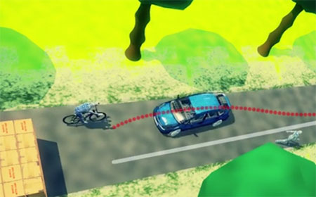
Visual/inertial sensing allows 3D reconstruction of a road incident. (Screenshot: Roke) Because cameras and associated vision-processing algorithms are capable of detecting corners and features, a 3D model of the environment in which the soldier is operating can also be built up. In other words, we can perform simultaneous localization and mapping (SLAM).
But like any navigation technology, visual odometry has its limitations. It likes well-defined features in the environment, such as corners, but can get confused by moving objects like trees and clouds. Its performance also depends on factors such as the quality of the camera and lens, and how well the system is calibrated. Like an inertial sensor, it provides a relative positioning solution and is subject to accumulation of errors over time. It’s a great technique, but it really comes into its own when combined with another navigation sensor, such as an inertial unit.
And it’s not just the military guys who are taking advantage of visual/inertial integration. Just take a look at Google’s Tango project, or what Qualcomm is doing, or Roke’s black box for driverless cars, to name but a few examples.
Bringing it all together
Over the course of the last decade or two, the operational landscape for soldiers has changed significantly, with far greater focus on urban warfare. The military realized some years ago that the answer to robust navigation for dismounted soldiers was going to require a range of sensor modalities: no single navigation technology is ideal in all environments. That’s why this has been the focus of so many defense programs of recent years.
By way of example, the UK Ministry of Defence (MoD) initiated a research program in 2013 called Dismounted Close Combat Sensors (DCCS). The contract addressed a range of soldier capabilities, one of which was the ability to provide reliable soldier position and orientation in all environments.
The DCCS programme evaluated a whole bunch of technologies, but eventually converged to an integration of three primary sensors: multi-constellation GNSS, a low-cost inertial measurement unit (IMU) and a video camera. The single monocular video camera was used to strap down the IMU, in a very tightly-coupled system. It makes sense: when GNSS is available, use it. When GNSS isn’t available, the integrated visual/inertial navigation sensor continues to provide both location and orientation for the duration of the mission. As it should be for a tightly integrated navigation system, the performance of the combined system outperforms any individual sensor in isolation.
Whilst integrated sensor systems enable our soldiers to position, orientate and navigate themselves, the performance of individual sensors continues to be pushed to new limits. Inertial technology is advancing all the time, and defense is again pushing the boundaries. Take a look at what DARPA is up to, as an example.
The missing ‘T’
Haven’t we missed something? Ah yes, there’s a “T” in PNT. So whilst there would seem to be various options for achieving a robust positioning and navigation solution, we mustn’t forget precise timing for those applications that need it. Quantum technology is flavor of the month here and, once more, the defense agencies are furthering developments: DARPA with its ACES program, and MOD/DSTL via the Quantum Technology Program, to illustrate just a couple of examples.
So whilst GPS will continue to remain the workhorse, defense PNT is migrating from GPS-only to being a many-faced beast. And I haven’t even gotten started on pseudolites, signals of opportunity, eLoran, and cooperative navigation.
The future of defense PNT looks pretty good to me.
-
SBG Systems features MEMS-based inertial sensors at AUVSI’s Xponential 2016
SBG Systems‘ Jack Mawson highlights the company’s MEMS-based inertial sensors at the Association of Unmanned Vehicles International‘s Xpontential 2016 show, held May 2-5 in New Orleans.
-
PNT Roundup: Navigating GPS-free, MEMS inertial trends and non-GPS tracking
Navigating GPS-free and MEMS inertial trends
Keynotes at February’s Inertial Sensors conference summarize initiatives to provide continuous, high-frequency and high-accuracy position spanning GPS outages or obstructions.GPS-Free. Robert Lutwak, program manager at the U.S. Defense Advanced Research Projects Agency (DARPA), spoke on “Precise Robust Inertial Guidance for Munitions: Navigating in a GPS-free World.”
Over the past decade, the DARPA Micro-Technology for Position, Navigation, and Timing (micro-PNT) program developed low-CSWaP inertial sensors as a backup or “flywheel” PNT solution for GNSS augmentation, validation and holdover in obfuscated environments. New programs, such as the Precise Robust Inertial Guidance for Munitions (PRIGM) program, seek to ruggedize and deploy devices developed under micro-PNT and to extend the performance to support longer and more dynamic mission scenarios. In addition to maturing micro-electro-mechanical systems (MEMS) and atomic technologies developed under micro-PNT, PRIGM is exploring new sensing modalities and architectures, including those enabled by integrated photonics and by the tight integration of photonic and MEMS technologies.
Accuracy One-Thousandfold. Lutwak also gave an overview of DARPA’s new Atomic Clocks with Enhanced Stability (ACES) program. A technology challenge budgeted for up to $50 million, ACES’ goal is to design and build a new generation of palm-sized, battery-powered atomic clocks that perform up to 1,000 times better than the current generation — DARPA’s Chip-Scale Atomic Clock.
The new clocks must fit into a package about the size of a billfold and run on a mere quarter-watt of power. Success will require advances that counter accuracy-eroding processes in current atomic clocks, among them variations in atomic frequencies that result from temperature fluctuations and subtle frequency differences that can occur if the power shuts down and then starts up again.
“It will take a collaboration of teams with skill sets from diverse fields, including atomic physics, optics, photonics, microfabrication and vacuum technology, to achieve the unprecedented clock stability that we seek,” Lutwak said.
MEMS Transition. Stephen Breit, director of engineering for Coventor, gave his predictions for the “Future of the Commodity MEMS Inertial Sensor Design and Manufacturing.”
Emerging trends that could lead to disruptive changes include commoditization of MEMS process technology, consolidation of advanced semiconductor technology, More-than-Moore integration, and the Internet of Things (IoT). These trends motivate industry efforts toward a transition similar to the one that occurred in the CMOS industry: from integrated device manufacturers to a fabless/foundry business model.
This will require a design automation flow that provides a platform for process design kits (PDKs) that foundries can supply to their fabless customers.
Exploiting fingerprints, other smartphone features
Tiny irregularities in an Android or iPhone’s accelerometer can be turned into a unique signature to track users, Stanford researchers found in 2013. These flaws essentially fingerprint an individual smartphone and allow it to be traced. Highly focused activity since then, some of it summarized here, has advanced the frontiers of non-GPS tracking. Developments could prove interesting to privacy advocates, online marketers and law enforcement.Security researcher Hristo Bojinov demonstrated how, in a matter of seconds, he induced his smartphone to give up its “fingerprints.” Code running on a website in the device’s mobile browser measured the tiniest defects in the device’s accelerometer, producing a unique set of numbers — exploitable to identify and track most smartphones. Marketers could use the ID the same way they use cookies to identify a particular user, monitor their online actions and target ads.
The research team was also able to identify phones using their microphones and speakers. They found they could produce a unique frequency response curve, based on how devices play and record a common set of frequencies.
Amplifiers and Oscillators. A team at the Technical University of Dresden developed a tracking method that exploits variations in the radio signal of cell phones. The collection of components such as power amplifiers, oscillators and signal mixers can all introduce radio-signal inaccuracies.
Bojinov and colleagues presented further work at the RSA Conference 2015, in “Sensor ID: Mobile Device Identification via Sensor Fingerprinting.” Among findings:- We have found ways to construct a device ID by sensor fingerprinting.
- All the sensors’ fingerprints may sum up to enough bits to identify all devices.
- It is hardware dependent.
- It can be used by web application.
A related presentation stated that “this is only the beginning. Many more unexpected information leakages will be found in the coming years. Treat every app you install as having ‘root’ on the phone. And think twice before installing that ‘harmless’ game.”
Engineers at Robert Bosch GmbH in Germany focused on MEMS-based gyroscopes and showed via wafer-level measurements and simulations that it is feasible to use the physical and electrical properties of these sensors for cryptographic key generation, a key requirement for full rollout of the Internet of Things.
Teams from Virginia Tech and the University of Essex have published papers detailing similar approaches, basically turning this vulnerability into a tool. “We prove that device identification can be generated by using the accelerometer found in many pervasive devices,” wrote the Essex researchers. “Our experiments are based on a set of health sensors equipped with a MEMS accelerometer. Periodic readings are obtained from the sensor and analyzed mathematically and statistically to generate a stable ICMetric number.”
Alissa Fitzgerald aided in assembling this overview report.