When the U.S. Air Force shot down a Chinese balloon flying at 60,000 ft (11.4 miles) on Feb. 4, the incident raised many questions about international security, international law, U.S.-China relations and technology. Among them, where is the end of a nation’s airspace — the portion of atmosphere it controls above its territory? Its horizontal boundary corresponds to that of its land border and territorial waters, which extend 12 miles out from its coastline. However, there is no international agreement on the vertical boundary.
The 1967 Outer Space Treaty — to which the United States is a party and which bans “appropriation” of outer space by any nation — omits a definition of “outer space” because none of the major powers wanted to limit their own freedom of action in space. At a United Nations meeting in Vienna in 2001, the U.S. delegation said, “Our position continues to be that defining or delimiting outer space is not necessary.”
The United Nations has historically accepted as the boundary of space the Kármán line, at an altitude of 62 miles above mean sea level. It roughly marks the altitude where traditional aircraft cannot effectively fly using lift generated by Earth’s atmosphere, because the air there is just too thin. The Fédération Aéronautique Internationale agrees with this definition.
Some countries have adopted a definition for their own legal purposes, usually based on either the Kármán line or on the altitude at which orbital flight is possible without utilizing atmospheric lift. As a courtesy, a state launching a space vehicle that will traverse another state’s territory during its sub-orbital flight will notify the overflight state.
The U.S. military and NASA on the other hand, define space to begin at 50 miles above Earth’s surface. “Pilots, mission specialists, and civilians who cross this boundary are officially deemed astronauts,” according to the U.S. Department of Commerce’s National Environmental Satellite Data and Information Service.
Escaping Earth’s atmosphere entirely is another story. It requires traveling at least 600 miles, to its outermost layer, where violent solar winds have greater sway than air. If that were the definition of space, however, the Space Shuttle (which orbited up to 200 miles up), the International Space Station (205 miles to 270 miles), active Earth observation satellites (280 miles to 500 miles), some of the National Oceanic and Atmospheric Administration’ s polar-orbiting satellites (540 miles) and most scientific satellites, including nearly all of NASA’s Earth Observing System fleet, would not be considered spacecraft! Lower orbits have significant air-drag, which requires frequent orbit re-boost maneuvers.
There’s no question that GPS satellites, orbiting at an altitude of about 12,550 miles, are in space. That is why they are acquired, sustained, and operated by the U.S. Space Force (USSF), established in December 2019 as the newest branch of the U.S. armed forces. Its mission is to organize, train and equip space forces to protect U.S. and allied interests in space and provide space capabilities to the joint force. As the USSF grows, we’ll hear more about it.
Feb. 4 saw the news networks alive with sometimes wild reports about UFOs, UAVs and then a balloon. Balloons are used for weather forecasting on a regular basis, launched daily into the stratosphere with payloads gathering wind speed and direction, temperature, humidity, pressure and, of course, position.
Synchronized twice a day at about 900 locations around the world, balloons are released into the stratosphere gathering essential atmospheric data to feed our weather forecasts. Reaching altitudes of 20 miles, these balloons often drift on winds as far as 125 miles from the release point, broadcasting measurements from their onboard sensors.
At first, maybe North American Aerospace Defense Command (NORAD) thought the balloon crossing into Alaska’s airspace was just one of these high-altitude weather prediction vehicles. Aircraft were apparently scrambled, and initially it was decided there was no threat, so the balloon was allowed to continue and enter Alaskan airspace. It was detected and subsequently tracked by both the United States and Canada for some time as it continued to drift on the jet stream over the border into the lower 48. Then, people in and around Billings Montana (home to one of the nation’s three nuclear missile silo fields at Malmstrom Air Force Base) started to send in reports of a very large balloon high overhead — according to one observer with a high-resolution camera, it even seemed to be stationary for 35 minutes.
Apparently, by the time the good folks in Montana were looking up, the Pentagon had decided the balloon was a Chinese surveillance vehicle. To get this detail, one or more U-2 high altitude reconnaissance aircraft had been dispatched to investigate. The collected U-2 information spotted markings of a Chinese manufacturer on the 200-foot-tall balloon. A payload the size of a small passenger jet dangled some 20 feet below the balloon canopy. It had several antennas of various configurations. A huge solar panel was attached — presumably to power its suite of surveillance sensors.
The Federal Aviation Administration (FAA) ordered a ground stop for all aircraft traffic at the Billings airport while decisions were made about downing the balloon or allowing it to proceed.
Meanwhile, it may seem obvious that both the United States and China have developed, launched and make use of surveillance satellites. I imagined that a couple of dozen of these space vehicles would be buzzing over not only each other’s landmass, but also surveilling dozens of other countries as they orbit the whole planet.
What I found was a report that China had at least 260 such orbital observation platforms in 2022, and the United States has even more. Isn’t that enough without resorting to lower-tech balloons?
It’s possible that some electronic transmissions are short range and would not be detected by surveillance satellites operating in geosynchronous orbit (22,000 miles out), or even at 300 miles where the International Space Station (ISS) and most surveillance satellites hang out. So, a slow-moving balloon at 20 miles up might be ideal to “sniff” ground transmissions from sensitive military installations, and if you could control the balloon to hover, all the better to pick up radio signals. Could the gathering of transmission data somehow be used to geo-locate the source? It’s something the U.S. military may be working on, too, as it is reportedly also building a fleet of autonomous dirigibles and balloons.
According to press reports, the United States decided not to immediately take down the balloon, even though it subsequently discovered its surveillance capabilities. Not only was there concern over debris falling on populated areas but allowing the balloon to continue its flight over the United States provided an opportunity to observe its behavior and gather useful information. U.S. bases along its path apparently shut down all communications in sequence, as the balloon passed overhead.
The balloon was apparently found to be transmitting – presumably reporting on where it was and what it had detected. But, at some time transmissions ceased, possibly when U.S. Air Force activity was detected nearby.
The take-down off Myrtle Beach
An F-22 flew to almost the same altitude as the balloon and fired an AIM-9X Sidewinder missile into it, leaving the payload to tumble from 60,000 feet into the shallow (50-foot deep) Atlantic Ocean off Myrtle Beach, South Carolina. Recovery boats were already on hand to pick up the collapsed canopy, and to begin locating the electronics payload on the seabed. At time of writing, the U.S. recovery effort has yet to inform us on finding the key electronic payload, which would go a long way to confirming the intended mission for the balloon.
Image: Screenshot of CNN news coverage
Strange, but a couple of days later over Canada, F-22s were again in action to take down a “cylindrical object” detected at 40,000 feet — an altitude posing a danger to airline traffic. Little has been released on what this object might have been — could it possibly be a re-entering piece of space debris? Again, debris recovery and analysis is underway, and we patiently wait for a public report about what this was all about.
What have we learned?
Both China and the United States operate huge fleets of surveillance satellites gathering intelligence daily about each other’s capabilities and those of other countries. Both China and United States have also invested in surveillance balloons, but China is the only country to send one over U.S. territory.
There may have been earlier balloon incursions, which are only now being reported. The U.S. response was initially to determine the configuration of the balloon and its payload, then to allow its journey along the jet stream to continue. The United States has said the balloon did not uncover anything already available by other means, but recovery and analysis of the payload would presumably confirm this announcement.
China is not happy about the U.S. takedown of a harmless, stray weather balloon. And what the heck were F-22s shooting at in Canada?
We’ll tell you more when we learn more….
Tony Murfin
GNSS Aerospace
Editor’s Note: Since the initial instance of an unidentified object floating across U.S. airspace — later identified as a Chinese surveillance balloon — three additional unidentified aerial objects were spotted in North American airspace. One was spotted in Alaska, one in northern Canada and one over the Great Lakes region. All three were shot down by U.S. fighter jets out of caution.
Russia warned it could blow up 32 GPS satellites with its new anti-satellite technology, ASAT, which it tested Nov. 15 on a retired Soviet Tselina-D satellite, according to numerous news reports.
Russia then claimed on state television that its new ASAT missiles could obliterate NATO satellites and “blind all their missiles, planes and ships, not to mention the ground forces,” said Russian Channel One TV host Dmitry Kiselyov, rendering the West’s GPS-guided missiles useless. “It means that if NATO crosses our red line, it risks losing all 32 of its GPS satellites at once.”
The International Space Station (ISS) Flight Control team was notified of indications of a satellite breakup, causing 1,500 pieces of debris to threaten the station. “Due to the debris generated by the destructive Russian Anti-Satellite (ASAT) test, ISS astronauts and cosmonauts undertook emergency procedures for safety,” said NASA Administrator Bill Nelson.
“With its long and storied history in human spaceflight, it is unthinkable that Russia would endanger not only the American and international partner astronauts on the ISS, but also their own cosmonauts,” Nelson said. “Their actions are reckless and dangerous, threatening as well the Chinese space station and the taikonauts on board. All nations have a responsibility to prevent the purposeful creation of space debris from ASATs and to foster a safe, sustainable space environment.
“Russia has demonstrated a deliberate disregard for the security, safety, stability and long-term sustainability of the space domain for all nations,” Gen. James Dickinson, commander of U.S. Space Command, said. “Russia’s tests of direct-ascent anti-satellite weapons clearly demonstrate that Russia continues to pursue counterspace weapon systems that undermine strategic stability and pose a threat to all nations.”
Photo: Stanislav Ostranitsa/iStock/Getty Images Plus/Getty Images
NASA’s Space Communications and Navigation (SCaN) program is developing capabilities that will allow missions at high altitudes to take advantage of GNSS signals for timing and navigation, including the Artemis missions to the Moon.
Interoperability of the GNSS constellations will be key for spacecraft at higher altitudes where GNSS signals are less plentiful. The program will rely on the four global constellations (GPS, Galileo, GLONASS and BeiDou) and the two regional systems operated by India and Japan.
SCaN is supporting flight experiments that will help develop multi-GNSS capabilities for spacecraft, such as Bobcat-1, developed by NASA’s Glenn Research Center in Cleveland and Ohio University.
Bobcat on the Prowl
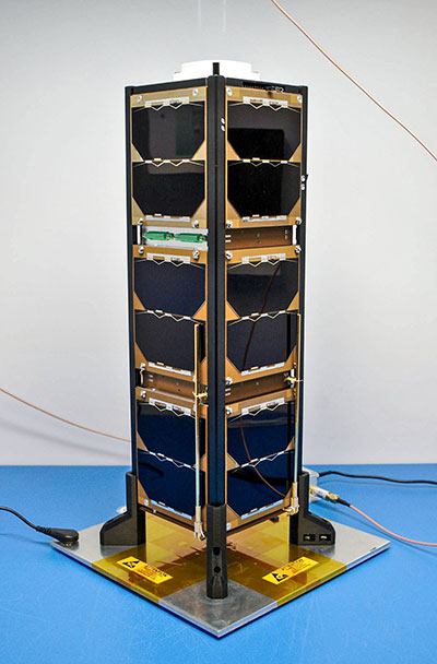
Bobcat-1, shown with its deployable antenna stowed, will experiment with the GNSS inter-constellation time offset from low-Earth orbit. (Photo: NASA)
Bobcat-1 was selected by the CubeSat Launch Initiative in 2018 to study GNSS signals from 250 miles overhead. The small satellite launched to the International Space Station aboard a Northrop Grumman Cygnus spacecraft on Oct. 2, 2020.
On Nov. 5, the space station released the CubeSat to begin its mission. The spacecraft will orbit for about nine months, measuring signals from different GNSS constellations. Engineers will use these measurements to better understand GNSS performance, specifically focusing on timekeeping variations between the constellations.
“GNSS users at high altitudes see fewer satellites,” said Bobcat Co-Principal Investigator Frank Van Grass of Ohio University. “Time offsets between the constellations can be measured by the CubeSat and provided to these users to improve their positioning performance,”
SCaN Testbed
Bobcat-1 builds on the legacy of the SCaN Testbed, which demonstrated multi-GNSS capabilities on the space station from 2012 to 2019. The GPS and Galileo Receiver for the International Space Station (GARISS) — an instrument developed in collaboration between NASA and ESA (European Space Agency) — received signals from both GPS and Galileo, the GNSS constellation operated by the European Union.
The SCaN Testbed prior to launch to the International Space Station. (Photo: NASA)
The SCaN TestBed also laid the foundation for the Lunar GNSS Receiver Experiment (LuGRE), a Commercial Lunar Payload Services payload being developed in partnership with the Italian Space Agency. The payload will receive signals from both GPS and Galileo and is expected to obtain the first-ever GNSS fix on the lunar surface.
GNSS PNT Policy and Advocacy
While NASA engineers develop the technologies necessary for multi-GNSS navigation at ever-higher altitudes, the SCaN team works with stakeholders in the U.S. government and internationally to advance GNSS interoperability in the policy sphere. They consult on the United Nations International Committee on GNSS, helping develop additional capabilities in the Space Service Volume and beyond.
NASA recently worked to publish GPS antenna patterns from GPS satellites that launched between 1997 and 2000, collaborating with the U.S. Space Force, the U.S. Coast Guard and Lockheed Martin, who built the satellites. The PNT team is also working to facilitate publication of antenna patterns for more recent GPS satellites.
With this data, mission planners can better assess the performance of GNSS in high-Earth orbit and lunar space. This forthrightness also encourages other GNSS providers to be similarly transparent.
The Goddard PNT policy team received a 2019 Agency Honor Award for their advocacy of NASA’s interests in GNSS. From let are Frank Bauer, Jenny Donaldson, J.J. Miller, Ben Ashman and Joel Parker. Not pictured, Lauren Schlenker. (Photo: NASA)
“GNSS capabilities continue to revolutionize the ways spacecraft navigate in near-Earth space and beyond,” said NASA navigation engineer Joel Parker. “NASA’s longstanding relationships with the GNSS providers have advanced these capabilities to new heights and support the Artemis missions on and around the Moon.”
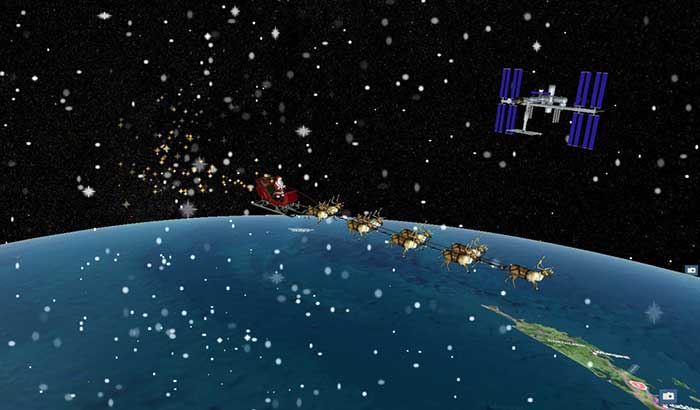
Santa Claus will be performing a ceremonial fly-by of the International Space Station (ISS) on Dec. 24. The visit will honor the 20th anniversary of continuous life on the ISS, a milestone achieved in November.
The official NORAD Santa Tracker at NoradSanta.org will allow users to track Santa’s journey all day on Dec. 24. New for this year, visitors will be able to see the ISS orbiting the planet in its precise real-time location by zooming out on the 3D Santa Tracker app. Other updates include additions to Santa’s traditional garb, including a face mask and space helmet.
Santa’s sleigh flying past the International Space Station on a precise digital twin of the Earth built by Cesium. (Photo: Cesium)
“The ISS is a spectacular example of what humans can accomplish when we work together,” said Hannah Pinkos, lead developer of the app. “2020 has been a tough year, but I think this special trip is Santa’s way of reminding us to believe in ourselves.”
NORAD, the North American Aerospace Defense Command, is a United States and Canada bi-national organization that defends North America by tracking objects flying in and around its airspace 24 hours a day using radar, satellites and fighter jets. Each year, it joins corporate partners in taking on a special mission to also track Santa’s sleigh. The app shows Santa’s position reflected on a digital twin of the Earth provided by Cesium, a Philadelphia-based geospatial software company.
“Cesium is rooted in aerospace, so it’s especially meaningful to us that our technology will allow millions of people to enjoy this event in real-time from the safety of their homes,” added Cesium CEO Patrick Cozzi.
The months-long wildfires raging in Australia have killed at least 25 people. Millions — possibly 1 billion — animals have died. More than 2,000 houses have been destroyed. Around 150 fires are still burning in New South Wales and Queensland, with hot and dry conditions accompanied by strong winds fueling to the fires’ spread.
With this conflagration rocking the continent down under, satellite imagery has become important to understanding the scope of the disaster. Here are some of the recent captures.
As seen from the ISS
“Talking to my crew mates, we realized that none of us had ever seen fires at such terrifying scale,” European Space Agency astronaut Luca Parmitano tweeted on Monday, sharing photos taken from the International Space Station.
The astronaut posted images showing what he described as “an immense ash cloud” captured at the time the ISS was flying toward sunset.
An immense ash cloud covers Australia as we fly toward the sunset.
Another social media image, shared widely, was interpreted as a map showing the live extent of fire spread, with large sections of the populous eastern coastline molten red. Because of widespread misinterpretation, the original poster then explained that the image was a 3D visualization and not a photograph of Australia, and showed some areas where fires have been extinguished.
NASA and the U.S. Geological Survey’s Landsat 8 satellite imagery from Jan. 9 shows Kangaroo Island, home to nature reserves. The images were taken using the Operational Land Imager (OLI) on Landsat 8. Using natural-color observations, the images show burned land and thick smoke covering the island, of which at least 156,000 hectares have burned.
Photo: NASA/USGS
The U.S. National Oceanic and Atmospheric Administration (NOAA) satellites are also capturing images, including the resulting plumes of smoke.
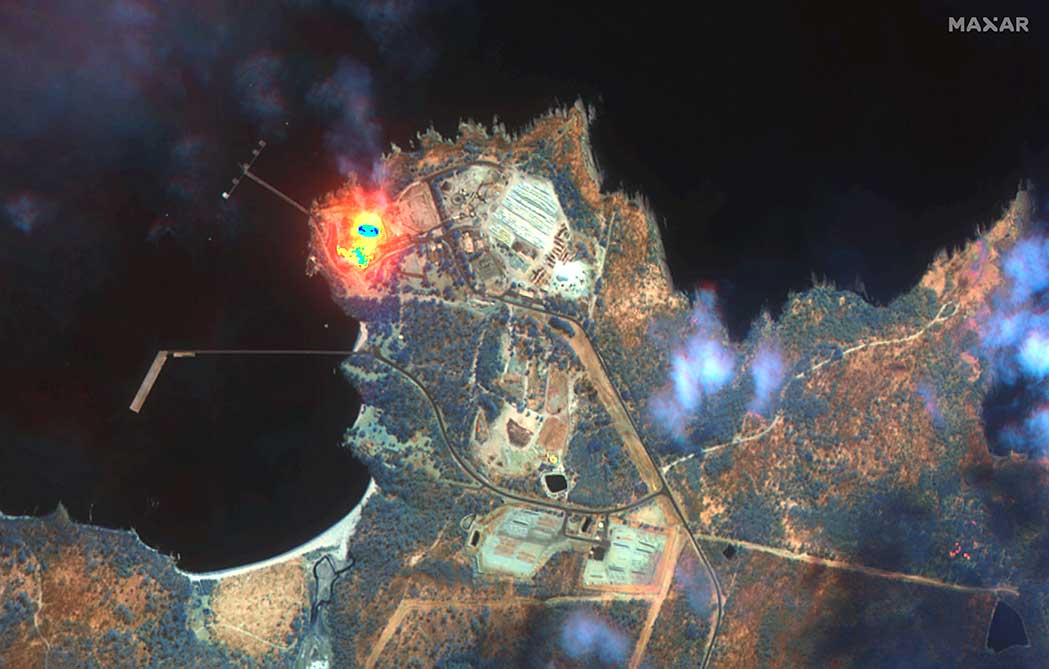
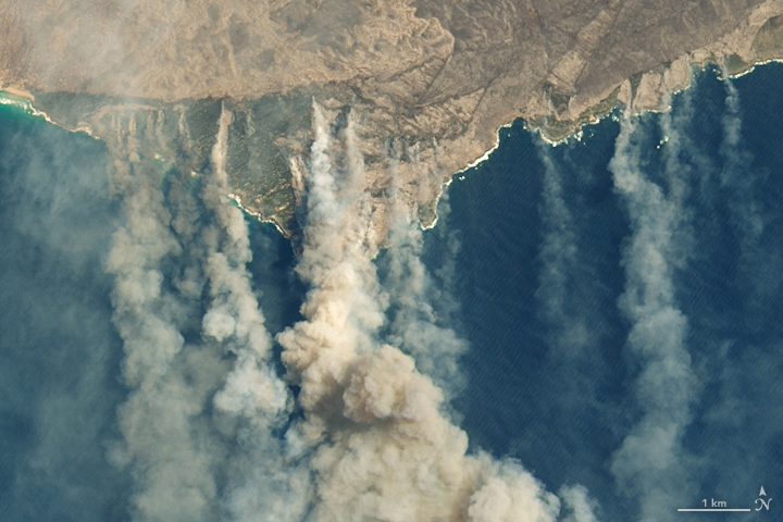
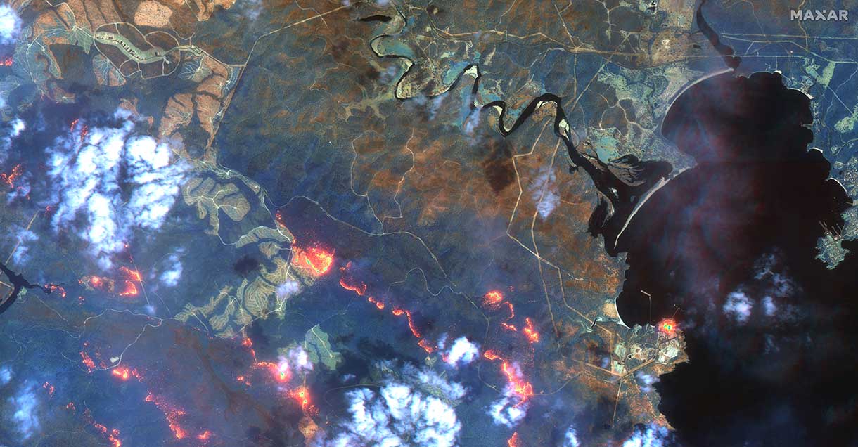
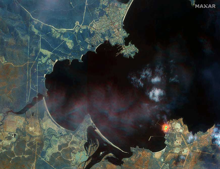
Maxar collected satellite imagery Jan. 12 of the wildfires in New South Wales (NSW). The imagery shown below focuses on the area near the town of Eden, and demonstrates the value of the shortwave infrared (SWIR) sensor.
In an image taken with Maxar’s normal RGB color imagery, the smoky air prevents a clear view of the fires and the hot spots. With Maxar’s WorldView-3 satellite, however, the team is able to penetrate through the smoke using its SWIR sensor for a detailed look at the fire lines and burned vegetation.
With SWIR imagery, burning areas are apparent and show up in a glowing orange-red. Healthy vegetation shows up in shades of blue, and burned vegetation appears in shades of brown.
Satellite Photo: :ESA
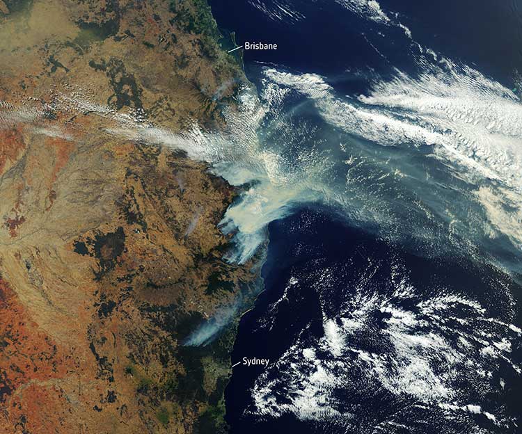
Copernicus Sentinel-3 imagery
Europe’s Copernicus Sentinel-3 mission has captured the multiple bushfires burning across Australia’s east coast.
In the above image, captured on Nov. 12, 2019, at 23:15 UTC (Nov. 13, 09:15 local time), the fires burning near the coast are visible. Plumes of smoke can be seen drifting east over the Tasman Sea. Hazardous air quality owing to the smoke haze has reached the cities of Sydney and Brisbane.
Flame retardant was dropped in some of Sydney’s suburbs as bushfires approached the city center, and many residents were evacuated. Firefighters continue to keep the blazes under control.
The Copernicus Emergency Management Service – Mapping was activated to help respond to the fires. The service uses satellite observations to help civil protection authorities and, in cases of disaster, the international humanitarian community, respond to emergencies.
Quantifying and monitoring fires is fundamental for the ongoing study of climate, as they have a significant impact on global atmospheric emissions. Data from the Copernicus Sentinel-3 World Fire Atlas shows that there were almost five times as many wildfires in August 2019 compared to August 2018.
The billions of interconnected devices and sensors embedded in other devices, vehicles and even humans that collectively constitute the much-heralded internet of things (IoT) collect and share data used in myriad applications. This requires them to know their location, which is a challenge in GPS-denied environments, such as most indoor locations, tunnels and urban canyons.
A new approach helps networks of smart devices cooperate to find and communicate their positions in such environments. This “localization of things” could be helpful in applications ranging from autonomous vehicles to asset tracking, from supply-chain monitoring to smart cities and real-time mapping.
Traditional network localization methods estimate a single value for each geospatial variable, such as the distance between two nodes. Therefore, accuracy drops sharply in environments where multipath, a limited view of the sky, and other problems severely degrade GNSS and wireless signals. A paper by researchers at four institutions outlines a system to capture location information even in these challenging environments by fusing positional data of various kinds as well as digital maps.
The new method fuses data from various sensing measurements — such as radio, optical and inertial signals — and analyzes features of each signal — including its power, angle of arrival, and time of flight. It uses machine-learning techniques to weigh this “soft information” — the researchers call it that because their method does not favor any single “hard” number — to create a probability distribution of distances, angles and other metrics.
It also exploits contextual information from digital maps, dynamic models and node profiles to verify what is possible. For example, two nodes could not be 20 meters apart if they are both in an area with a maximum dimension of 10 meters.
To reduce the complexity and size of the data that it must collect to function, the new method identifies the most and least useful aspects of the received waveforms for the purpose at hand on the basis of a “principal component analysis.”
In simulations of challenging scenarios, full of reflections and echoes, the new system’s performance significantly surpassed that of traditional ones and consistently approached the theoretical limit for localization accuracy, while the accuracy of traditional systems dropped dramatically.
Evolution in civil aviation foresees a greater role for GNSS in onboard navigation systems as opposed to traditional terrestrial navigation aids. This will require improvements in managing the threat posed by RF interference.
Fortunately, the availability of more GNSS constellations and two carrier frequencies now enables GNSS equipment used aboard civil aircraft to not only detect and monitor spoofing, but also determine from which direction it is coming.
A recent paper details a procedure to do this. It consists of a detection module that employs an algorithm to identify which signals tracked by the receiver are counterfeit, if any, followed by a direction-finding module that implements an efficient direction-of-arrival (DOA) estimator. The procedure requires three GNSS antennas and the same number of receivers, time-synchronized with a common clock, plus a signal processor that implements the detection and DOA estimation algorithms. The paper presents the design of the chain of algorithms and their preliminary tests in a laboratory setup, with the simulation of several spoofing attacks, assumed realistic in a civil aviation scenario.
Citation: “An Algorithm for Finding the Direction of Arrival of Counterfeit GNSS Signals on a Civil Aircraft” by G. Falco, M. Nicola, E. Falletti and M. Pini, presented on Sept. 20, 2019, at the ION GNSS+ conference in Miami, Florida.
Joint Galileo/GPS Project on the ISS
The European Space Agency (ESA) and NASA conducted a joint Galileo/GPS space receiver experiment aboard the International Space Station (ISS). The objectives of the project were to demonstrate the robustness of a combined Galileo/GPS waveform uploaded to NASA hardware already operating in the challenging space environment — the SCaN (Space Communications and Navigation) software defined radio (SDR) testbed (FPGA) — on-board the ISS.
The activities included the analysis of the Galileo/GPS signal and on-board position/velocity/time (PVT) performance, processing of the Galileo/GPS raw data (code and carrier phase) for precise orbit determination, and validation of the added value of a space-borne dual GNSS receiver compared to a single-system GNSS receiver operating under the same conditions. A recent paper provides a general overview of the experiment (called GARISS) and describes its design, test, validation, and operations. It also presents the various analyses conducted in the context of this project and the results obtained, with a focus on the (Precise) Orbit Determination results.
Citation: “The joint ESA/NASA Galileo/GPS Receiver onboard the ISS – The GARISS Project” by W. Enderle, E. Schönemann, F. Gini, M. Otten, P. Giordano, J. Miller, S. Sands, D. Chelmins, O. Pozzobon, presented on September 20, 2019, at the ION GNSS+ conference in Miami, FL.
Europe’s satellite navigation system Galileo is already in use worldwide, usable by itself or in combination with the U.S. GPS. Now a combined Galileo–GPS positioning fix has been achieved in space — aboard the International Space Station — through an ESA–NASA collaboration.
In April, the chest-sized SCaN (seen left of center with an antenna on top) was used to make the first combined Galileo-GPS positioning fix in orbit from the ISS. (Photo: ISS)
Low-Earth orbiting satellites routinely make use of satellite navigation signals to pinpoint their position in space and allow their paths through space to be fixed with extremely high accuracy, known as “precise orbit determination.”
So far, such positioning has mainly been performed using GPS, but this new test proves it can also be achieved on a dual-constellation basis with both GPS and Galileo — as well as through the sole use of Galileo.
The experiment is based on the use of a reconfigurable NASA receiver called the Space Communications and Navigation Testbed, SCaN, attached to the exterior of the ISS.
ESA’s Navigation Support Office, based at its ESOC control centre in Darmstadt, Germany, teamed up with its Radio Navigation Systems and Technology team, located at its ESTEC technical centre in Noordwijk, the Netherlands, and Italy’s Qascom company to develop the techniques, software and firmware required for the experiment, which was passed to NASA’s Glenn Research Center in Ohio for upload to the receiver.
The International Space Station. (Photo: ESA)
“SCaN is a versatile software-defined radio receiver in space for both telecommunications and navigation testing, delivered to the Station back in 2012,” said ESA radio-navigation engineer Pietro Giordano. “It made it possible, with suitable modifications, to demonstrate combined GPS-Galileo positioning determination of the ISS.”
The algorithm developed for the SCaN Testbed had to take account of the high dynamics involved, and resulting Doppler shifting of signals: not only are the Galileo and GPS satellites moving at orbital velocity, so is the ISS itself. Orbital information of all the satellites in both constellations was included in the algorithm, allowing SCaN to make a ‘warm start’ – to search out signals in the correct segments of the sky.
In February 2006, the Navigation Support Office inaugurated its modern Navigation Facility at the European Space Operations Center (ESOC) in Darmstadt, Germany. (Photo: ESA)
In February 2006, the Navigation Support Office inaugurated its modern Navigation Facility, at the European Space Operations Center (ESOC), in Darmstadt, Germany.
“Dual constellation fixes offer many advantages for space, providing extremely robust and high-precision positioning,” Pietro added. “More signals become available overall, and the quality of the Galileo Open service and modernised GPS signals are extremely good.”
Werner Enderle, overseeing the project at the Navigation Support Office noted, “These excellent first results, coming out of great teamwork within ESA, collaboration with industry and with our NASA partners, mark just the beginning of our project data analysis. Many other exciting results are expected related to signal aspects, precise orbit determination and positioning based on optimised algorithms.”
James J. Miller, GPS Sr. Technologist within the SCaN programme office at NASA Headquarters, commented: “We’ve been promoting interoperability of GPS and Galileo through a number of activities within the United Nation’s International Committee on Global Navigation Satellite Systems (GNSS). In particular, NASA, with ESA and other national space agencies, has been identifying benefits to be gained for high altitude users in the multi-GNSS Space Service Volume under development. By further demonstrating multi-GNSS capabilities in low Earth orbit, the drive for additional utility at geostationary orbit and beyond is only strengthened.”
Europe’s Galileo system began Initial Services for users in December 2016, and there are 22 Galileo satellites in orbit. The launch of four more Galileo satellites by Ariane 5 is scheduled for July 25, and will bring the constellation to 24 satellites plus two orbital spares.
ESA is developing dual Galileo-GPS receivers for the next generation of Earth-observing Sentinel satellites. The more precise the orbit determination, the more accurate the environmental data that can be returned to Earth.
Combined use of Galileo and GPS signals on an interoperable basis for positioning and precise orbit determination should bring significant advantages for space users in particular, set to provide a seamless navigation capability from low to high Earth orbits — and potentially beyond.
“This shows the versatility of the Galileo system and the use of the system for scientific and other purposes, way beyond traditional navigation services,” said Paul Verhoef, ESA’s Director of Navigation. “We have also started work to determine whether we can use Galileo, in combination with GPS and other systems, for navigation to the Moon.”
The European Space Agency (ESA) and the U.S. National Aeronautics and Space Administration (NASA) are conducting a joint GPS/Galileo space receiver experiment onboard the International Space Station (ISS). This will be the first time that a combined GPS/Galileo receiver will operate in space.
The project aims to demonstrate the robustness of a combined GPS/Galileo waveform uploaded to NfASA hardware already operating in the challenging space environment: the Space Communications and Navigation (SCaN) software-defined radio testbed.
Testing activities include analysis of the GPS/Galileo signal and onboard position/velocity/time (PVT) performance; processing of code- and carrier-phase GPS/Galileo raw data for precise orbit determination (POD); and validating the added value of a space-borne dual-GNSS receiver compared to a single-system receiver under the same conditions.
This collaboration was initiated in 2014 and a Technical Understanding was signed in 2016.
Many new space applications may not be possible if constrained to using the limited signal availability associated with any single constellation of GNSS satellites.
This research therefore seeks to demonstrate the enhanced capabilities brought by the use of satellites from two or more GNSS constellations in the space domain. The net result will be more resilient space operations, greater mission flexibility, and enhanced PVT performance.
The project is currently in the testing and verification phase, and it is expected that the final implementation of the combined GPS/Galileo waveform on NASA’s SCaN Testbed on-board the ISS will be completed in September/October 2017, so that the initial operations of the first combined GPS/Galileo receiver in space can start in the October/November 2017 timeframe.
The researchers plan to present preliminary results at the UN International Committee on GNSS (ICG)-12 in Kyoto, Japan in December.
From ESA’s side, ESOC’s Navigation Support Office (NavSO) and ESTEC Experts for Radio Navigation Systems and Techniques (TEC-ESN) are involved in this project.
The overall project management from ESA’s side and POD aspects are covered by NavSO, and ESTEC’s Technical Directorate is in charge of the Galileo waveform development and implementation of the SW on the FPGA in cooperation with NASA. This activity is done with technical support from industry participants such as Qascom. Industry participation is a vital component as new markets for multi-GNSS receivers and complex space applications continue to emerge.
From NASA’s side, the project is sponsored by the Space Communications and Navigation (SCaN) Program within the Human Exploration and Operations Mission Directorate (HEOMD) at NASA Headquarters in Washington D.C. Integration and experimentation activities are being performed by the NASA Glenn Research Center.
NASA has initiated an international effort within the ICG to develop a fully interoperable multi-GNSS Space Service Volume (SSV), where a combination of constellation services will be available well above low-Earth orbit (LEO) to support newly emerging geostationary Earth orbit (GEO) and high-Earth orbit (HEO) missions — ranging from more precise station keeping to extend GEO belt capacity and maneuver recovery to enabling formation flyers and satellite servicing operations.
WERNER ENDERLE is head of Navigation Office, Ground Systems Engineering Department at the European Space Operations Centre of the European Space Agency.
JAMES J. MILLER is deputy director, Policy & Strategic Communications – Space Communications and Navigation in the Human Exploration and Operations Mission Directorate at NASA headquarters.
Anomalous GPS Signals from SVN49
By Fabio Dovis, Nicola Linty, Mattia Berardo, Calogero Cristodaro, Alex Minetto, Lam Nguyen Hong, Marco Pini, Gianluca Falco, Emanuela Falletti, Davide Margaria, Gianluca Marucco, Beatrice Motella, Mario Nicola and Micaela Troglia Gamba
Researchers at the Navigation Signal Analysis and Simulation (NavSAS) Group of the Politecnico di Torino detected in mid-May the presence of anomalous spikes in the L1 signal spectrum. The origin of the spikes was identified to be transmission of a non-standard code from a non-operational GPS satellite (GPS IIF-9, SVN49). Here we report on signal observations and address possible impacts on GNSS signal processing.
On May 17, 2017, during outdoor data collection, NavSAS researchers detected two spikes in the L1 spectrum, with sufficient power to be clearly visible on a display processing raw digital samples at the receiver’s intermediate frequency.
An initial check looked for a possible interfering source in the experimental set-up, since it was quite complex with multiple pieces of electronic equipment. The likelihood of this source was soon dispelled as the same kind of spectrum was visible on a spectrum analyzer (SA) connected to an active survey-grade GNSS antenna on the lab roof; results shown in FIGURE 1.
The spectrum is centered at 1575.42 MHz, with the SA set to a frequency span of 5 MHz. Connecting the SA to different survey-grade antennas on the roof, we found no remarkable differences. The spikes continued to appear on subsequent days, becoming clearly visible around 13:00 UTC and disappearing around 19:00 UTC.
Figure 1. L1 Spectrum of the received signal at 16:51 (Central European Summer Time; 14:51 UTC) on May 19, 2017, at the NavSAS Lab, Torino (located at 45°03’54.98767″ N, 7°39’32.28920″ E, 311.9667 meters).
Exclusion of Terrestrial Sources. The 24-hour repetition period of the phenomenon, along with the shape of the spectrum, could indicate the presence of a signal anomaly from a GNSS satellite. In a battery of tests, we probed the L1 spectrum in a wider area using assorted equipment.
For various reasons, we ended up focusing on a non-operational satellite: SVN49, launched March 24, 2009. We concluded that transmission of a non-standard code (NSC) from this satellite was the origin of the problem in the L1 spectrum.
Transmission of NSCs for testing purposes is foreseen in the GPS Interface Specification, IS-GPS-200. GPS satellites can switch off regular broadcasts of C/A code and P/Y code and transmit a non-standard C/A code and non-standard Y code.
Such operation is intended to protect users from receiving and utilizing erroneous satellite signals in case of unhealthy conditions on the spacecraft. Strictly speaking, this case cannot be formally considered as an “anomaly,” because the transmission of non-standard codes is documented in the IS-GPS-200.
Therefore, the transmission of an NSC can be considered a normal operation in itself, though it may reflect a problem with the transmitting satellite.
In this case the choice of the spreading sequence, which is likely a square wave, allowed the total power of the signal to be concentrated in just a few spectral components, thus originating continuous-wave-like in-band signals.
The distribution of the harmonics, the main components of which are at ±500 kHz, and the presence of the odd harmonics only, matches an earlier case in 2006 of a transmission of an NSC modulated as a binary-phase-shift-keying (BPSK) sequence with alternating logical 0s and 1s, transmitted at the C/A code chipping rate (Rc=1.023 megachips per second). The hypothesis of the BPSK with Rc=1.023 megachips per second spreading signal has been verified by simulation.
However, the NSC is designed to have negligible effect on tracking other healthy GPS satellite signals. Nonetheless, an NSC transmission can have a non-negligible impact in performance of user equipment.
When a GPS satellite is switched to NSC mode, a receiver immediately loses its capability to track that satellite signal. This is not the case with SVN49, as it is currently declared non-operational. However, due to the modified code sequence, a further effect is possible: the NSC introduces irregular components at a sustained level in the GPS signal spectrum.
According to Notice Advisory to Navstar Users (NANU) 2017001, SVN49 was broadcasting standard signals as PRN04 (though set unhealthy) since the beginning of the year; NANU 2017042 announced that PRN04 was to be re-allocated to SVN38 on May 18.
This switch matches the dates when we started to see the spikes, since, probably, SVN49 started that day to use the “square wave” for the spreading.
Implementing the square wave local code, it has been possible to successfully acquire and track the NSC.
The real-time software receiver N-Gene has been forced to acquire and track in real time the signal coming from SVN49. The receiver decoded the navigation message transmitted by SVN49, which exhibits a regular format, even if marked with an unhealthy flag.
Impact on Receiver Processing. Interference with harmonic components such as those generated by the use of a square wave could strongly impact a GNSS receiver in the acquisition and tracking blocks, because the interference power is dispersed over the whole search space by the correlation with the local code, compromising the acquisition accuracy and impacting other functional blocks.
The impact of interference spectral lines depends on their location within the frequency band. This is due to the almost periodic nature of the GNSS signals. The spectrum of a GNSS signal has components spaced at multiples of the inverse of the code period (for example, 1 kHz for GPS C/A code) with different power allocated to each component depending on the shape of the code spectrum.
The effect is larger in the case of matching of the interference spectral components with the ones of the GNSS signal. Furthermore, in this case, the strongest harmonics are close to the L1 carrier frequency and are not mitigated by the front-end filter since they fall within its narrow bandwidth.
The overall GNSS scenario has changed a lot recently. Galileo and BeiDou are also present, and Galileo signals, due to the different structure and code periods, have spectral lines spaced at 0.25 kHz. The frequency modulation of the interfering signal due to the variable Doppler shift is thus even more likely to hit some of the spectral components of these signals.
We are investigating further to assess the impact of the interfering signal from SVN49 on Galileo-based high accuracy applications.
U.S. Air Force Response
The 2nd Space Operations Squadron is performing maintenance on a presently non-operational satellite. SVN49 is broadcasting non-standard C/A and non-standard Y codes as described in IS-GPS-200. Space professionals continue to conduct safe and responsible command and control of the constellation to continue to provide accuracy that exceeds established system requirements.
As always, GPS users who experience issues should address them through the appropriate channels: military users should contact DSN 560-2541, commercial 719-567-2541 while civilian users should contact the U.S. Coast Guard Navigation Center at 703-313-5900.
Very Respectfully,
Nicholas J. Mercurio, Capt., USAF Director, 14th Air Force/JFCC SPACE Public Affairs
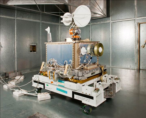
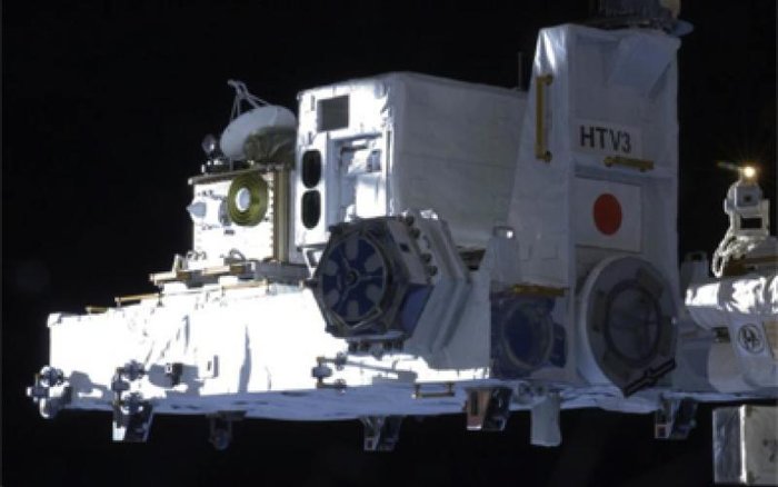
Sensonor AS is partnering with NASA to supply current and future low- and near-Earth orbit space missions with inertial and gyroscope modules.
The Norway-based company first began supplying its standard inertial measurement unit (IMU) and gyroscope modules for low Earth orbit (LEO) space applications in 2012, beginning with the launch of the NASA-sponsored AeroCube-4 satellite. Sensonor’s STIM300 and STIM210 inertial products are now a standard part in many spacecraft similar to the AeroCube-4.
Current NASA projects using STIM inertial systems include the Raven technology demonstration and Near Earth Asteroid (NEA) Scout.
Raven, which launches to the International Space Station in September, will test key elements of an autonomous relative navigation system. Its technologies may one day help future robotic spacecraft autonomously and seamlessly rendezvous with other objects in motion, such as a satellite in need of fuel or a tumbling asteroid.
The concept image above shows the NEA Scout CubeSat with its solar sail deployed as it characterizes a near-Earth asteroid. (NASA)
The NEA Scout is a robotic reconnaissance mission that will be deployed to fly by and return data from an asteroid representative of NEAs.
NASA, in conjunction with the Aerospace Corp., spearheaded the use of STIM products in space, and many other commercial launch and satellite companies have since followed NASA’s lead. In fact, more than 30 companies around the world use Sensonor inertial products in various space applications, with several satellites successfully flying with STIM gyroscope modules for over three years.
The STIM gyroscope modules are often used in combination with GPS or a Star Tracker and Kalman Filter to orient and stabilize the satellite, as well as to provide feedback on satellite motion induced by its reaction wheels. In some applications, the gyroscopes are used to stabilize satellite- to-satellite communications.
Being a supplier illustrates the trust NASA and others place in Sensonor, further solidifying the company’s role in this market. “We look forward to continuing to serve the international space community with our inertial offerings as standard commercial off-the-shelf (COTS) products. By serving the space market on equal terms with our other customers, we can help to reduce the cost of manufacturing and launching space payloads,” said Hans-Richard Petersen, Sensonor’s vice president of sales and marketing. “Our STIM products are the lowest size, weight, and power for their performance level in the market, with 5 to 10 times lower weight than the next-best alternative with similar performance. This makes them a very cost-effective and attractive solution.”
Sensonor will continue to improve its gyroscope module and IMU product performance and features, and is actively working with the space community to enhance its standard commercial-off-the-shelf (COTS) parts. Following the tremendous interest from the space community, Sensonor has initiated a space-optimized version of its STIM gyro module.
Featuring an exclusive interview with Astronaut Scott Kelly from aboard the International Space Station
This month, we discuss sailplanes of all sorts and conduct a brief on-orbit interview with Astronaut Scott Kelly concerning his time piloting the space shuttle — actually a supersonic glider. We touch on the role GPS played in making it a safer rocket glider. Kelly also gives us an update on his time aboard the International Space Station (ISS), nine months and counting.
When you think of gliders — or more accurately sailplanes — you probably think of long flexible wings, slow flight, bubble canopies, pristine white aircraft gleaming in the sunlight and tow requirements. For most aviators, the holiday picture of the beautiful Schleicher Model 32 sailplane below typically comes to mind.
AS (Schleicher) Model 32. (Courtesy of AS GMBH)
However, there are certainly some World War II combat glider pilots living today, heroes all, although unfortunately fewer and fewer everyday, that think of gliders in a very different way. They think of and remember huge green, tan and camouflaged wooden and cloth flying machines that carried 10 or more troops, who — if they lived through the experience — were able to wear glider rather than paratroop badges.
Army General William C. Westmoreland said of the heroic combat glider aviators, “Every landing was a genuine do-or-die situation . . . it was their awesome responsibility to repeatedly risk their lives by landing in unfamiliar fields deep within enemy-held territory, often in total darkness. They were the only aviators during World War II who had no motors, no parachutes, and no second chances.”
Graphic: Glider Pilot’s Wings from WWII.
Graphic: Glider Infantry Badge WWII.
The venerable wooden and cloth combat gliders of World War II were about as far removed from soaring sailplanes as a glider can be. Once released, they glided or, more accurately, careened to Earth. They were versatile and rugged enough to carry combat vehicles behind enemy lines and land in rugged terrain. but they most certainly did not soar.
The courageous flight crews did not have the luxury of GPS. Navigating for the short time after the tow vehicle — typically a transport, cargo (C-24) or bomber aircraft (like the B-24) — dropped them off at altitude, almost always below 10,000 feet, was a very hit or miss affair. There were only four very basic flight instruments on the glider’s rudimentary control panel, which most of the pilots completely mistrusted and ignored.
Glider flying in World War II was strictly VFR, or visual flight rules. Veteran glider pilots tell me that finding your landing zone (notice I did not say runway) was frequently haphazard. Often they had to make do with any decent-sized farmer’s field as a landing zone. Frequently, these landing were made in broad daylight, behind enemy lines, amid a hail of bullets, so they were fraught with danger in many ways, including not knowing their exact location when they finally landed. Glider infantrymen and glider pilot casualties reached 40 percent for some missions. What would they have given for a GPS?
The venerable WACO gliders were the most common versions. By war’s end, more than 13,900 CG-4A gliders had rolled off the production lines of several companies mass producing the same design for approximately $15,000 per copy — although one company charged as much as $50,000 per unit. It is estimated that less than one tenth of 1 percent of the gliders survived to fly after conflict ceased in 1945.
According to the Silver Wings National World War II Glider Pilots Association, “Over 6,000 individuals were trained as combat glider pilots and earned their silver wings with MOS (military operational specialty) 1026. Approximately 150 glider pilots and Troop Carrier Veterans still participate in the group’s activities, although their numbers are declining with ages in the 89- to 96-year group.
Author Michael MacRae, writing on the ASME (American Society of Mechanical Engineers) webpage in an article titled “The Flying Coffins of WWII,” describes the WACO CG-4A as America’s first stealth aircraft, but also as an aircraft expendable by design: “The CG-4A fuselage was 48 feet long and constructed of steel tubing and canvas skin. Its honeycombed plywood floor could support more than 4,000 pounds, approximately the glider’s own empty weight. It could carry two pilots and up to 13 troops, or a combination of heavy equipment and small crews to operate it. The nose section could swing up to create a 5 x 6-foot cargo door for Jeeps, 75-mm howitzers, or similarly sized vehicle. With a wingspan of 83.5 feet, the Waco maxed out at 150 mph when connected to its tow plane. Once the 300-foot length of 1-inch nylon rope was cut, typical gliding speed was 72 mph.”
Gliders first appeared in U.S. combat operations in the 1943 invasion of Sicily. They flew on D-Day into Normandy, June 6, 1944, and in other important airborne operations in Europe such as Operation Market Garden, the Battle of the Bulge, and crossing the Rhine, as well as in the China-Burma-India Theater.
After World War II, the gliders participated in U.S. military exercises in 1949, but glider operations were deleted from the U.S. Army’s capabilities on Jan. 1, 1953. Today, only special forces use gliders for silent, small-scale insertion.
Sailplanes
In contrast, a modern-day open competition glider built by the world-famous Alexander Schleicher (AS) company, for example, can soar to more than 50,000 feet with a supplemental oxygen supply, cruise at 280 kph or 170+ mph with a glide ratio of up to 80:1, with flight durations lasting more than 50 hours. Most modern sailplanes today fully incorporate GPS into their avionics suite that rivals any powered aircraft cockpit.
Contrast this with the World War II combat gliders that careened Earthward with somewhere between a 16 to 30:1 glide ratio at 70+ mph on a trajectory that typically lasted 10-15 minutes max. Sad to say, most of the operational versus training flights during World War II were one-time affairs and one-way trips, but they delivered the goods, including some very expensive firewood once the gliders were abandoned. Certainly, the WACO CG-4A glider was the last of its genre. Mothballed at war’s end, fewer than a dozen restored gliders exist today.
Rocket Gliders
Now to the heart of the matter. Gliders have evolved in ways that are difficult to imagine. Many of the aircraft that have broken world altitude and speed records are actually gliders, although we don’t typically think of them as being among that genre.
Messerschmitt Me 163B at the National Museum of the United States Air Force. (U.S. Air Force photo)
Typically a rocket-powered glider consumes fuel at a rapid rate, so most glide in for a landing. Examples include the German Messerschmitt Me 163 rocket-powered interceptor seen above, as well as the American series of research aircraft starting with the Bell X-1, which first flew and glided in for an unpowered landing in 1946. Examples of the type include the North American X-15, which spent much more time flying unpowered than under power.
In the 1960s, research and development or test vehicles now known as unpowered lifting bodies such as the X-20 Dyna-Soar space project vehicle were all the rage, and even though the X20 was eventually cancelled, the R&D led directly to the development of the U.S. space shuttle.
U.S. space shuttles: The world’s highest flying and fastest manned gliders
NASA’s now-famous and retired space shuttle first flew on April 12, 1981. The shuttle, which was a powered rocket during liftoff and cruise, re-entered as the fastest glider known to man at Mach 25 at the end of each spaceflight, landing entirely as an unpowered glider that, ironically, created its own sonic boom when it re-entered the atmosphere.
The U.S. space shuttle and its Soviet equivalent, the seldom-seen Buran shuttle, were by far the fastest aircraft ever to fly and, by a wide margin, the fastest gliders ever to fly in space and in the atmosphere.
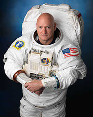
NASA astronaut Scott Kelly floats aboard the International Space Station after the hatch opening of the Soyuz spacecraft Mar. 28, 2015. (Photo: NASA)
One of the more well known space shuttle command pilots is Commander Scott Kelly, who as I write this is well into his ninth month aboard the International Space Station (ISS). He has three more long months to go before he returns home to a hero’s welcome and a battery of medical tests to determine how longevity in space affects the human body by comparing him to his astronaut twin who remained Earth-side during the same 12-month period. You know Einstein’s general theory of relativity, divided by telomere length and all sorts of quantum mechanics and medical technology. Talk about being poked and prodded.
Scott Joseph Kelly (born Feb. 21, 1964) is an American astronaut, engineer and a retired U.S. Navy Captain. A veteran of three previous missions, Kelly was selected in November 2012 for a special year-long mission to the International Space Station, which began in March 2015.
Scott Kelly is interesting for one more record he created during his time as a shuttle commander and shuttle command pilot. He flew the first-ever space shuttle GPS approach on Aug. 21, 2007, on STS-118. When I first heard about this feat, I thought it would be interesting to talk with Scott about it, and I made plans to do so upon his return from the ISS in March 2016.
However, through the marvels of instant messaging and the good graces of my friend Joe Rolli at Harris Corporation (nee Exelis, nee ITT) I was put in touch with Scott Kelly.
We conducted our brief interview electronically with nary a glitch even though Scott is hurtling around the Earth in low Earth orbit at a speed of approximately 17,150 miles per hour (about 5 miles per second). This means that as Scott orbits the Earth, he experiences a sunrise once every 92 minutes for a total of 5,634 sunrise events during his year on orbit.
Relatively, however, compared with the speed of electrons or light, which travel at 670,616,629.4 mph in the vacuum of space, Scott and I — who are traveling at a differential of 17 orders of magnitude compared to electrons — are essentially standing still. So the seemingly huge speed differentials makes little or no difference. Again Einstein, Newton, Schroedinger and probably his cat, if alive, would beg to differ on a technicality, but for our intents and purposes, I stick by my statement.
Here’s how that interview went. I want to publicly thank Scott for taking the time out of an incredibly busy schedule to talk with us about the importance of GPS and the space shuttle. Scott currently serves as Commander of the ISS on the one-year mission. In October 2015, he set the record for the total amount of days spent in space by an American astronaut — 382. As this article goes to press, Scott has spent more than 445 days in space.
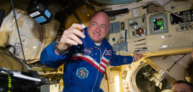
NASA astronaut Scott Kelly has been aboard the International Space Station since March as part of an endurance mission to test the effects of long-term exposure to space. In this July 12, 2015, photo he poses for a selfie in the “Cupola” of the ISS. (Photo: NASA)
(Don: Don Jewell, GPS World Defense Editor; Scott: Astronaut Scott Kelly)
Don: Scott, thanks for taking the time out of your busy schedule for our questions concerning GPS and the first space shuttle approach made using that technology, which you flew several years ago now.
Scott: This was eight years ago and I don’t have notes here, so this is my best quick effort.
Don: Why did NASA decide to approve GPS approaches for the space shuttle, and why were you chosen to fly the first one? I would assume that your experience, safety, approach options and flexibility would play a part here.
Scott: TACAN was going away. I wasn’t assigned to STS-118 because of this. This was a secondary DTO or Developmental Test Objective.
Don: Was a GPS approach after that first landing always an option?
Scott: GPS approach is kind of a misnomer. We incorporated GPS into the navigation state [for the space shuttle] from about Mach 5 [five times the speed of sound] until we transitioned to a microwave landing system on final.
Don: Were the certified and validated GPS approaches unique, or did they mimic current approaches such as ILS or VOR/DME?
Scott: Actually, Don, they have little to do with the GPS approaches aircraft fly.
Don: Were there both precision and non-precision GPS approaches? Do you remember the approach speeds and critical points in the approach? Can you discuss them? Since some of the alternates around the globe are in fairly primitive locations, did GPS make them more accessible and actually provide more alternates?
Scott: Again, GPS was used to update our navigation state. On an approach to a runway without an MLS (Microwave Landing System), GPS would have been our primary navigation source to the ground, but its not like we would be looking at an approach plate.
Don: What were the minimums for a GPS approach, before you could start a descent profile for a GPS (aided) approach and landing?
Scott: Actually, Don, our weather minimums were pretty restricted before we could start the de-orbit burn [while still in orbit]. Ceilings of 5,000 feet I think.
Don: At what point in your descent profile were you or NASA required to make a decision about your landing location and alternates? And, related to that, was there a typical point during the descent profile where you were committed to a landing location and could not choose an alternate? How far was that from your landing site nominally?
Scott: Legally you could re-designate after the de-orbit burn to an alternate [landing] site, but this would be in a very critical situation and was never done. Basically, when we did the de-orbit burn, we were essentially committed to landing at the chosen airfield.
Don: In an emergency, were you able or authorized to land at an alternate that did not have an advance NASA team in place, and were you able to fly the space shuttle totally manually or were computers always involved for stability?
Scott: Yes, and computers were always involved.
Don: Many modern fighters are inherently unstable. When the last computer fails, ejection is the only option. How did this apply to the space shuttle?
Scott: We were [essentially] fly by wire…the shuttle can’t fly without at least the backup flight control system (FCS) computer. Nominally, we have four FCS computers online.
Don: Since aerodynamically you were essentially flying the world’s fastest and highest flying glider, at what point were you committed to a landing site? What discretion as the Pilot in Command did you have, or was it all up to NASA headquarters?
Scott: When you did the de-orbit burn, you were committed to a landing attempt somewhere. If you had communications with the Mission Control Center (MCC), they decided where you would land. [With] no communications, it is up to the commander in an emergency.
Don: The space shuttle exceeded the speed of sound by a factor of 25 in the Earth’s atmosphere (Mach 25) on approach. What were the handling characteristics when this occurred? While there was obviously a sonic boom, where there any handling anomalies that required manual inputs from the pilot in command?
Scott: There was a little buffeting — sort of like running off the road in a pickup truck.
Don: Speaking of alternates, if your landing gear failed to deploy, or you had an indication that there was a gear malfunction, where you able to land on alternate surfaces such as grass or sand? Most importantly, in your opinion, would the shuttle and crew have survived a water (ocean or lake) landing? And were these alternate landing sites planned for or simulated to any high degree of fidelity?
Scott: The simple answer is you would try and bailout, but of course crash, if you had no choice.
Don: Finally, your comments. What was it like to pilot the space shuttle, and what did having a GPS approach available mean to you?
Scott: It was a privilege. GPS allowed us to continue to fly the space shuttle as legacy systems like TACAN were retired.
Don: Thank you so much for your time. If you have some comments concerning your current one-year experiment aboard the ISS, that would be great.
Scott: Sure, Don. I am currently a little over 270 days into my one-year flight aboard the ISS and going strong. Plus, to bring this all back to GPS, I can definitely say that GPS is working well on the International Space Station. We also have a Garmin GPS in the Soyuz, which we would break out in an emergency situation, and use a handheld satellite phone if we had an off-nominal landing, to tell people where we were.
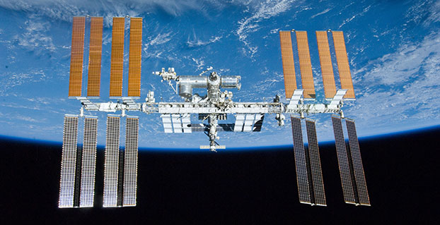
The International Space Station. (Photo: NASA)
Space Station and GPS
It is a good thing the GPS receivers on the ISS are working as well as they are. Since 2002, they have been the primary means for determining attitude, position, speed and universal coordinated time reference on the ISS. The GPS position of the ISS, which moves at five miles per second, is accurate to within 10 meters and is updated continuously.
Previously, according to NASA, the station’s position was determined using ground tracking and other techniques. That information was considered to be adequate if not overly accurate, as it was updated just once a day. Just before an update, the actual and propagated position of the station, the ephemeris, could differ by as much as 10,000 meters.
Specifically, the ISS uses the GPS position and velocity solution as the ISS navigation state. The ISS’s attitude determination filter combines the GPS receiver attitude information with ring laser gyro data available from the ISS rate gyro assembly (RGA) to produce the ISS attitude solution.
Today, continuous accurate knowledge of the space station’s location also keeps it safely out of the path of wayward space debris.
So now you know something about sailplanes, combat gliders, the U.S. space shuttle, the ISS, Astronaut Scott Kelly and how they are all affected by GPS. Even more importantly, I hope this column reinforces for you the ubiquity of the Global Positioning System.
GPS is the world’s time keeper and primary global time distribution system. GPS time synchronizes networks, computers, communications and any number of other devices, from Apple iWatches to undersea navigation, to systems used by private pilots, airlines, spacecraft and astronauts in deep space. You name it: If it uses time, chances are GPS time is the provider, with an incredible stability of 1E-14.
Indeed, you should think of GPS as an enabler. It enables so much of our technology today that it would be difficult to imagine living without it. Contrary to popular belief, even in the U.S. government, GPS is robust and reliable and becoming more so every day. Just think about it: GPS tells us when and where we are, how to get where we are going, and whether or not we are late. An amazing system, brought to you free of charge by the United States Air Force.
A new concept that involves mounting an instrument on the International Space Station and taking advantage of signals from navigation satellites could provide measurements of sea-surface height and information about features related to ocean currents, benefiting science and ocean forecasting.
We have all seen the beautiful photographs of our planet taken by astronauts, but orbiting Earth 16 times a day just 400 km above, the Space Station also offers a platform from which to measure certain variables related to climate change.
So, in 2011 the European Space Agency (ESA) called for proposals to explore how the Space Station could be used to make scientifically valid observations of Earth. After reviewing and assessing numerous proposals, the result is to further develop the GEROS-ISS mission concept.
Jason Hatton, GEROS-ISS project coordinator, said, “The concept is still going through feasibility studies, but the aim is to launch the experiment towards the end of 2019. It would be carried to the Space Station on a cargo vehicle and installed on ESA’s Columbus space laboratory using a robotic arm, after which GEROS-ISS would run for at least a year.”
GEROS-ISS stands for GNSS reflectometry, radio occultation and scatterometry on board the ISS. GPS and Galileo satellites send a continual stream of microwave signals to Earth for navigation purposes, but these signals also bounce off the surface and back into space.
The idea is to install an instrument with an antenna on the Space Station that would capture signals directly from these satellites as well as signals that are reflected or scattered from Earth. This process could be used to calculate the height of the sea surface, and to measure waves — or “roughness” — that can then be used to work out the speed of surface winds.
Variations in sea-surface height (cm) obtained by merging multiple altimeter measurements. GEROS-ISS would be able to observe this variability so that maps covering latitudes 51° N to 51° S can be produced every four days. (Photo: ESA)
GEROS-ISS is primarily an experiment to demonstrate new ways of observing Earth. However, if taken beyond the testing phase this new approach would complement measurements from satellites carrying altimeters such as CryoSat and Sentinel-3, and satellites carrying wind scatterometers such as MetOp.
Importantly, it is the first concept to assess the potential of spaceborne GNSS reflectometry to determine and map ocean height at scales of 10–100 km or longer in less than four days. Current satellite altimeters, in comparison, offer global maps at scales of around 80 km, which are produced from multiple datasets every 10 days.
A system based on GEROS-ISS would, therefore, complement existing satellite systems, helping to map ocean variability at finer spatial and temporal scales over a range of seas in tropical and temperate regions. It would also refine our understanding of how well the concept would work for measuring the roughness of the ocean surface.
In this respect, the development of GEROS-ISS benefits from experience gained with the UK’s TechDemoSat-1, which also measures ocean-surface roughness using a similar technique. It is also hoped that NASA’s upcoming CYGNSS constellation of mini satellites will help pave the way for GEROS-ISS.
In addition, GEROS-ISS uses a technique called radio occultation whereby the antenna receives signals that are refracted as they pass through the atmosphere. This can be used to generate vertical profiles of atmospheric humidity, pressure and temperature, as does the GRAS instrument on the MetOp satellites, for example.
GEROS-ISS will be installed on the upper balcony of ESA’s Columbus space laboratory, which provides mechanical interface plates as well as power, command and data links to the ISS systems. (Photo: ESA, taken by ESA astronaut Luca Parmitano during his spacewalk on July 9, 2013. )
“It is very flexible, combining different mission concepts and applications in one: GNSS-reflectometry to determine sea-surface height, scatterometry to measure sea-surface roughness and radio occultation for atmospheric studies,” said Jens Wickert who leads the science team that proposed GEROS-ISS.
ESA engineer Manuel Martin-Neira noted, “The original concept actually goes back over 20 years and has matured considerably through numerous studies and campaigns, however, it has never been duly tested from space.”
“Being able to use the International Space Station in this way means that we can quickly validate innovative observing techniques without having to build an entire satellite, and we expect this to lead to new opportunities for science,” added Michael Kern, ESA’s GEROS-ISS mission scientist.
The GEROS-ISS feasibility studies are being carried out through ESA’s General Studies Programme.
Editor’s Note:GPS World discussed the use of GPS for radio occultation in itsMarch 1994 Innovation column, “Monitoring the Earth’s Atmosphere with GPS,” by Rob Kursinski.