Tag: Japanese Quasi-Zenith Satellite System

  • Research Report: Advancing precision in navigation

    Research Report: Advancing precision in navigation

    Photo: Government of Japan
    Photo: Government of Japan

    In early 2015, the Navigation Support Office of the European Space Agency (ESA) and the Japan Aerospace Exploration Agency (JAXA) began a collaboration. At its core, the ESA-JAXA collaboration is designed to cross-validate Japan’s Quasi-Zenith Satellite System (QZSS) Precise Orbit Determination (POD) results and share expertise to improve the POD accuracy of QZSS.

    The cross-validation of the QZSS POD performance was implemented by jointly analyzing QZSS observations and validating the POD results of the QZSS satellites. As a result of this joint activity, ESA and JAXA have significantly improved the robustness and accuracy of their respective POD products. This collaborative approach not only ensures the continuous improvement of QZSS force modeling and precise orbit determination performance but also demonstrates the effectiveness of international cooperation in advancing the field of space navigation, especially as the benefits of GNSS interoperability become very evident.

    An important milestone in this collaboration was ESA’s role in supporting the In-Orbit Testing (IOT) activities for QZS-1R towards the end of 2021. The successful execution of these tests demonstrated the practical results of the ESA-JAXA partnership and further solidified the commitment of both agencies to enhance their capabilities for QZSS POD and associated products.

    FIGURE 1 ESA’s Solar Radiation Pressure (SRP) model output in satellite-Sun frame.
    FIGURE 1 ESA’s Solar Radiation Pressure (SRP) model output in satellite-Sun frame.

    The benefits of this collaboration extend beyond the agencies to the entire scientific community. Notable achievements include the revision of metadata for the QZSS constellation, such as the optical properties of the QZS-1 solar arrays, which have been refined and improved through shared expertise, while simultaneously releasing the satellite mass and attitude mode history in a machine-readable file format for easy access and adoption by the users.

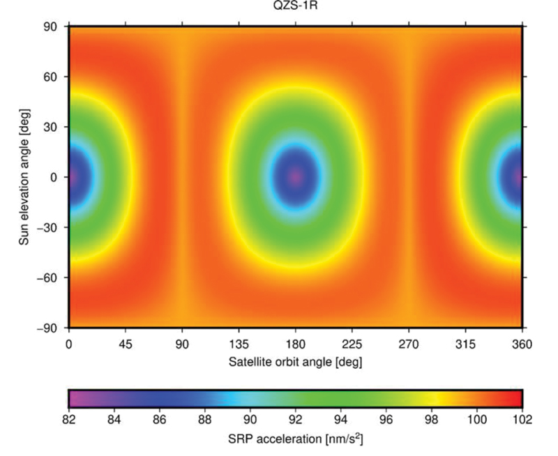
    To evaluate the spacecraft models and metadata for QZS-1R prior to their public release, ESA and JAXA conducted several comparative tests. Since both organizations use different software packages for satellite POD — ESA uses NAPEOS (Dow, Springer 2009, Enderle et al., 2019 and 2022) and JAXA uses MADOCA (Kawate et al., 2023) — their results can be considered as largely independent. One comparison involved the Solar Radiation Pressure (SRP) model results produced by both organizations. FIGURE 1 shows the accelerations in satellite-Sun frame computed by ESA’s SRP model. The comparison of the computed SRP accelerations in different reference frames, spacecraft-fixed and inertial, showed excellent agreement with differences of less than 0.1 nm/s².

    FIGURE 2 One-way Satellite Laser Ranging (SLR) range residuals calculated with respect to QZS- 1R orbits generated with (green) and without (blue) a-priori radiation force models and displayed as function of the Earth-Probe-Sun angle.
    FIGURE 2 One-way Satellite Laser Ranging (SLR) range residuals calculated with respect to QZS- 1R orbits generated with (green) and without (blue) a-priori radiation force models and displayed as function of the Earth-Probe-Sun angle.

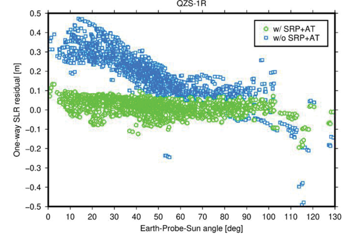
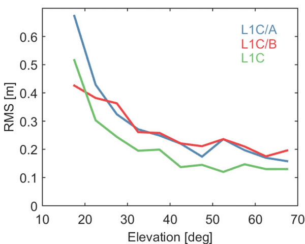
    In addition, pseudo-range and carrier phase dual-frequency measurement data from 200 tracking stations of the International GNSS Service (IGS) network were used to generate precise QZS-1R satellite orbits and clock offsets on a day-to-day basis over a 12-month period spanning from January to December 2022. Comparison between ESA and JAXA solutions yielded a root-mean-square (RMS) agreement of 8.6 centimeters (orbit) and 0.21 nanoseconds (clock), respectively. Analysis of Satellite Laser Ranging (SLR) data from seven stations of the International Laser Ranging Service (ILRS) suggests a radial RMS accuracy of the generated orbital trajectories of about 4 cm. Without applying the analytical models for SRP and other non-gravitational perturbation forces, such as antenna thrust (AT), the RMS accuracy decreases by a factor of five (FIGURE 2).

    In conclusion, the ESA-JAXA collaboration on Japanese Quasi-Zenith Satellite System POD has been a resounding success. Through this continuous and mutual support, performance cross-validation and knowledge sharing, significant improvements related to modeling and subsequently to POD accuracy could be achieved for ESA as well as for JAXA. Additionally, the global scientific community benefitted from this ESA/JAXA collaboration via improved QZSS POD products and validated metadata.


    Figure 1 and 2 courtesy of the authors

  • First transmission of L1C/B by QZS-1R

    First transmission of L1C/B by QZS-1R

    QZS-R1 is prepped for testing. At left is the Earth-oriented surface that hosts the L-band antenna. (Photo: JAXA)
    QZS-R1 is prepped for testing. At left is the Earth-oriented surface that hosts the L-band antenna. (Photo: JAXA)

    By Peter Steigenberger, Steffen Thoelert, Sergei Yudanov and Markus Ramatschi

    The Japanese QZS-1R satellite was launched on Oct. 26, 2021, from the Tanegashima Space Center in Japan. It serves as a replenishment for QZS-1, the first spacecraft of the Japanese Quasi-Zenith Satellite System (QZSS) in orbit since September 2010.

    QZS-1R joins the current QZSS constellation of three satellites in inclined geosynchronous orbit (IGSO) and one geostationary satellite. These four Block I satellites transmit the L1C/A signal at 1575.42 MHz.

    QZS-1R, as well as future QZSS satellites, are able to transmit the new L1C/B signal. L1C/B is based on the same family of gold codes as L1C/A, but uses a binary offset carrier (BOC) modulation instead of the binary phase-shift keying (BPSK) and a different PRN range (203–206).

    Compared to BPSK, the BOC modulation adds a square wave subcarrier with a frequency of fsc = 1.023 MHz that equals the chipping rate of the ranging code. This subcarrier shifts the peak spectral energy from the center frequency fL1 to fL1 ± fsc to reduce interference with the GPS L1C/A signals.

    During in-orbit testing (IOT) from late November until early December 2021, QZS-1R transmitted L1C/A and L1C/B signals intermittently. FIGURE 1 shows a spectrum of the L1-band transmissions of QZS-1R recorded on Nov. 25 with the 30-meter dish antenna of the German Space Operations Center in Weilheim, Germany, as well as a spectrum of QZS-2 recorded in July 2017.

    Figure 1. L1 spectra of QZS-1R (red) transmitting L1C/B and L1C, as well as QZS-2 (blue) transmitting L1C/A and L1C. The spectra were measured with DLR’s 30-meter high-gain antenna on Nov. 25, 2021, and July 20, 2017, respectively. (Credit: DLR)
    Figure 1. L1 spectra of QZS-1R (red) transmitting L1C/B and L1C, as well as QZS-2 (blue) transmitting L1C/A and L1C. The spectra were measured with DLR’s 30-meter high-gain antenna on Nov. 25, 2021, and July 20, 2017, respectively. (Credit: DLR)

    During IOT, QZS-1R had an extremely low maximum elevation of 0.8° in Weilheim. Due to technical restrictions for such low elevations, QZS-1R had to be observed with a sidelobe of the 30-meter antenna. As a result, the respective observations are much more noisy than the QZS-2 reference data.

    Nevertheless, the different spectral characteristics of L1C/B and L1C/A can be clearly seen in FIGURE 1: L1C/B has two maxima at 1574.4 and 1576.5 MHz due to the BOC modulation, whereas the BPSK L1C/A signal has one maximum at the center frequency of 1575.42 MHz.

    GNSS receivers of the International GNSS Service (IGS) started to track L1C/A, L1C, L2C and L5 signals of QZS-1R on Nov. 17. Aside from the regular PRN code J04, test signals using the non-standard code PRN J06 were intermittently transmitted by QZS-1R during the IOT and tracked by these receivers.

    Based on the public specification of the new L1C/B signal, Javad GNSS developed a prototype firmware that enabled tracking of this signal during the early transmissions. This firmware was installed on a Javad TRE-3 receiver operated by GFZ German Research Centre for Geosciences at its IGS station WUH200CHN in Wuhan, China.

    FIGURE 2 illustrates the noise and multipath characteristics of different QZS-1R pseudorange measurements. It is based on the so-called multipath linear combination of L1 pseudorange and L1/L2 carrier-phase observations covering a six-hour data arc. RMS values were computed for 5-degree elevation bins for each pseudorange signal. While the individual signals were tracked on different days of the IOT and the associated results have to be interpreted with care, the data indicate a very similar ranging performance of the legacy C/A signal and the new C/B signal. Best results are obtained with the L1C signal, which uses both a higher signal power and an advanced modulation with superior multipath suppression.

    Figure 2. Noise and multipath characteristics of QZS-1R signals on the L1 frequency tracked by the IGS station WUH200CHN in Wuhan, China. (Credit: DLR)
    Figure 2. Noise and multipath characteristics of QZS-1R signals on the L1 frequency tracked by the IGS station WUH200CHN in Wuhan, China. (Credit: DLR)

    QZS-1R will resume continuous transmission of L1C/A as soon as declared healthy. The transition from L1C/A to L1C/B is planned for 2023-2024, when an operational QZSS constellation of seven satellites is reached. The launches of the IGSO satellite QZS-5, the geostationary QZS-6, and the quasi-geostationary QZS-7 are all planned for 2023.

    Also see Directions 2022: Now 3 years old, QZSS hits its stride.

    Manufacturers

    GNSS data used in this article were collected with a Javad GNSS TRE-3 receiver. The spectral overviews were captured with a Rohde & Schwarz FSQ26 signal analyzer.


    Peter Steigenberger is a senior scientist at the German Space Operations Center of the German Aerospace Center (DLR), where he conducts research in the field of new satellite navigation systems.

    Steffen Thoelert is an electrical engineer at DLR’s Institute of Communications and Navigation. His research activities focus on signal-quality monitoring and satellite payload characterization.

    Sergei Yudanov is a senior firmware developer at Javad GNSS, Moscow. His main field of activity is GNSS signal processing.

    Markus Ramatschi is a senior scientist at the Helmholtz Centre Potsdam, GFZ German Research Centre for Geoscience. He is operating a global GNSS reference station network.


    Further Reading

    Cabinet Office, Quasi-Zenith Satellite System Interface Specification: Satellite Positioning, Navigation and Timing Service, IS-QZSS-PNT-004, Jan. 25, 2021.

    Ramatschi M., Bradke M., Nischan T., Männel B. (2019): “GNSS data of the global GFZ tracking network,” vol 1. GFZ Data Services. https://doi.org/10.5880/GFZ.1.1.2020.001

    Thoelert S., Hauschild A., Steigenberger P., Montenbruck O., Langley R. (2017), “QZS-2 signal analysis, QZS-3 launched.” GPS World 28(9): 10–14,

  • Japan’s QZSS constellation to receive replacement satellite

    Japan’s QZSS constellation to receive replacement satellite

    The successor to the first quasi-zenith satellite, dubbed Michibiki, is expected to launch this year.

    Michibiki was launched by the Japan Aerospace Exploration Agency (JAXA) in September 2010 and was transferred to the Cabinet Office in 2017. The replacement satellite is now undergoing prototype testing at the satellite manufacturer’s facility  (Mitsubishi Electric Co. Ltd. Kamakura Seisakusho) in Kanagawa. 

    The tests will confirm performance of the replacement satellite before it is put into service. It is undergoing acousitic, vibration and thermal vacuum tests to ensure it will remain functional after launch and in space. 

    After testing, the satellite will be transported to the Tanegashima Space Center for launch, which is expected to take place later this year.

    Replacement for Michibiki: The L-band antenna that transmits the positioning signal is mounted on the Earth-oriented left side. (Photo: JAXA)
    Replacement for Michibiki: The L-band antenna that transmits the positioning signal is mounted on the Earth-oriented left side. (Photo: JAXA)

    Though built to succeed the first QZSS satellite, the replacement is based on the second and fourth satellites

    Main specifications of the successor to the first satellite and other satellites:

    item First machine Units 2 and 4 Unit 3 Successor to the first machine
    Orbit Quasi-zenith Quasi-zenith Rest Quasi-zenith
    Positioning signal L1-C / A,
    L1C, L1S,
    L2C, L5, L6
    L1-C / A, L1C,
    L1S, L2C,
    L5, L5S, L6
    L1-C / A, L1C,
    L1S, L1Sb, L2C,
    L5, L5S, L6
    L1-C / A
    (L1-C / B (* 1)),
    L1C, L1S, L2C,
    L5, L5S, L6
    L band antenna Helical method
    (* 2)
    Helical method
    (* 2)
    Patch method
    (* 3)
    Patch method
    (* 3)
    Generated power 5.3kW 6.3kW 6.3kW 6.3kW
    mass About 4t About 4t About 4.7t About 4t
    Design life 10 years or more Over 15 years Over 15 years Over 15 years
    Launch year 2010 2017 2017 2021
    (planned)
    Launch
    rocket
    H2A202 H2A202 H2A204 H2A202
    (* 1) Signal transmitted by BOC (Binary Offset Carrier) modulation of L1-C / A code
    (* 2) Antenna with spiral antenna elements arranged
    (* 3) Antenna with planar antenna elements arranged

    .


  • QZSS satellites benefit Western Australia industries, study shows

    Curtin University researchers found the launch of new Japanese satellites has boosted satellite positioning capabilities in Western Australia (WA), offering huge potential benefits across numerous industries including mining, surveying and navigation.

    New research, published in the journal GPS Solutions, found signals from the recently launched Japanese QZSS satellites provide centimeter-level positioning accuracy, and thus significantly enhanced positioning capabilities in WA, thereby improving accuracy, reliability and availability.

    Lead researcher Professor Peter Teunissen, of Curtin’s School of Earth and Planetary Sciences, said these results will improve further when the QZSS signals are combined with those from other satellite systems such as the Indian NavIC system.

    Teunissen said the analyses done by Curtin’s GNSS Research Centre demonstrated the highly accurate centimeter-level positioning capabilities that can now be achieved.

    “Such improved positioning, accuracy and reliability would offer great benefits when applied in fields such as open-pit mining, surveying, hydrography, automated navigation, structural health monitoring, and subsidence and tectonic deformation monitoring used in the geospatial industry,” Teunissen said. “The benefits are not only restricted to positioning, but cover the whole range of satellite signal applications, including atmospheric sensing (ionosphere and troposphere) as used for climate change and space weather studies, and numerical weather prediction.”

    Teunissen said WA was in the fortunate and unique geographical position of being located beneath the flight paths of both the Japanese QZSS and the Indian NavIC regional satellite systems.

    “Using both satellite systems, QZSS and NavIC, offers huge benefits to users in Australia – and this is an opportunity to work on future developments with such technologies,” Professor Teunissen said.

    “The United States of America, for example, can’t use these signals the way we can in Australia, so this places us in a position of great advantage when it comes to the understanding, modelling and analyses of these satellite signals and their many practical applications.

    “The tracking and analyses were done using Javad GNSS receivers and Curtin’s theory of integer ambiguity resolution, which enables millimeter-level satellite ranging, and was achieved with the use of only the four currently available QZSS satellites.”

    The results bode well for the future, with the Japanese system being further developed from the current four-satellite system into a mature seven-satellite system that is expected to be operational by 2020.

    The report, “Australia-First High-Precision Positioning Results with New Japanese QZSS Regional Satellite System, is available online.

  • Lighthouse front-end processes 4 GNSS frequencies simultaneously

    Lighthouse front-end processes 4 GNSS frequencies simultaneously

    Lighthouse Technology and Consulting Co. Ltd. has developed of a series of front-end processors for GNSS software receivers.

    The Hibiki processors can take input from up to four frequency GNSS signals simultaneously.

    The Hibiki front-end can process up to four GNSS signals for software receivers. (Image: Lighthouse)

    The Japanese Quasi-Zenith Satellite System (QZSS) broadcasts GNSS signals in four frequency bands: L1, L2, L5 and L6. Similarly, GPS and GLONASS broadcast in three bands, and the European Galileo and Chinese BeiDou systems broadcast in four bands.

    However, many conventional front-ends process only two bands at the same time, and cannot be used for highly specialized applications such as processing multiple signals with different frequencies at the same time.

    The Hibiki front-end processor was designed to answer to this GNSS technology demand and is able to process up to four frequency bands simultaneously, the company said.

    Hibiki has a high data transfer rate performance using USB 3.0, stably transmitting signal data to the host computer up to 50 million samples per second. This high sampling frequency is much greater than conventional front-end processors, improving L5 signal-receiving performance and reducing multipath.

    Hibiki is available starting in April.

    Chart: Lighthouse
    Chart: Lighthouse