By Peter Steigenberger, Steffen Thoelert, Oliver Montenbruck and Richard B. Langley
The first GPS III satellite, “Vespucci,” was launched in December 2018, started signal transmission in January 2020, and was set healthy later that month. The second GPS III satellite, nicknamed “Magellan,” was launched on Aug. 22, 2019, on a Delta IV rocket from Cape Canaveral, Florida.
Magellan, also identified by its space vehicle number (SVN) 75 (here referred to as GPS-75), started signal transmission with standard pseudorandom noise code (PRN) number 18 (here referred to as G18) on March 13. The L1 C/A, L1 P(Y), and L2 P(Y) signals were activated at 17:16:30 GPS Time (GPST), while the L1C, L2C and L5 signals followed less than two hours after Vespucci’s launch at 18:59:30 GPST. Transmission of navigation messages started at 19:00:00 GPST with GPS-75 (G18) marked as unhealthy.
PRN G18 was previously used by the 27-year-old Block IIA satellite GPS-34 that had been already removed from the active GPS constellation on Oct. 7, 2019, but continued signal transmission until March 9, 2020. GPS-75 is already being tracked by a large number of tracking stations of the International GNSS Service (IGS). Based on the data collected by these stations, the Center for Orbit Determination in Europe (CODE), headquartered in Bern, Switzerland, has been providing precise orbit and clock products for this satellite since March 14.
A comparison we performed with the CODE precise orbit products revealed initial broadcast ephemeris errors of up to 100 meters (3D) and an orbit-related signal-in-space range error (SISRE) of about 13 meters. Within four days, a SISRE (orbit component) of 24 centimeters was achieved, which closely matches the performance of the rest of the GPS constellation.
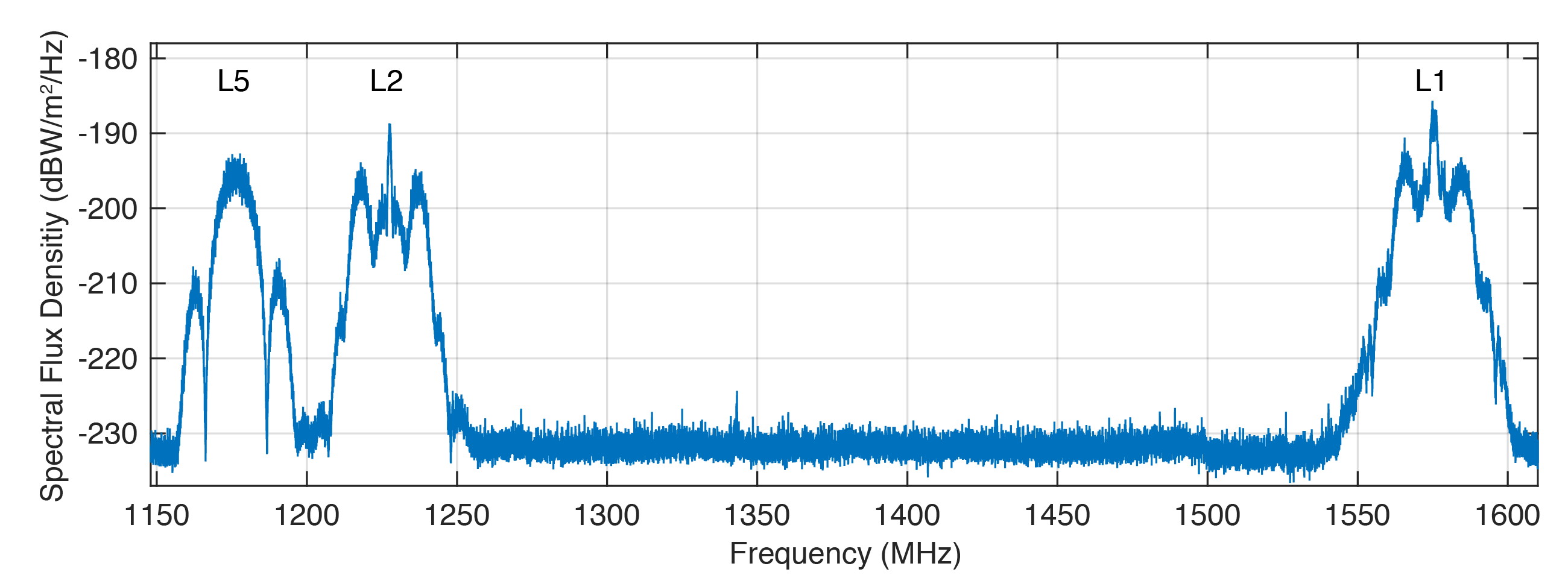
Figure 1 shows the spectral flux density of GPS-75 in the L1, L2 and L5 frequency bands obtained with the 30-meter high-gain antenna of the German Aerospace Center (DLR) located in Weilheim, Germany. The civil L1 C/A, L1C and L2C signals can be identified as sharp peaks in the center of the respective frequency bands.
FIGURE 1. Spectral flux density of GPS-75 measured with DLR’s 30-meter high-gain antenna. (Figure: Steigenberger, et al)
The prominent side lobes in the L1 and L2 bands are associated with the military M-code. The wide main lobe of the L5 signal with two smaller and sharper side lobes is caused by the superposition of two in-phase and quadrature signals with a 10-MHz binary phase-shift keying (BPSK) modulation. We found that all signals are in good shape and have a quality similar to that of the first GPS III satellite.
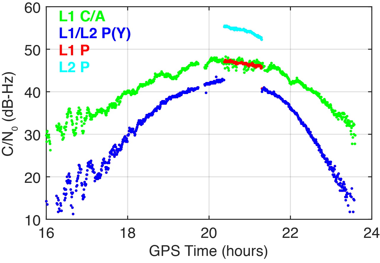
On March 16, 2020, we detected a significant change in the carrier-to-noise-density ratio of the L1 and L2 P(Y)-code signals. Figure 2 illustrates these changes for the IGS station located in Patumwan, Thailand (CUSV00THA). The L1 and L2 P-code signals are usually encrypted with the W-code to prevent spoofing (the generation of fake signals by adverse parties). The resulting encrypted signals are denoted by P(Y). Geodetic GNSS receivers are capable of tracking the P(Y) signals with a semi-codeless approach.
FIGURE 2. Carrier-to-noise-density ratio (C/N0) of the second GPS III satellite, GPS-75, tracked by the IGS station CUSV00THA in Patumwan, Thailand, on March 16, 2020. Between 20:22 and 21:18 GPST, unencrypted P-code signals were tracked. (Figure: Steigenberger, et al)
As a result, C/N0 of L1 P(Y) and L2 P(Y) are virtually identical and significantly smaller than the C/N0 of the unencrypted signals due to losses of the semi-codeless tracking technique. This can be seen in the blue-colored plot of Figure 2, where the C/N0 values of L1 P(Y) and L2 P(Y) are identical and smaller by 4.5–16 dB compared to L1 C/A depending on the elevation angle of the satellite.
However, between 20:22 and 21:18 GPST, an increase of the P-code C/N0 values was observed. The values changed by 4.5 and 12.5 dB for L1 and L2, respectively. This change is an indicator that unencrypted P-code signals were transmitted, rather than encrypted ones. This assumption can be verified by the “Anti-Spoof Flag” given as the 19th bit of the handover word (HOW) of the GPS LNAV navigation message.
Indeed, decoding of the raw navigation data from the IGS station CHOF00JPN in Chofu, Japan, showed that the Anti-Spoof Flag indicated a deactivation of anti-spoofing between 20:22:00 and 21:17:48 GPST and verified our assumption that unencrypted P-code signals were transmitted during that time period.
It has to be noted that only Javad receivers within the global multi-GNSS network of the IGS show this increase in C/N0. Other receiver types report continuous C/N0 values for the P-code signals, indicating that a semi-codeless tracking technique was continuously applied irrespective of the Anti-Spoof Flag.
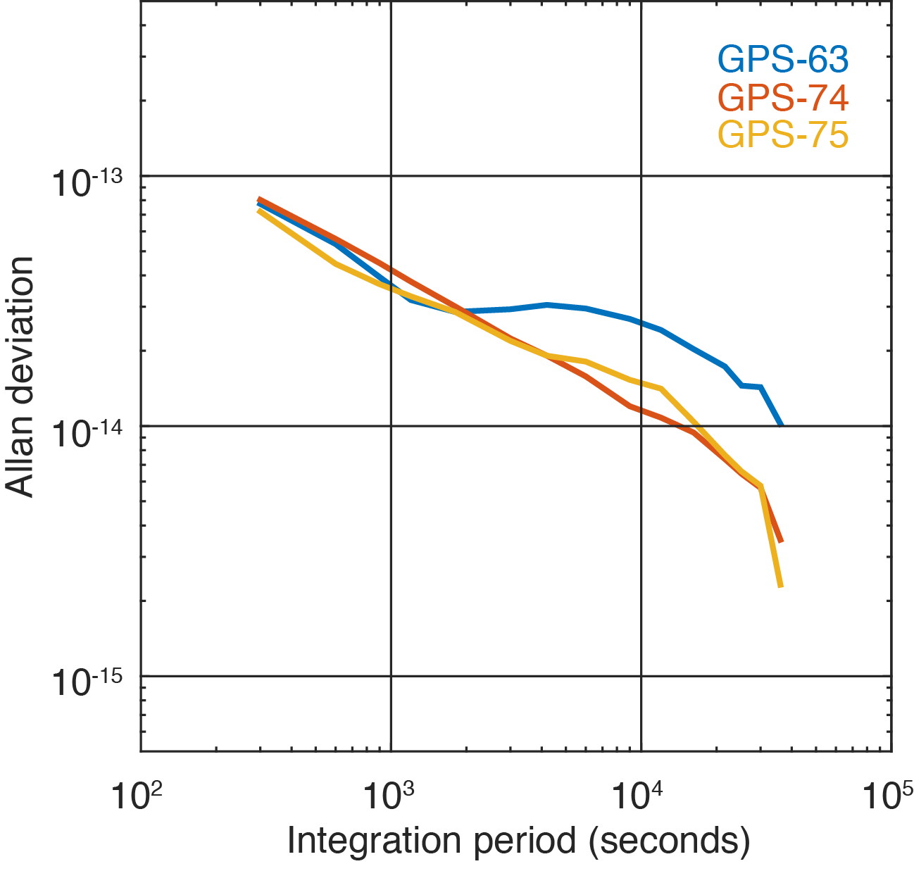
Figure 3 shows the two GPS III satellites’ Allan deviation, which measures the clock stability achieved in orbit; that is, the average frequency error over different time scales. In addition, the Block IIF satellite GPS-63 is shown, which is in the same orbital plane as GPS-75.
FIGURE 3. Allan deviation of the Block IIF satellite GPS-63 and the GPS III satellites GPS-74 and GPS-75 computed from 5-minute clock solutions produced by DLR. (Figure: Steigenberger, et al)
For integration times up to 2,000 seconds, the clock stability of GPS-75 is slightly better compared to the first GPS III satellite, GPS-74, but the situation is opposite for integration times larger than 5,000 seconds. The latter finding might be caused by the fact that GPS-75, unhealthy at the time, was tracked by a smaller number of stations compared to the healthy GPS-74.
As a consequence, the observed Allan deviation may partly be contaminated by orbit determination errors. In any case, both GPS III satellites clearly outperform the Block IIF satellite GPS-63 that suffers from thermal line bias variations visible as an increased Allan deviation starting at an integration time of about 2,000 seconds.
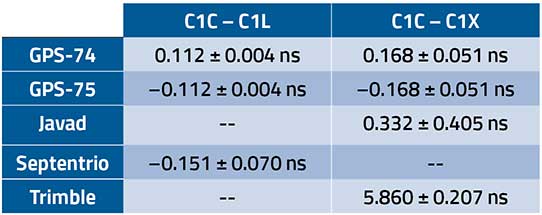
The activation of the second GPS III satellite transmitting the new civil L1C signal enables the estimation of differential code biases (DCBs) between, for example, the L1 C/A signal (Receiver Independent Exchange [RINEX] format observation code C1C) and different tracking modes of the L1C signal. Septentrio receivers track only the pilot component of the L1C signal (C1L), whereas Javad and Trimble receivers perform a combined data+pilot tracking (C1X).
DCBs are estimated from pseudorange (code) observations of a global tracking network and are corrected for ionospheric delays obtained from global ionosphere maps. The DCB estimates shown in Table 1 are based on eight days of data from 10 Javad, 21 Septentrio and 3 Trimble receivers.
TABLE 1. Differential code bias estimates in nanoseconds between L1 C/A and L1C for the GPS III satellites and average receiver DCBs. (Data: Steigenberger, et al)
As we have applied a zero-sum condition for the estimation of satellite DCBs of just two satellites, the values of GPS-74 and GPS-75 obtained from the same type of L1C observables differ only by the sign. The DCBs estimated from different L1C observables, namely C1L and C1X, differ by 56 picoseconds, corresponding to a range difference of 1.7 centimeters. The receiver DCBs are quite homogeneous for receivers from each manufacturer but differ by up to 6 nanoseconds between various manufacturers.
On April 1, 2020, GPS-75 was set healthy and joined the constellation of operational GPS satellites. The third GPS III satellite, named “Columbus,” was shipped to the Cape Canaveral launch site in February 2020. Its launch is expected no earlier than June 30, 2020, and at least two GPS III launches per year are planned for the near future.
Equipment. Measurements reported in this article were collected with JAVAD GNSS TRE_G3TH and TRE_3, Septentrio PolaRx5 and Trimble Alloy multi-GNSS, multi-frequency receivers. The spectral overview was captured with a Rohde & Schwarz EM100 digital compact receiver.
PETER STEIGENBERGER and OLIVER MONTENBRUCK are scientists at the German Space Operations Center of the German Aerospace Center (DLR). STEFFEN THOELERT is an electrical engineer at DLR’s Institute of Communications and Navigation. RICHARD B. LANGLEY is a professor at the University of New Brunswick and editor of the “Innovation” column for GPS World magazine.
Further Reading
“Optimum Semicodeless Carrier-Phase Tracking of L2” by K.T. Woo in Navigation, Vol. 47, No. 2, 2000, pp. 82-99, doi: 10.1002/j.2161-4296.2000.tb00204.x.
Interface Specification IS-GPS-200K: NAVSTAR GPS Space Segment/User Segment Interfaces by Global Positioning Systems Directorate Systems Engineering & Integration, Los Angeles Air Force Base, El Segundo, California, March 4, 2019. Available online: https://www.gps.gov/technical/icwg/IS-GPS-200K.pdf
“Apparent Clock Variations of the Block IIF-1 (SVN62) GPS Satellite“ by O. Montenbruck, U. Hugentobler, E. Dach, P. Steigenberger and A. Hauschild in GPS Solutions, Vol. 16, No.3, 2012, pp. 303-313, doi: 10.1007/s10291-011-0232-x.
“Differential Code Bias Estimation Using Multi-GNSS Observations and Global Ionosphere Maps” by O. Montenbruck, A. Hauschild and P. Steigenberger in Navigation, 2014, Vol. 61, No. 3, 2014, pp. 191-201, doi: 10.1002/navi.64
A new GPS civilian signal is now available for use. The new signal is stronger, more accurate, more resilient to interference events, and interoperable with European Galileo system.
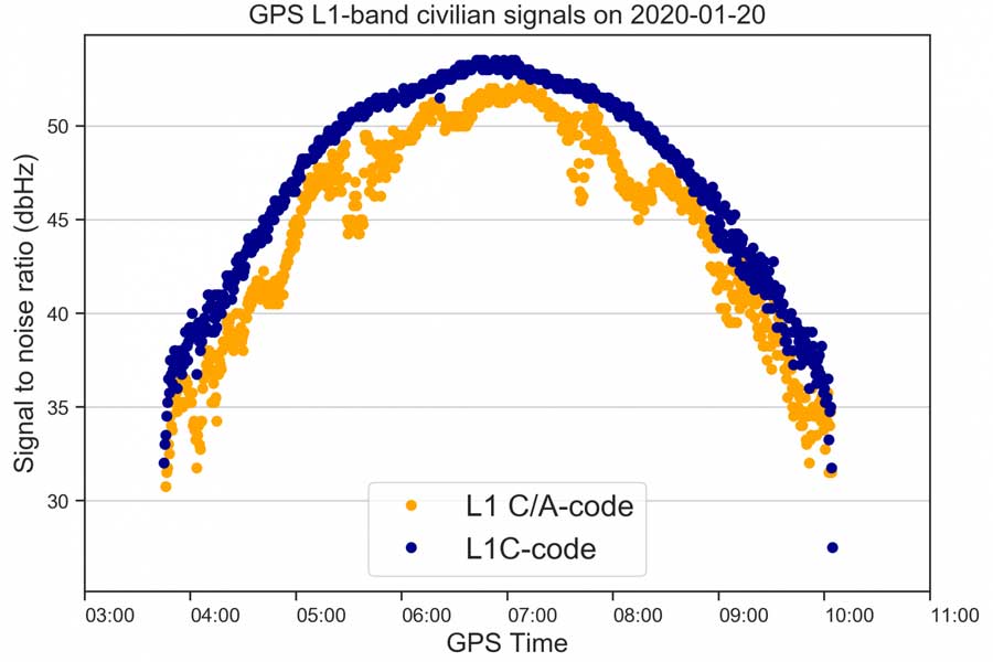
On Jan. 13 at 21:29 Finnish time, the first GPS III satellite (SVN74) was marked healthy after extensive operational testing in orbit. The satellite broadcasts PRN04 identification codes. It also transmits a new GPS civilian signal, known as L1C, different than the legacy L1 C/A signal used nowadays.
10 times longer
The two signals are transmitted at the same frequency, but L1C codes are 10 times longer than L1 C/A. This makes the signal more robust to interference when multiple satellites are tracked on the same frequency band.
“Marking a satellite health means receivers can use this satellite in their positioning, navigation and timing applications,” said Octavian Andrei, senior research scientist at the Finnish Geospatial Research Institute (FGI). “L1C is the 4th GPS signal for the civilian use.” The Finnish Geospatial Research Institute is a part of the National Land Survey of Finland.
The other three civilian signals of GPS are L2C, L5 and L1 C/A.
Interoperable with the European GNSS signalL1C signal is transmitted on L1-band at 1575.42 MHz. It is meant to replace the legacy C/A signal in the future. L1C allows for the first time GPS compatibility and full interoperability with signals from other satellite systems, such as E1 signal from the European Galileo.
The interoperability with Galileo is further enhanced by transmission of the inter-system timing biases; that is, the GPS-Galileo Time Offset. All these improvements will bring further benefits and developments to the GNSS market and civilian users in general.
Ionosphere no problem with dual-frequency
Andrei said the new signals means “Exciting times ahead for the civilian users and applications that demand precise satellite positioning and navigation. Most of the effects due to the ionosphere layers of the atmosphere are removed by combining signals from two frequency bands sufficiently apart from each other. This is the case with L1 and L2 or L1 and L5. All these civilian signals are stronger and more robust than ever before,” he explained.
The satellite signals are affected by errors while travelling through the atmosphere. The main errors are due to the ionosphere, which is a dispersive medium and frequency dependent. The latter proves to be actually a significant benefit for the precise applications.
The new signal (L1C, marked with blue) is 3-5 dBHz stronger and more robust than the legacy L1 C/A signal (marked with orange). (Image: Octavian Andrei)
More than 99 % of the ionosphere effect is removed by forming special linear combination of signals observed on two different frequencies. This is the main reason why high-precision is achieved with dual-frequency receivers.
FinnRef network ready for new satellites and signals
“Two GPS III satellites have been launched until now and two more are expected to be launched during 2020. With signals from four satellites, we will also be able to estimate L1C-only positions,” Andrei said.
The first GPS III satellite SVN74, nicknamed Vespucci, was launched on Dec. 23, 2018. The second satellite SVN75, nicknamed Magellan, was launched on Aug.22, 2019. The third and the fourth satellite are planned to be launched in March and July during 2020. The first L1C testing signals were recorded at the FinnRef station in Metsähovi on April 5, 2019.
FinnRef national network includes state-of-the-art multi-constellation tracking stations distributed around Finland. These stations are capable of tracking multiple satellite signals on multiple L-band frequencies from almost 120 GNSS satellites, including the European Union’s Galileo, US GPS, Russian GLONASS, and Chinese BeiDou constellation.
Using new signals often requires updates to station equipment, usually meaning firmware updates on the receiver software. After the new firmware enabling L1C tracking is properly tested, the receivers will be updated and then whole FinnRef will start tracking GPS L1C.
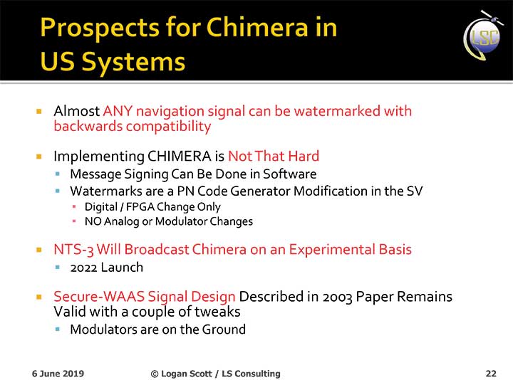
The U.S. Air Force will load a new signal feature, designed to make spoofing detectable, aboard a satellite that will broadcast it from space as a security overlay for the GPS L1C signal, but not until 2022 at the earliest.
The Chips Message Robust Authentication (Chimera) is now in testing under the auspices of the Air Force Research Laboratory (AFRL), getting ready to fly on the Navigation Technology Satellite 3 (NTS-3), which will trial a number of new PNT techniques and technologies.
Chimera inserts encrypted digital signatures and watermarks within the L1C signal. A GPS receiver with the requisite additional capability for this purpose can then detect whether the signal is real or fake and also authenticate the location of a GPS receiver that is remotely located.
This key feature could provide a defense against hacking by blocking access from anyone unable to prove they are at an anticipated or licensed site. Hacking, of course, is a growing threat to all sorts of infrastructure: financial, security, utility grid and more.
Presentation slide from PNT Advisory Board briefing by Logan Scott.
Consultant Logan Scott first proposed the Chimera technology in 2003, when he affirmed that “Some of the spoofing detection measures in wide use offer a false sense of security. Authenticatable signal architectures are needed.” In June, he made a presentation to the PNT Advisory Board: “The Role of Civil Signal Authentication in Trustable Systems.” The two slides accompanying this article appeared in that presentation.
“Chimera represents a fundamental paradigm shift in PVT security paradigms,” Scott related in a subsequent conversation. “Trust takes time and memory on a personal level and, in this case, in GNSS signals, too.
“You don’t trust somebody as soon as you meet them. Over a period of time, you get to know them. If you can’t remember anything, you can’t develop trust either.”
“In the GNSS world, there are a lot of applications where you don’t need output in real time,” Scott said. “For example, to align an inertial. The inertial provides the real-time aspect. You don’t want to send anything to the IMU that is factually incorrect. When building to aid inertial, I can afford to have a delay from real time as long as I tell it where it was 10 seconds ago. The power of that is, if I don’t have to give real-time output, I can ponder and think about things.
“If a spoofer attacks, there’s an evolution that happens there. If I, as the receiver, can see the developing scenario, and how it starts to look at little screwy, I can stop and not send anything to the IMU that might corrupt it.”
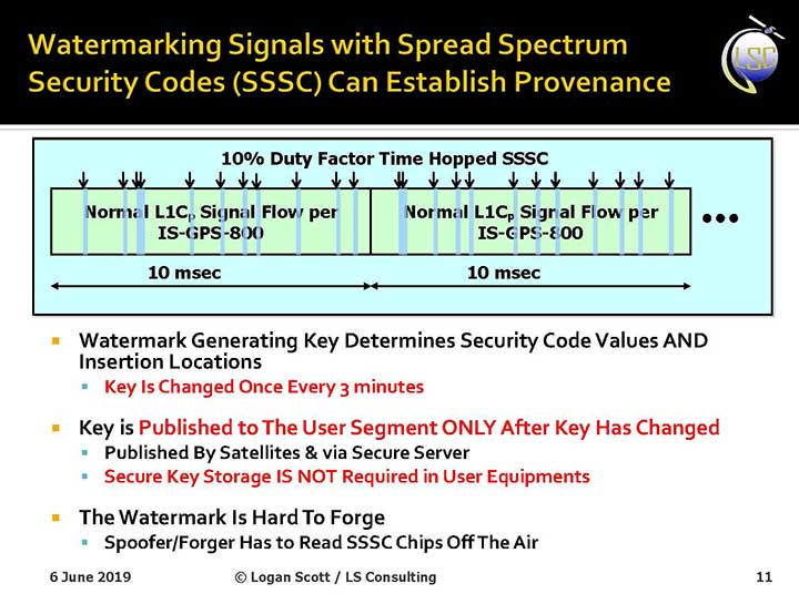
How It Works. The core concept of Chimera involves the satellites sending encrypted watermarks, encoded into the signal by the satellite. After a slight delay, the satellite sends the key used to generate those encrypted watermarks. Once a key is sent, the system changes the key.
Since the receiver has already recorded the signal with its watermarks before the key is sent, spoofers cannot know the correct key ahead of time, in time to insert correct watermarks of their own. This means that any spoofed signals can be easily spotted: either the subsequent key won’t match up with the spoofed watermarks, or there will be no watermarks at all.
“Another reason it’s hard for someone to generate these watermarks on their own is because the signal is buried below the noise,” added Scott. “The watermarks are hidden.”
A number of different time delays between signal and key are possible within this concept and within the general set-up of GPS. Scott and the AFRL have, for various practical reasons, provisionally settled on a 6-second delay on the fast watermark channel and a 3-minute delay for the slow watermark channel.
The signal enhancement could be incorporated into the Wide Area Augmentation System (WAAS). This has yet to be fully determined, but this route would lead to a faster implementation of Chimera. Scott thinks that going the WAAS route could bring Chimera capability into action within two years.
The AFRL, however, is looking at a much longer timeline. The NTS-3 satellite, where it first intends to test Chimera, will not launch until 2022 — three years hence. And that’s only a test, not an enactment or a system-wide implementation.
Slide: Logan Scott
Verification. One key benefit for commercial entities, particularly those in financial infrastructure and other systems that increasingly fall victim to hacking, is that Chimera gives them the ability to verify customers’ or partners’ locations before granting any kind of access. The customer’s or other erstwhile user’s GPS receiver would record the full signal, including the watermarks, and transmit that data to the company, entity or data center needing location verification, before the keys are published. Each combination of watermarks and signals is unique to the place where it was recorded, thus it is possible to tell whether the user is actually where they say they are, or in an authorized or pre-identified location before granting access or accepting further input (such as commands).
Scott claims that Chimera affords a 99.9% probability of detecting spoofers. “I have a 99.9% chance of detecting that the watermark is not there, because they don’t know how to generate it. This is based on how you’re processing the signal. It’s designed to be very flexible in how the receiver uses the signal.”
Just One Problem. Receiver manufacturers will have to develop new Chimera-capable receivers, and customers will have to buy them. An additional cost for the added processing, above and beyond that required for normal GPS operation, is unavoidable.
And a Hiccup. Chimera, while an acronym, is as a name perhaps not a totally felicitous choice. In Greek mythology, the chimera is a fire-breathing female monster with a lion’s head, a goat’s body, and a serpent’s tail. These historic ancestors have evolved into the word’s more current use: a thing that is hoped or wished for but that is in fact illusory or impossible to achieve.
AFRL Wants Your Opinion. The Air Force Research Laboratory seeks feedback from the PNT community on the Chimera enhancement for the L1C signal. The specification is here. And, you can download a comment form
Less than three weeks after its launch, the first GPS III satellite, SVN74, started transmitting navigation signals. SVN74 uses the pseudorandom noise (PRN) code number G04 previously used by the almost 25-year-old Block IIA satellite SVN36. The L1 C/A, L1 P(Y), and L2 P(Y) signals of SVN74 have been tracked since Jan. 9 at 00:01 UTC. Activation of the L2C and L5 signals followed on the same day at 19:43 UTC. Transmission of the legacy navigation message (LNAV) started Jan. 9, but the satellite is still marked unhealthy for ongoing on-orbit check out and testing.
Also, SVN74 is the first GPS satellite to transmit a new civil signal on the L1 frequency (1575.42 MHz), namely L1C, which was initially activated on the same day as the other SVN74 signals. Incidentally, the L1C signal was already being transmitted by the four satellites of the Japanese Quasi-Zenith Satellite System (QZSS).
Compared to the L1 C/A PRN codes, the L1C codes are 10 times longer (10,230 chips), reducing interference when multiple satellites are tracked by a receiver on the same frequency. Like L2C and L5, the L1C signal consists of a dataless pilot component and the data component with navigation data. Dataless signals enable more robust tracking under difficult conditions. For the L1C signal, 75 percent of its power is put into the pilot component.
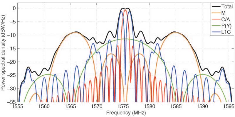
The theoretical spectra of the four signals transmitted on L1 by SVN74, namely the civil C/A-code and L1C, as well as the military P(Y)-code and M-code, are shown in FIGURE 1 along with the the total (summed) spectrum.
Figure 1. Theoretical spectra of the four signals transmitted by a GPS III satellite in the L1 frequency band. (Image: Authors)
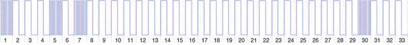
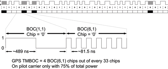
BOC. To achieve compatibility with the L1 C/A-code signal at the same center frequency, a binary offset carrier (BOC) modulation is used for spectral separation of L1C from L1 C/A. A BOC(n,m) signal is characterized by the fundamental frequency of the square wave subcarrier expressed in multiples n of the basic frequency of 1.023 MHz and the chipping rate expressed in multiples m of 1.023 megachips per second. A BOC(1,1) modulation is used for the L1C data component. For the pilot component, a time-multiplexed binary offset carrier (TMBOC) is used. The spreading waveform, with a length of 33 symbols, consists of four BOC(6,1) and 29 BOC(1,1) symbols as illustrated in FIGURE 2 resulting in a TMBOC(6,1,4/33) signal. The additional BOC(6,1) component allows for improved multipath mitigation.
Figure 2. Spreading symbols for the L1C pilot component: time-multiplexed BOC consisting of BOC(6,1) for the 1st, 5th, 7th and 30th symbols and BOC(1,1) for the other symbols. (Image: Authors)
Similar to GPS L1C, the European Galileo and the Chinese BeiDou-3 systems employ multiplexed BOC signals with BOC(1,1) and BOC(6,1) components in the L1 frequency band. A composite BOC (CBOC) modulation has been adopted for the Galileo E1 open service signal, which uses a weighted sum of the BOC(1,1) and BOC(6,1) components in both the data and the pilot channels. For the BeiDou B1C signal, BOC(1,1) is used for the data channel, while a quadrature multiplexed BOC modulation, QMBOC(6,1,4/33), with BOC(1,1) and BOC(6,1) subcarriers in phase quadrature, is used for the pilot channel.
Interoperability. The new civil L1 signals of GPS, Galileo and BeiDou show a high level of commonality and are specifically designed for full interoperability. This means that receivers can easily track signals of all three constellations and use the measurements to compute a combined multi-GNSS position solution. Aside from the similar signal modulations, the interoperability is further supported by the transmission of inter-system timing biases (such as the GPS-Galileo Time Offset) in the navigation messages.
The binary phase shift keying (BPSK) modulation of the C/A-code with a 1.023-MHz chipping rate introduces a main lobe at the center frequency of 1575.42 MHz and numerous side lobes with decreasing amplitude. The 10.23-MHz BPSK signal of the P(Y)-code is visible in Figure 1 as a broad peak at the center frequency and first side lobes at about 1560 and 1590 MHz. The M-code is characterized by its main lobes ±10.23 MHz from the center frequency due to its BOC(10,5) modulation. Finally, the L1C signal can be recognized as two narrow peaks separated by ±1.023 MHz from the L1 center frequency related to the BOC(1,1) modulation and two peaks at ±6.138 MHz related to the BOC(6,1) modulation. Side lobes of the BOC(1,1) signal are visible next to the main lobes at integer multiples of 2 × 1.023 MHz.
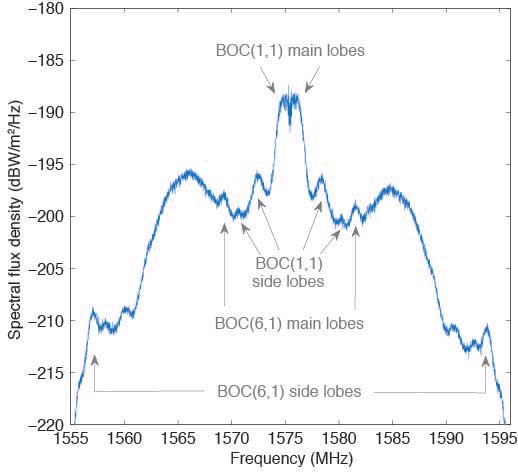
Observations. The German Aerospace Center (DLR) operates a 30-meter dish antenna at its ground station in Weilheim, near Munich, Germany. FIGURE 3 shows the L1 spectrum of SVN74 measured on January 15, 2019. One can clearly see the L1C BOC(1,1) main lobes at 1574 and 1576 MHz as well as the BOC(6,1) main lobes at 1569 and 1581 MHz. Selected side lobes are also indicated.
Figure 3. SVN74 L1 spectral flux density measured with the Weilheim 30-meter antenna on January 15, 2019, at 08:04 UTC. Selected features of the L1C signal are indicated by arrows. (Image: Authors)
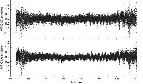
Initially, none of the International GNSS Service network receivers could track the L1C live signal of SVN74, but dedicated firmware versions supporting L1C tracking were soon made available by selected manufacturers. FIGURE 4 shows the multipath linear combination for the L1 C/A-code and the L1C signal tracked with a Javad TRE-G3TH receiver. Reduced measurement noise (multipath plus receiver measurement noise) of the L1C signal can be seen over all elevation angles ranging from about 3 to 83 degrees. (Tracking of the pass began at 4.3 degrees and ended at 3.0 degrees.)
Figure 4, Multipath linear combination (L1 pseudorange and L1 and L2 carrier phase) of the SVN74 L1 C/A-code (top) and L1C signal (bottom) from 1-Hz data of February 3, 2019, tracked with a Javad TRE-G3TH receiver at the Geodetic Observatory Wettzell. (Image: Authors)
The overall root-mean-square noise of the SVN74 pass shown in Figure 4 is 32 centimeters for the L1 C/A-code signal and 24 centimeters for L1C, that is, a reduction of 25 percent for L1C. Compared to the BPSK modulation of the legacy C/A-code signal, the increased steepness of the TMBOC correlation function offers lower measurement noise for the L1C tracking. In addition, the sensitivity to multipath is reduced.
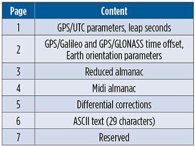
CNAV-2. Together with L1C, the second version of the civil navigation message, namely CNAV-2, is being transmitted. CNAV-2 is composed of three subframes: subframe 1 contains information about the current epoch. Subframe 2 comprises clock and ephemeris data including inter-signal corrections (ISCs). ISCs provide clock corrections for single-frequency users and dual-frequency users utilizing signals other than L1 P(Y) and L2 P(Y). Whereas the essential broadcast ephemeris data in subframe 2 repeat continuously over the validity period of typically two hours, subframe 3 contains pages with alternating content as listed in TABLE 1 (page 41).
Table 1 Currently defined pages of the CNAV-2 subframe 3.
Despite a different message layout, most CNAV-2 parameters and their values match those transmitted in the CNAV message of the L2C and L5 signals. Additional parameters comprise the ISCs for the L1C signal. Compared to the LNAV legacy navigation message, CNAV and CNAV-2 utilize an extended set of ephemeris parameters that allow for a smoother orbit representation compared to LNAV. Multi-GNSS applications benefit from the GPS/GNSS time offset (GGTO) parameters included in page 2. In the same page, Earth orientation parameters are provided that are relevant for users of an inertial frame, such as for spaceborne navigation. The CNAV-2 repeat cycle of 18 seconds allows for a faster access to broadcast ephemerides included in subframe 2 compared to LNAV. Compared to CNAV, CNAV-2 furthermore provides a more sophisticated error detection and correction scheme.
As of the beginning of February 2019, only pages 1, 2 and 4 of CNAV-2 subframe 3 are being used. Within a cycle of 144 seconds, page 1, page 2 and six sets of page 4 midi almanac data (each for one individual satellite) are transmitted. The full almanac for 32 satellites is thus transferred in an average of about 13 minutes. The content in these subframes corresponds to that in L2 and L5 CNAV messages. Updates of CNAV-2 are performed in two-hour intervals starting at 01:30. This is the same update scheme as for CNAV but different from LNAV where the two-hour intervals start at 00:00.
Note that some time will pass before enough GPS III satellites are transmitting so that users can fully enjoy the benefits of the new L1C signal.
MANUFACTURERS
Spectral measurements at the Weilheim 30-meter antenna were made with a Rohde & Schwarz FSQ26 vector signal analyzer. Receiver measurements have been collected with a JAVAD GNSS TRE-G3TH receiver running an L1C-capable firmware version.
PETER STEIGENBERGER and OLIVER MONTENBRUCK are scientists at the German Space Operations Center of the German Aerospace Center (DLR). STEFFEN THOELERT is an electrical engineer at DLR’s Institute of Communications and Navigation. RICHARD B. LANGLEY is a professor at the University of New Brunswick and editor of the Innovation column for GPS World magazine.
Raytheon Company’s GPS OCX program is ready for the U.S. Air Force’s launch of the first modernized GPS satellite later this year.
Raytheon’s GPS Next-Generation Operational Control System, known as GPS OCX, is in its final software development phase. This phase focuses on increasing automation and building controls for both L1C, a civilian GPS signal aimed at increasing international access, and M-code, a military GPS signal with better anti-jam capability.
Once complete, the team will begin integration and testing to keep the program on track for full system delivery in June 2021.
The GPS Operational Control System’s launch and checkout system will control launch and early orbit operations and the on-orbit checkout of all GPS III satellites. (Image: Raytheon)
“Our team has two primary goals this year,” said Dave Wajsgras, president of Raytheon intelligence, information and services. “We will support the U.S. Air Force’s GPS III launch this fall and complete the software build for the full operational system by year’s end.”
GPS OCX is the enhanced ground control segment of a U.S. Air Force-led effort to modernize America’s GPS system. The program is implementing 100 percent of DODI 8500.2 “Defense in Depth” information assurance standards without waivers, giving it the highest level of cybersecurity protections of any DoD space system, Raytheon said.
For protection against future cyber threats, the system’s open architecture allows it to integrate new capabilities and signals as they become available.
Because GPS OCX can manage nearly twice the satellites of the current system, it will increase signal strength in hard-to-reach areas like dense cities and mountainous terrain.
Also, advanced automation will free crews to focus on mission-critical tasks such as updating satellite positions more often.
Two British technologists backed by the U.K. Ministry of Defense have filed patents on the future interoperable GPS and Galileo signal designs that severely disrupt modernization plans for both systems and suddenly, unexpectedly place receiver manufacturers in a highly uncertain and unfavorable situation. Some of the patents have been granted in the U.K. and in Europe, and applications are pending in U.S. patent court, with a ruling expected at any time.
Companies in the United States and outside the country are being approached and asked to pay royalties, on the basis of the patent filings, for use of the European E1 Open Service signal and the modernized GPS L1C signal. Should such initiatives prevail, costs would presumably be passed along to end users of GPS and Galileo — the same taxpayers who have already paid once for the systems.
The purveyor of the royalty solicitations is Jim Ashe, vice president for sales and intellectual property at Ploughshare Innovations Ltd., Hampshire, UK. The patents, if successfully used to collect fees from satellite manufacturers or receiver manufacturers, would have a chilling effect on the use of the new interoperable signals that all parties have labored so hard, for so long, to design. They could quite possibly lead to a return to a BOC(1,1) structure for these signals, losing the benefits of MBOC.
“There’s quite an argument going on,” said one person familiar with the controversy. “Some of the methods of arguing have not been too kind.”
The Background. A great deal of work was accomplished cooperatively between the United States and the European Union (EU) to develop the landmark 2004 signal agreement that emerged from the Galileo Signal Task Force, formalizing cooperation on satellite navigation between the United States and more than two dozen European countries, including the U.K. Part of that agreement concerned a common signal structure (spectrum) for the civilian signals for both the E1 Open Service (OS) signal — the Galileo equivalent of GPS L1 — and the new U.S. GPS L1C signal to be implemented on the GPS III satellites, coming as early as 2015.
The EU said during that process, in effect, “Even though we have agreed on this, Europe wants to be able to optimize the E1 OS signal beyond the agreement on that civilian signal being a binary offset carrier BOC(1,1) signal.” Both international entities had agreed that would be the waveform or the spectrum of the new signal.
The Europeans began to evaluate methods of optimizing their signal. They had some designs called composite binary coded symbols (CBCS), a mechanism of putting a higher frequency componenent into the signal structure, and also a version called CBCS*, meaning that they found there was a bias generated by that extra signal, and so they had to invert every other one of its repetitions.
The signal structure that they were playing with was centered on a plus and a minus 5-MHz component. (Actually five times 1.023, because of the inherent clock of GPS, you can think of it as 1.023 MHz. Everyone in doing compatible or interoperable signals agreed upon that; when reference is made to 5 or 10 MHz, or an even 5 or an even 10, it means that number multiplied by 1.023).
The Europeans were were putting an additional BOC signal on top of the BOC 1,1, and it would have plus or minus 5 MHz as the centers of those two BOC peaks, and then some kind of waveform to modulate that.
The United States pushed back against that to some degree, and proposed adoption of the so-called MBOC waveform, in which case the U.S. signal was equally optimized with a concept called time-multiplexed BOC (TMBOC). The Europeans used the CBOC approach. So, very different ways of doing this. In the European way, they transmitted a continuous but very low-power BOC(6,1) term. The U.S approach transmits four BOC(6,1) chips out of every 33 chips of code (see “Future Wave” sidebar).
A chip in this case means a part of the spreading code, so each signal has its spreading codes, just like the C/A code is a spreading code, meaning a pseudorandom code modulating the carrier. L1C and E1 OS have a pseudorandom spreading code.
The U.S. approach does not put BOC(6,1) components onto the data; that’s what is commonly called MBOC. The U.S. approach is TMBOC, on the pilot carrier only, not on the data component. The European system is like two separate signals, the BOC(1,1) signal having both pilot and data, and a BOC(6,1) signal having both pilot and data. They’ve put the (6,1) into both data and pilot components.
Cue the Antagonists. Part of the task force from Europe and the United States considering the future signals’ make-up were Tony Pratt and John Owen, who works for the U.K. Ministry of Defense and whose office sponsored Pratt’s work. The two participated heavily in all these signal discussions. They stated in early meetings they planned to file patents in some areas.
“Frankly,” states one source, “people should have paid more attention when they said that, and asked ‘What do you mean, and how’s it going to work, etcetera?’ And secondly, there probably should have been a written agreement between parties that nobody will take advantage or patent any of these ideas that we are developing.”
Pratt and Owen filed a number of patents domestically, in the U.K., and and in the European Union, in 2003 and in 2006, and in other places around the world, such as Japan, Canada, and in the United States as well. Some of the U.K. and European patents have been granted. The first of some of those U.S. patents may be issued in the near future.
The original patent filings were later amended to include new claims. The new claims were much more specifically oriented toward TMBOC and CBOC, whereas the original claims were more generally oriented toward modulated methods. The claims have been modified over the years; this is fairly standard patent practice.
As a result, the original 2003 patent doesn’t necessarily read on a particular signal, but its early filing date has precedence. The claims have been updated and modified, and if the patent office issues those, as a true patent, then the new claims apply. Plenty of big patent battles have been fought over just such issues.
Once the patent is issued, a satellite or receiver manufacturer must assume that it is valid, and has only two responses to make, other than acquiescing to royalty claims. The manufacturer can either say, if building a product, “No, my product does not infringe, and I will prove that it doesn’t.’” The other choice for manufacturers is to go back into the patent office and sue the patent filer (and grantee) in the patent courts and prove that the patent was invalid in the first place that the patentee should not have been granted it.
The United States and others were taken off-guard when the U.K. company Ploughshare, which is owned and controlled by a part of the British MoD called Defense Science and Technology Laboratory (DSTL), started making claims on manufacturers. The DSTL is similar to the U.S. Defense Advance Research Products Agency (DARPA), which is credited with inventing the Internet. If taxpayer money goes into something new and interesting, it is considered in some circles legitimate to file patents on those and attempt to recover taxpayer money through royalties on that taxpayer investment. That concept is not being challenged. Questions as to whether the patents are legitimate are very much in discussion.
Ploughshare has contacted companies, saying, “If you use these signals coming from either the European satellites or the U.S. satellites, we will go after companies using these signals.” There are different patents issued, one by the European Patent Office, applying to most of the EU countries, that applies directly to the TMBOC signal, the E1 OS signal, and possibly also to Europe’s E5 signal, which is E5a and E5b; and there is also a patent for GPS III, the L1C signal.
“If you take the patent that hits TMBOC, and you take the broadest possible interpretation of that patent against receiver companies, it says: if you bring into your antenna and process that signal, whether you use all parts of it or not, for instance if you use the BOC(1,1) and not the BOC(6,1) part — then you infringe the patent. Others argue that if you don’t use both components, you don’t infringe.
“But the claim is written broadly enough that it would apply to any receiver receiving and processing the signal. Nobody says what processing means. The patent says if you receive and process the TMBOC signal, as defined in the prior claim, you infringe the patent.
“There is confusion as to whether that will apply or not apply — some people expect that it doesn’t and some people think that it might. That’s up in the air.”
George Is Getting Upset. Various factions in the United States are upset by and trying to figure out what to do about the impasse. From a government point of view, there are three paths that the U.S. government can follow:
Put pressure on the U.K. diplomatically. That would be up to the State Department to put pressure on the EU or the U.K. in particular. The EU and the continental Europeans are equally furious at the British for doing this, as far as parties in the U.S. understand. This can’t be stated as a fact but is widely understood and thought to be the case. The diplomatic approach has its limits, obviously.
Go into Europe and fight the patents in European patent court and try to prove them invalid, to invalidate the patents. Companies could do the same thing, go into various courts, whether they be U.S. or European or Japanese, and say: “Our receivers don’t infringe,” and then have to prove that to the court; or say “The whole patent should not have been allowed, and I’ll fight the legitimacy of the patent.”
Some believe — and there is controversy and anger on this point — that, just as Galileo’s IOV satellites have the capability to transmit without the BOC(6,1) component, the United States should be able to do that with the GPS III satellites as well. Because if the signal is not there, and if the receivers are therefore not designed to process the signals that are not there, then the patent no longer has any relevance.
“If we are to turn off the BOC(6,1) term for a period of time until the legal or diplomatic or other approaches worked, then we would be able to turn the BOC(6,10) term back on again, and return to the original agreed MBOC and TMBOC signals. That requires some coordination between the United States and Europe, and it requires some work to make that possible in the GPS III satellites, putting a switch in the GPS III satellites to permit the operators to turn that (6,1)BOC on and off. This is being hotly debated.”
Some parties object, stating that L1C is too important a signal to mess with, and this proposal runs the risk of slowing down the program, and/or making it more expensive. They believe strongly that the off/on switch is not the best or most far-sighted option: why should the United States be forced to change its signal design due to an illegitimate patent, and in the end wind up with a less capable system?
It is not publicly known whether the Air Force is or is not looking into that option.
During the week of June 25 there was Working Group-A meeting in Washington D.C. followed by a plenary meeting between the EU and United States. The patent controversy was presumably discussed in some fashion, but whether formally addressed or lurking in the background is unknown at this time.
“There is some naivete around this,” said the magazine’s soure. “It’s a serious threat. People think maybe they’ll only go after the high-end receivers, and maybe the royalties won’t be so bad. Ploughshare is trying to lull people into a false sense of security. The impact of this will be great unless it is defeated.”
“The L1C waveform originally was to have been a pure BOC(1,1) (a 1.023 MHz square wave modulated by a 1.023 MHz spreading code). Negotiations between the U.S. and the European Union (EU) at that time resulted in an agreement that both GPS and Galileo would use a baseline BOC(1,1) signal. However, the EU reserved the right to further optimize their signal within certain bounds. Some of the optimization proposals were known as CBCS and CBCS*. However, in further EU/US discussions it was decided that L1C and the Galileo E1 open service signal should have identically the same spectrum. This was a significant challenge because of different baseline signal structures and existing designs.
“The breakthrough came when [U.S. representative] John Betz proposed what is called MBOC. The MBOC waveform has 10/11th of its power in BOC(1,1) and 1/11th in BOC(6,1). However, L1C and E1 OS achieve this result in very different ways. The Galileo technique is called CBOC. The GPS technique is called TMBOC. Whereas Galileo has a 50/50 power split between pilot and data and includes the BOC(6,1) component in each, GPS includes the BOC(6,1) waveform only in the pilot component by modulating four of every 33 spreading code chips with a 6 MHz square wave and 31 chips with a 1 MHz square wave. With 75 percent of the power in the pilot, the result is 3/4 x 4/33 or 1/11, as required. It is likely the BOC(6,1) signal component will be ignored by consumer-grade GNSS receivers where a narrow RF bandwidth is preferred. Fortunately that is a loss of only 12 percent (0.56 dB) of the L1C pilot power. However, for commercial and professional grade receivers, the extra waveform transitions (wider Gabor bandwidth) can be used to improve code tracking signal-to-noise ratio, and with certain advanced techniques it should be possible to improve multipath mitigation. This final point depends on careful control or calibration of the transmitted code timing and symmetry.”
By Thomas A. Stansell, Kenneth W. Hudnut, and Richard G. Keegan
The new GPS L1C signal will be broadcast by the Block III satellites, with first launches as early as 2014. L1C innovations significantly enhance PNT performance as well as interoperability with other GNSS signals. The authors describe the benefits of its new features and how best to make use of each one.
A highly evolved racehorse of a signal with outstanding technical performance, L1C was designed to significantly improve autonomous navigation, and to be interoperable with L1 signals from other GNSS providers. Its structure evolved from the earliest GPS signals: it shares with the C/A signal the L1 center frequency of 1575.42 MHz, coherence between the carrier frequency, the code clock rates, and the data rate, and the provision of a navigation data message.
L1C inherited significant improvements from subsequent developments, specifically WAAS, L5, and L2C. WAAS was the first GPS-related signal to use forward error correction (FEC) for its data. L5 was the first open signal design to use longer spreading codes (10,230 chips), to have separate data and data-less (pilot carrier) signal components, to employ an improved navigation message structure (CNAV), and to employ overlay codes to achieve a longer equivalent code length, improve correlation performance, and eliminate the need for bit synchronization. The L2C signal adopted most of these improvements but, instead of an overlay, substituted a much longer pilot carrier spreading code, not only to optimize correlation performance but also to decrease the number of time ambiguities after tracking the spreading codes.
The L1C signal design is amazing, not only because of its highly evolved and outstanding technical performance but also because a committee designed this racehorse of a signal rather than it becoming a camel. Table 1 lists key members of the L1C technical committee in alphabetical order. The list has two groups, technical contributors and government chairpersons. When each new signal aspect is introduced, the key contributor or contributors from this list will be identified.
Table 1. Key L1C contributors.
L1C is intended to be interoperable with L1 signals from other GNSS providers. To identify its signal type, we note that Galileo officials have identified three types of services, “open”, “commercial”, and “publicly regulated”. An open service is freely available to all users. A commercial service is limited to users who pay a fee to access the signal, which otherwise is denied by encryption. A publicly regulated service (PRS) also is encrypted but intended only for public safety applications. GPS is adopting the open service definition but will continue to distinguish encrypted signals as “military” because there are no encrypted commercial GPS services. L1C will be a new GPS open service signal, joining L1 C/A, L2C, and L5.
Although the term “civil signal” often is used, there can be confusion about its meaning. Within the U.S. government it is common to use the word “civil” to mean civil government agencies, e.g., the Department of Transportation (DOT). However, it’s clear the GPS C/A, L2C, L5, and L1C signals are “open” and intended for use by anyone. Therefore, we will use the term “civilian” or “open” in order not to imply that any of these signals is restricted in its use.
L1C Signal Development
The L1C signal structure has evolved from the earliest GPS signals first launched in 1978. It shares with the C/A signal the L1 center frequency of 1575.42 MHz, coherence between the carrier frequency, the code clock rates, and the data rate, and the provision of a navigation data message. Significant improvements have been inherited from subsequent developments, specifically WAAS, L5, and L2C. For GPS or GPS-related signals, WAAS was the first to use forward error correction (FEC) for its data. L5 was the first open signal design to use longer spreading codes (10,230 chips), to have separate data and data-less (pilot carrier) signal components, to employ an improved navigation message structure (CNAV), and to employ overlay codes to achieve a longer equivalent code length, improve correlation performance, and eliminate the need for bit synchronization. The L2C signal adopted most of these improvements but, instead of an overlay, substituted a much longer pilot carrier spreading code, not only to optimize correlation performance but also to decrease the number of time ambiguities after tracking the spreading codes, i.e., extend the duration of GPS time ambiguity from 1 ms after tracking the C/A code and 20 ms after tracking the L5Q code to 1.5 sec for L2C.
Before giving details of the L1C signal in which we identify the primary contributor(s) for each innovation, it’s appropriate to recognize the special contributions of two members of the L1C technical team.
The first is Dr. Charles R. (Charlie) Cahn. Cahn has been a major contributor to GPS since before GPS was conceived. In particular, he was a key contributor to the Air Force 621B program which anticipated GPS. (He, Dr. James J. (Jim) Spilker, Dr. Robert Gold, and Mr. Burt Glazer deserve most of the credit for developing the original GPS C/A and P code signal structures, other than the NAV message.) Cahn discussed the merits of having a separate data-less or pilot channel in a 621B report [1], with Stansell he again recommended this for GPS in a 1975 Spartan Study Report, and finally the idea was adopted by the RTCA for L5 in accordance with recommendations from Cahn, Stansell, and Keegan. Also, Cahn was the first to recommend an overlay code on the L5 data signal to eliminate the need for the always problematic bit synchronization process. In a step toward L1C, Cahn was a primary contributor to the L2C design. In particular, he designed the code generators, including the 1.5 sec pilot code, and the chip by chip multiplexing technique which permitted two signal components in one bi-phase signal. In addition to consulting for The Aerospace Corporation and several commercial GPS companies, Cahn recently invented a more effective method to combine multiple signals on one carrier, called Phase-Optimized Constant-Envelope Transmission (POCET) modulation [2]. It is expected to be used on later versions of GPS III satellites to improve transmitter efficiency.
The second special recognition is for Dr. John Betz. Betz has played a very significant role for more than a decade in helping define the military M-code, in working with international partners to define and negotiate compatibility and interoperability signal parameters, in helping negotiate a significant part of the 2004 EU/US agreement, and in evaluating and supporting a wide variety of GPS programs and initiatives. Betz was a vital contributor to the overall L1C design through interaction with other team members, development of ways to compare alternatives, suggesting use of new signal processing concepts, and bringing experts from MITRE who performed significant analyses and developed key signal components.
Table 2 lists, in order of the authors’ judgment of value to user communities, the most important new characteristics of the L1C signal. The list also shows the primary contributor(s) for each characteristic.
Table 2. L1C Innovations in order of judged value.
Improvements made to the previously modernized civilian GPS signals, L5 and L2C, were a starting point for the L1C design. These included: having a pilot carrier; longer spreading codes (10,230 chips minimum); overlay or long pilot codes to eliminate the need for bit synchronization, to improve correlation properties, and to decrease the number of time ambiguities aft
er locking to the spreading codes; use of FEC to improve data demodulation performance and provide bit synchronization; and the flexible and higher precision CNAV message. The following paragraphs describe the additional improvements incorporated in L1C.
A key issue was whether additional signals could be added to the L1 carrier without negatively impacting legacy signals. Several combining methods were considered, and it was determined that, with the right combining technique, L1C could be added without detriment. Use of POCET, subsequently invented by Cahn, will further enhance this capability.
An “industry standard” rate ½ constraint length 7 convolutional coding method had been adopted for forward error correction (FEC) on WAAS, L2C, and L5 signals. However, the team agreed it was appropriate to consider other possibilities. Betz arranged for Ma to address the team on at least two occasions, providing a good tutorial on other advanced FEC methods which would allow message demodulation at even lower signal-to-noise ratios.
While the FEC options were being considered, another breakthrough occurred. Since at least 1999 Stansell had encouraged development of a way to take better advantage of GPS message redundancy. Rising to this challenge, Kovach proposed a modification of the CNAV message structure that he and Art Dorsey (Lockheed-Martin) had developed for L5 and L2C. The modified message, called CNAV-2, is equally flexible, equally precise, but more efficient, allows faster time to first fix (TTFF), and permits message demodulation at signals as weak as the carrier can be tracked. This final attribute requires FEC encoding of entire message blocks (sub-frames) rather than having the continuous process used for L2C and L5. As a result, when signal levels are very weak, bit symbols from two or more messages can be combined to improve the energy available per symbol, i.e., the L1C data demodulation threshold can be improved by combining symbols from two or more messages.
As a result of the message format improvements and performance evaluations by Shane, the team settled on the Low Density Parity Check (LDPC) FEC block encoding technique. This technique is as effective as turbo codes but without intellectual property constraints. Software developed by Shane was used by Sklar and Wang to define the specific L1C implementation, with performance simulation help from Kasemsri and Zapanta.
The most important new attribute of L1C resulted from a proposal by Betz to take advantage of the improved FEC and message redundancy attributes of L1C by having two separate data messages. Half the total signal power would be in the pilot carrier and the other half would be split evenly between two messages, one with full precision and the second with less precision but which could be acquired more quickly for faster TTFF. Stansell appreciated the opportunity for less power in the message but recommended that instead of having a second message the saved power should be added to the pilot carrier, for a 75/25 split between pilot and data power. The reasoning was that code and carrier measurements on the pilot are vital to navigation whereas messages are redundant, slowly changing, and are becoming available from other sources, such as the Internet and from cell phone networks. The issue was settled by an international survey of manufacturers, universities, and government organizations. The final L1C signal design, with the 75/25 power split, was selected by these experts from a group of five signal options.
Another L1C message innovation came about through a collaboration between Kovach and Cahn. The idea was to have a separate message sub-frame with very powerful encoding to identify GPS time of week to within a two hour interval. The sub-frame is called Time of Interval (TOI), and Cahn recommended a 52 symbol (26 bit) BCH code to provide the 9 bits of TOI information. Although orbit parameters may be available from a number of sources, precise and unambiguous time is vital for navigation, and TOI serves this and other purposes. With this level of encoding, TOI can be obtained from just one message at very low signal levels. Furthermore, the identical TOI is broadcast from every GPS satellite at the beginning of every 18 second L1C message. Therefore, it is possible to combine symbols from two or more GPS signals to demodulate TOI even under very adverse signal conditions. After locking to the pilot code and its overlay, one TOI establishes time of week within ±1 hour for all GPS signals.
TOI is particularly effective because of a recommendation by Cahn to overlay the pilot spreading code with another code which frames the entire data message. The L1C overlay code is 18 seconds long (the message length) and is unique to each GPS satellite. Because of this, the TOI defines which of the 400 possible 18 second intervals within a 2 hour time span begins at the next message frame, which also is the beginning of the next overlay code. If receiver time is known or can be determined to within an hour, TOI and the GPS spreading codes establish time for all GPS satellites.
Although it would have been adequate to adopt spreading codes from the L5 signal design, Betz introduced Rushanan to the L1C technical team and recommended that he study alternate code structures with improved characteristics. After an extensive study, Rushanan recommended a set of length-10223 Weil-codes extended with a fixed 7-bit pad to provide the primary L1C spreading codes. These codes have improved performance characteristics, as detailed in [3], [4], and [5]. In addition, the team asked Rushanan to define the 1800 chip pilot overlay codes, also described in [3], [4], and [5]. Stansell specifically requested that Rushanan optimize the ability to synchronize to the overlay code with as little observation time as possible. As a result, within one or two seconds after a signal is acquired, its 18-second time frame is established. After the first satellite is acquired, the maximum time difference for signals from other satellites is less than ±10 ms for receivers near the earth, so only two possible states of the overlay code must be examined to resolve the 18 second message phase for any other satellite. If the GPS almanac, an estimated position, and even a rough time estimate are available, as usually is the case, message time phase can be resolved even faster for subsequent signal acquisitions.
The L1C waveform originally was to have been a pure BOC(1,1) (a 1.023 MHz square wave modulated by a 1.023 MHz spreading code). Negotiations between the U.S. and the European Union (EU) at that time resulted in an agreement [6] that both GPS and Galileo would use a baseline BOC(1,1) signal. However, the EU reserved the right to further optimize their signal within certain bounds. Some of the optimization proposals were known as CBCS and CBCS. However, in further EU/US discussions it was decided that L1C and the Galileo E1 open service signal should have identically the same spectrum. This was a significant challenge because of different baseline signal structures and existing designs. The breakthrough came when Betz proposed what is called MBOC. The MBOC waveform has 10/11th of its power in BOC(1,1) and 1/11th in BOC(6,1). However, L1C and E1 OS achieve this result in very different ways. The Galileo technique is called CBOC, as described in a number of papers. [8], [9], and [10]. The GPS technique is called TMBOC and is defined by IS-GPS-800A [11] as well as by [3], [4], [5], and [8]. Whereas Galileo has a 50/50 power split between pilot and data and includes the BOC(6,1) component in each, GPS includes the BOC(6,1) waveform only in the pilot component by modulating four of every 33 spreading code chips with a 6 MHz square wave and 31 chips with a 1 MHz square wave. With 75% of the power in the pilot, the result is 3/4 x 4/33 or 1/11, as required. It is likely the BOC(6,1) signal component will be ignored by consumer grade GNSS receivers where a narrow RF bandwidth is preferred. Fortunately that is a loss of only 12% (0.56 dB) of the L1C pilot power. However, for commercial and professional grade receivers, the extra waveform transitions (wider Gabor bandwidth) can be used to improve code tracking signal-to-noise ratio, and with certain advanced techniques it should be possible to improve multipath mitigation. This final point depends on careful control or calibration of the transmitted code timing and symmetry.
Finally, Dafesh recommended that the team consider data symbol interleaving. The team accepted this suggestion, and Sklar and Wang designed the interleaver. Because of the powerful FEC, by scattering data symbols throughout sub-frames 2 and 3, it is possible to recover an entire message even if portions are blocked by, for example, walking or driving past trees or other obstructions.
All team members deserve credit for sharing, challenging, and improving concepts. Particular examples are the strong aviation navigation background provided by Hegarty and the in depth design experience for a wide range of receiver types and civilian applications provided by Keegan. In addition, Yi had the primary responsibility for documenting L1C in IS-GPS-800.
It also is important to recognize the contributions of the many professionals who responded to the worldwide survey of manufacturers, universities, and government experts. Stansell conducted each of the survey presentations, some in person and others over the Internet. One or more of the Government Chairpersons also participated, usually Hudnut or Lenahan. There were responses from organizations in 10 countries: Japan (34), the USA (26), Russia (7), the United Kingdom (5), Canada (4), Australia (1), Finland (1), Germany (1), Switzerland (1), and Taiwan (1). This is not a complete picture because a number of the responses were from individual experts while others were a consensus response from a larger group. Five signal design options were presented, and the preferred design received 62 percent of the 81 responses. As a result, the L1C signal has a 75/25 split between pilot and data power and the data rate is 50 bits per second.
L1C Signal Description
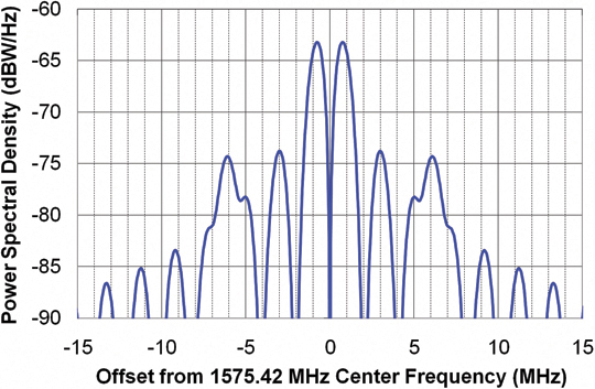
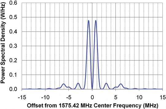
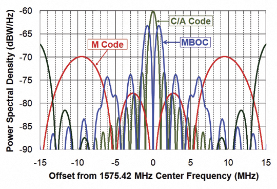
The official L1C signal description is given by IS-GPS-800; the most recent version A was released on June 8, 2010. Figures 1 and 2 show the L1C power spectral density with, respectively, a logarithmic (dBW/Hz) scale and a linear (Watts per Hz) scale. Figure 3 is the same as Figure 1 but also includes the C/A and M Code signals; it assumes both signals are transmitted with the same total power.
Figure 1.Figure 2.Figure 3.
These plots illustrate three important aspects of the L1C spectrum. First, L1C is designed to have only a small impact on reception of the legacy C/A signal. This is important for the compatibility of signals with respect to each other. A good way to evaluate the impact of one signal on another is called the Spectral Separation Coefficient (SSC), which quantifies the amount of interfering power from one signal to another, under the assumption that each signal is transmitted with the same power but with different spreading codes.
The SSC between a C/A signal and the L1C signal is –68.3 dB/Hz. The spectral separation illustrated in Figures 1, 2, and 3 assures that L1C signals will have very little impact on acquiring and tracking the legacy C/A signals. Therefore, L1C is judged to be compatible with the C/A signal.
Figure 3 also illustrates that L1C and the M Code signals have very little impact on each other. The SSC between L1C and M Code is –82.8 dB/Hz. This is important because M-Code power may be substantially higher than the civilian signals, so a larger negative SSC is important to maintaining compatibility.
The third aspect of the L1C spectrum is the additional signal power at ±6.138 MHz. This component of signal power differentiates a binary offset carrier BOC(1,1) waveform from the L1C multiplexed BOC or MBOC waveform. Exactly 1/11th of the L1C signal power is a BOC(6,1) component, whereas 9/11th of the power is a BOC(1,1) component.
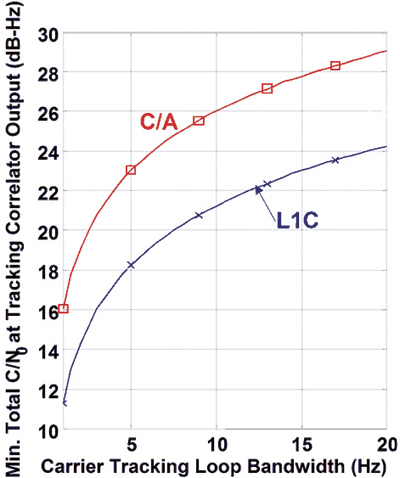
75 Percent in the Pilot Carrier. Figure 4, which shows the required post-correlator C/N0 required to phase track either the L1C or C/A signals as a function of tracking loop bandwidth, illustrates the main advantages of having 75 percent of the L1C signal power in the pilot component. The carrier-tracking threshold for equivalent signal power using a Costas loop is 6 dB worse than tracking with a phase-locked loop (PLL). A Costas loop is needed for the C/A signal because it is modulated by data, whereas a PLL can be used for the dataless L1C pilot signal. This 6 dB advantage more than compensates for having only 75 percent (-1.25 dB) of the L1C power in the pilot. The vertical displacement between the two curves illustrates the 4.75 dB L1C tracking threshold advantage.
Figure 4. Required post Correlator C/N0 versus tracking loop bandwidth.
The horizontal displacement of the curves shows another L1C advantage. For a given C/N0 threshold, the L1C loop bandwidth can be increased by a factor of three. In turn, this allows tracking with G forces 32, or nine times higher. For third-order loops capable of tracking acceleration, this allows tracking with 27 times higher jerk. Such differences are likely to be more important than tracking threshold for high-dynamic applications such as machine control.
Although Figure 4 assumes the L1C and L1 C/A signals have the same total power, the minimum received L1C signal power specified in IS-GPS-800A is –157 dBW, and the equivalent for C/A in IS-GPS-200E is –158.5 dBW. In other words, the intent is for L1C to be transmitted with 1.5 dB more power than C/A. Therefore, the figure is conservative by 1.5 dB in evaluating the L1C advantages over C/A. Thus, the actual threshold advantage is 4.75 + 1.5 = 6.25 dB.
For narrowband or other receivers not punctual correlating the BOC(6,1) signal component, the pilot carrier is 29/33 or 0.56 dB weaker, so the net advantage is 4.75 – 0.56 + 1.5 = 5.69 dB.
LDPC Block Encoding
Low-density parity check (LDPC) encoding provides three key advantages. First, to demodulate the critical part of the L1C message with a bit error rate (BER) of 10-5 requires an Eb/N0 (ratio of energy per bit to the noise power in a 1-Hz bandwidth) of 2.2 dB versus 96 dB for the C/A signal. When taking into account that only 25 percent of L1C signal power is in the data component, the required total power of the L1C signal can be 1.4 dB less than the C/A signal for an equivalent BER. As a result, this performance allows the pilot component of L1C to have 75 percent of the total L1C power.
Second, LDPC gives near-optimum performance with no intellectual property constraints. Third is the ability to block-encode Subframes 2 and 3 of the L1C message, described next.
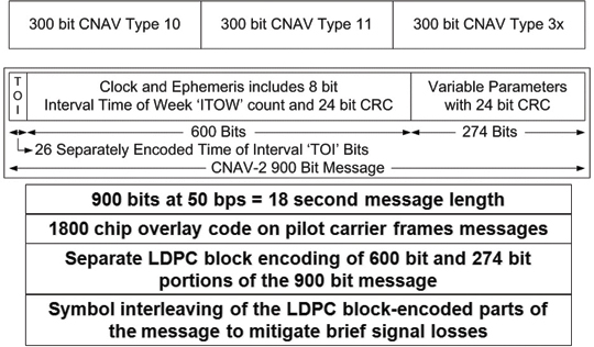
CNAV-2 Message. Figure 5 compares the L5 and L2C CNAV message structure to the L1C CNAV-2 structure. CNAV was a major step forward compared to the original NAV message in terms of flexibility, precision, time to first fix (TTFF), and integrity. Instead of the fixed 30-second structure of the NAV message, CNAV consists of multiple six-second messages that are differentiated by a message-type number. The sequence of broadcast message types is defined by the GPS control segment, which greatly improves flexibility. The round-off error in the NAV message can affect pseudorange calculations
by up to 40 centimeters, whereas the equivalent CNAV error contributes about 3 centimeters. Orbit and clock precision is substantially improved. Because a minimum of three message types are needed for the necessary orbit and clock parameters, as little as 18 seconds is needed to gather the necessary information after locking to a signal. On the other hand, if four message types are being sent sequentially, and the receiver locks just after the beginning of a message, it can take 30 seconds to gather the necessary data. TTFF typically is improved. Importantly, each CNAV message includes a 24-bit cyclic redundancy check (CRC) word that makes it practically impossible to have bit errors in a message that passes the CRC check.
Figure 5. CNAV and CNAV-2 message structures.
CNAV-2 improvements to the CNAV structure all but guarantee an 18-second TTFF after signal acquisition. Message efficiency is improved by eliminating the need to identify each six-second message, to have complete time-of-week (TOW) information in each six-second message, and to have three rather than two 24-bit CRC words every 18 seconds. Even more important, GPS time is defined modulo 18 seconds upon acquisition of only one signal, and it is defined modulo two hours by decoding only one 26-bit, 0.52-second time-of-interval (TOI) word at the beginning of each message. In addition, TOI is so well encoded (52 symbols for nine data bits) that it can be demodulated in very weak signal conditions, which can be further enhanced by combining the identical TOI symbols transmitted by every satellite at the beginning of every 18-second message.
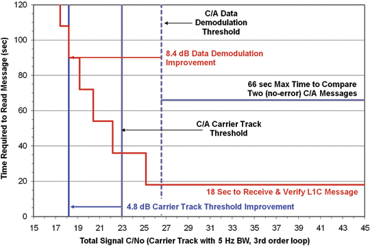
Figure 6 illustrates the ability to combine message symbols from several sequential Subframe 2 data blocks so vital clock and ephemeris data can be demodulated at the weakest signal level the receiver can track. This feature is made possible because the symbols in subframe 2 will not change for at least 15 minutes (50 repeats) and typically no more often than one to two hours (200 to 400 repeats). This provides up to 8.4 dB of message demodulation improvement. The figure also shows other L1C improvements: 4.8 dB of carrier track threshold extension, and a TTFF of 18 seconds after successfully demodulating subframe 2 from the minimum number satellites for a position fix.
Subframe 3 of the L1C message contains less time-critical information such as almanac, ionospheric correction terms, and so on. This subframe also is LDPC block-encoded so it is quite robust, although it does not offer the ability to combine symbols from sequential messages.
Figure 6. L1C and C/A performance comparison.
Pilot Overlay Code
Figure 5 shows that the pilot overlay code consists of 1,800 chips that frame the 18-second message. In comparison with the L5 20-millisecond (ms) pilot overlay code, it not only is 900 times longer but also is unique to each satellite. This improves cross-correlation performance in general and particularly when two satellites have the same pseudorange.
The long L1C overlay code can be acquired reliably after only one or two seconds of signal lock. Its length does not cause a relevant delay in TTFF, but it provides many advantages. First, synchronizing to the overlay code on one satellite defines GPS time for all satellites modulo 18 seconds (in comparison to 1 ms with the C/A code). Even with infrequent use, the receiver’s RTC, which typically is better than 5 parts per million (ppm), should have sufficient accuracy — better than ± 9 seconds — to completely resolve GPS time with one signal acquisition. In 24 hours with a clock frequency error of 5 ppm the time drift would be less than ½ second.
Even if the RTC is in error by several times 18 seconds, resolving accurate time can be done quickly by computing position fixes with multiple time hypotheses spaced 18 seconds apart. Pseudorange changes at rates up to ±1,440 kilometers per 18 seconds. Because some satellites are approaching, others are moving away, and all of them are changing range at different speeds (different Doppler frequencies), determining which position fix is correct out of several 18-second GPS time hypotheses will be straightforward since only one will be reasonable. (Care must be taken to avoid any extremely rare instances where two results may seem reasonable.)
The worst clock error with aided GPS (A-GPS) is ±2 seconds, which is adequate to completely resolve GPS time after acquiring only one L1C signal. This capability can aid acquisition of and navigation with other signals, such as C/A or signals from other GNSS providers. The 18-second overlay code will provide benefits as soon as even a few L1C signals are available.
The L1C overlay code, in conjunction with the repeating symbols of message subframe 2, also enables data demodulation to begin at any point within an 18-second message. It is not necessary to wait for the message frame to begin. The receiver can begin collecting data symbols at any time, and 18 seconds later it will have assembled all the subframe 2 clock and ephemeris information and can begin to navigate. An exception occurs when the satellite message is updated, between once every 15 minutes to once every two hours. This capability significantly improves TTFF whenever satellite messages are needed for navigation, for example, when they aren’t still valid from a previous collection or aren’t provided by an A-GPS service.
Spreading and Overlay Code Designs
The L1C MBOC waveform (time-multiplexed BOC, or TMBOC), shown in Figure 7, enabled GPS and Galileo to have open-service L1 signals with an identical spectrum, although implemented quite differently. L1C places all the BOC(6,1) chips in the pilot carrier. This is because the BOC(6,1) component is intended to improve code-tracking performance by increasing code loop signal-to-noise ratio (SNR) and by allowing advanced multipath-mitigation techniques to have the advantage of more code transitions. Because these measurements are made almost exclusively on the three times (4.8 dB) more powerful pilot signal, there is no reason to lose the code tracking benefit by having BOC(6,1) chips in the data signal component. In addition, narrowband receivers such as those predominantly used for consumer applications cannot process BOC(6,1) chips, so it would be undesirable to deny full message signal power to such receivers.
Figure 7. The GPS MBOC (TMBOC) modulation.
For receivers tracking only the BOC(1,1) component of L1C MBOC, there are on average 43.5 code transitions per 33 chips. For those tracking both components, there are on average 89.5 code transitions per 33 chips. This provides up to 3.1 dB of improvement in code loop SNR for wideband receivers code tracking with both types of chips. (The amount of improvement depends on receiver RF bandwidth.)
Classic multipath-mitigation techniques such as the double-delta don’t work well with the BOC(6,1) waveform, but recent advances promise improvement by using the extra transitions in the MBOC signal. Some developers worry that the full benefit may not be achieved unless code symmetry and time alignment of the two components is better than the signal specification permits. If the satellites cannot provide the needed signal symmetry and alignment, such problems likely can be overcome by ground calibration of these characteristics, either directly by each receiver or indirectly by an observing network.
Symbol Interleaving. Symbol interleaving means that before a message is transmitted, the satellite scatters the 10-ms message data symbols from subframes 2 and 3 throughout these subframes in
a fixed and known pattern. After a receiver has demodulated (or otherwise measured) the symbols belonging in a subframe, they are reassembled into the proper order before the LDPC block decoding is performed. In other words, the scattering done in the satellite is undone by the receiver. The objective is to provide a measure of protection against certain types of signal fading. For example, if a sequence of symbols from the satellite is lost because the receiver passes behind an object such as a tree, only half the symbols in this part of the message would be affected if the adjacent symbols in the original message are received either before or after the signal blockage. Thus, with reasonable signal levels and the benefit of powerful LDPC block encoding, the entire message could be reconstructed.
Performance Metrics and Comparison
A main objective for the L1C signal structure was to significantly improve the autonomous navigation capability for GPS users. Key weaknesses in the current C/A signal include the thresholds for bit synchronization, message synchronization, and data-bit demodulation. To achieve navigation at very low signal levels, users of the L1 C/A signal had to employ external sources for time synchronization, data acquisition, and, to extend the tracking loop threshold, external data-bit aiding to enable phase-locked tracking rather than Costas tracking of the C/A signal. The new signal structure addresses all of these shortcomings and provides a robust autonomous navigation system that requires no external aiding for most commercial applications.
Message Frame Synchronization and Time of Transmission. For autonomous navigation, frame synchronization has two important roles. The first is to set GPS time, modulo frame duration, which is required to establish the unambiguous time of transmission. Frame synchronization, or knowledge of frame start, also enables assembly of the received bits into the appropriate data words. In both L1 C/A and L5, frame synchronization is accomplished by recognizing a synch word within a data subframe, which requires accurate demodulation of data bits. For L1C, frame synchronization is inherent in the signal structure and does not require demodulation of data bits. This is very important for two reasons. The first is to establish GPS time of transmission very quickly, especially when the satellite message is not needed, for example, if it was acquired previously or obtained by other means. The second is when satellite ephemeris data is necessary, but the signals are very weak. The L1C message structure facilitates this capability.
Overlay Code on Pilot Carrier. One frame of data consists of 1,800 symbols modulated onto the data carrier which, at 100 symbols per second, is 18 seconds long. However, synchronized to this 18-second data frame is a pseudorandom code modulated on the dataless pilot carrier. This 100 chips per second overlay code is a linear-shift-register code that is truncated to be 1,800 chips long. The overlay codes were chosen to have very low minor auto-correlation and cross-correlation peaks so a very short segment of the code can be used to establish its underlying code phase.
If a 100-chip segment of the received code is correlated over a replica of the entire code, the proper correlation peak would be easily distinguished, thus establishing the GPS time epoch at the start of the code. Since this code epoch and the start of the data frame are synchronized, the start of the entire data frame is established, modulo 18 seconds. The start of the data frame by definition establishes the GPS time of transmission, also modulo 18 seconds. This is accomplished without decoding a single data bit by using the power advantage of the pilot carrier.
However, using the message to resolve the 18-second time ambiguity often is not needed. For example, the receiver’s real time clock (RTC) is likely to be accurate to within ±9 seconds. Alternately, almost any source of external aiding can provide time to within ±2 seconds. In either case, if the receiver already has a valid satellite ephemeris, navigation can begin after receiving a little over 1 second of the stronger pilot carrier signal. Ephemeris data can be available in a number of ways, including prior reception from the satellite, from a separate communications channel, or from one of several predicted ephemeris sources.
Message Frame – Data Format. A message frame consists of 1,800 symbols that comprise two distinct data types. The first data type, in subframe 1, is the Time of the Frame (TOI or Time of Interval) modulo two hours. The second data type is further separated into two blocks, subframe 2 containing data that is fixed for a period of time and subframe 3 containing data that can change from frame to frame.
Time of Interval Subframe. The TOI is a count of the number of 18-second message intervals in each 2 hour time period. Two hours is the maximum duration of any ephemeris message before being replaced by the satellite. (Fifteen minutes is the minimum.) There are 400 18-second intervals in 2 hours, so it requires 9 bits to represent the 400 intervals. These nine bits are block-encoded into 52 symbols using a BCH(51,8) code, where the 8 data bits are the least significant bits of the TOI. The most significant bit (MSB) of the TOI is then mod-2 added to the BCH codeword and also appended to the resulting codeword as its MSB, resulting in a 52-symbol codeword. This coding provides a BER of 10-5 for an Eb/N0 of –1.9 dB per coded symbol or a C/N0 of +18.2 dB-Hz at the correlator output for the data channel. Since the data channel contains only 25 percent of the total L1C power, the C/N0 of the composite signal would be +24.2 dB Hz. Symbol demodulation is performed using the pilot carrier tracked by a PLL as the phase reference. Since the pilot carrier contains 75 percent of the total power, its C/N0 would be +23 dB-Hz. With a (single-sided) loop-noise bandwidth of 10 Hz, the loop SNR for the carrier channel PLL would be +10 dB.
Note that a 10-5 BER is not required for successful demodulation of TOI. Therefore, weaker signals can be used successfully if the PLL loop bandwidth can be smaller in such weak signal conditions.
The most straightforward method to decode the TOI is brute force maximum likelihood estimation. All possible code words for the 400 possible data words can be pre-computed. Each then can be compared (correlated) with the received code word. The data word that corresponds to the code word with the highest correlation would be the result of the decoding process.
Finally, since all satellites simultaneously transmit the same TOI, the received code word from several satellites can be combined to increase the effective Eb/N0. The target BER of 10-5 thus can be achieved at an even a lower C/N0 than the single satellite value. In this case, the decoding process described above can be performed on a composite code word derived from two or more satellite signals, weighted appropriately for the signal strength from each one.
As an example, consider a receiver with access to an external source of the ephemerides. By combining the TOI code word from five satellites, the average C/N0 required per satellite would only be 17.2 dB-Hz, so time could be established to ±1 hour in slightly over 1 second.
Because of the 18-second overlay code, decoding TOI is not required for receivers with an internal clock good to ±9 seconds or with external time aiding, the worst of which today is within ±2 seconds.
Data Subframes. The remaining data bits are separated into two additional subframes. (TOI is in the first subframe.) The second subframe contains data that does not change for at least 15 minutes, and typically for an hour or two. This subframe provides the satellite ephemeris and the interval time-of-week (ITOW) count, which identifies the start time of the two-hour interval since the beginning of the GPS week, which, in turn, frames the TOI count of 18-second intervals within each two-hour frame. The third subframe contains data that normally changes from frame to frame, such as the satellite constellation almanac.
The block of data containing the satellite ephemeris (subframe-2) consists of 576 clock and ephemeris bits along with a 24-bit CRC, for a total of 600 bits. These are encoded with a rate-½ LDPC Block code into 1,200 symbols. The block of data containing variable data (subframe-3) consists of 250 data bits along with a 24-bit CRC, for a total of 274 bits. These are also encoded with a rate-½ LDPC Block code into 548 symbols. The 1,748 symbols of the two data subframes are combined and interleaved using a simple 38 x 46 row-column block interleaver. These interleaved symbols plus the 53 TOI symbols make up the entire 1,800-symbol (900-bit) message frame.
Since both the LDPC codes and the interleaver operate on independent blocks of data, the resulting symbols for subframe-2 are identical and in the same location in each message frame for between 15 minutes and two hours. Since the data decoding uses the pilot carrier as the phase reference, the subframe-2 symbols can be coherently combined over many 18-second message frames before decoding to improve BER performance.
One reasonable subframe-2 strategy would be to check the CRC after LDPC-decoding the first received message to determine if there are any remaining bit errors. If errors are detected, do the same with the second message. If errors exist in the second message, coherently combine the symbols from the two messages, properly weighted, LDPC-decode the combination, and check the resulting CRC for errors. If necessary, this process can be used on as many messages as needed to obtain a perfect result.
Framing the data messages with the pilot overlay code and the repeating characteristic of subframe 2 permits data collection over any arbitrary 18-second interval. It doesn’t matter where data collection begins. The overlay code tells the receiver which symbol is which, and the repeating subframe-2 message can be compiled from any place in the previous message to the same place in the following message. The powerful CRC assures that a good message is perfect. When the ephemeris is needed from a satellite, rather than from an alternate source, these characteristics allow TTFF to be slightly over 18 seconds, with assurance the information is correct.
Since LDPC FEC has been adopted by the current state-of-the-art wireless standards such as 802.11n and 802.16e, employing it in the latest GPS signal structure should be simple for the receiver designer. In fact, synthesizable cores are available for WiMax LDPC decoders from several sources, and LDPC decoders are as commonplace in wireless signal basebands as Viterbi decoders for the convolutional codes of L2C, L5, and SBAS have become in GPS basebands.
For subframe-2 data, the Eb/N0 required to achieve a BER of 10-5 is approximately 2.2 dB. For subframe-3 data, the Eb/N0 required for this same performance is approximately 2.7dB.
Signal Structure
The L1C signal is a composite of two signals that are phase/frequency coherent with synchronized spreading codes and symbol timing. The pilot signal has 75 percent of the total power, is a carrier-only signal, and is spread by a 10-ms long code plus an 18-second overlay code. The data signal has 25 percent of the total power, is spread by a 10-ms long code, and is data modulated with 10-ms symbols.
Spreading Codes. The spreading code for both L1C signals are 10,230 chip codes with a chip rate of 1.023 MHz, producing a 10-ms long code. This corresponds to one symbol for the data carrier and one chip of the overlay code for the pilot carrier. These codes are not linear shift register sequences like all other codes employed by GPS, but are pseudo-random sequences derived from Weil sequences of length 10223. This sequence is extended by a 7-bit sequence 0110100, which is the same for all satellites, to the required length of 10230. The location within the particular Weil sequence where the extension sequence is inserted is called the insertion index. A pair of Weil indices and a corresponding pair of insertions points then determines the pair of codes for each satellite.
Synchronization to one of these Weil-based codes can be accomplished with a standard time-domain correlator, but the number of potential hypotheses has increased by a factor of ten compared to the C/A signal. However, this is no different than time-domain correlation for an L5 code, which also are 10,230 chips long. Synchronization also can be accomplished using FFT-based frequency-domain correlation, however it does require an FFT of length 65,536 (for a standard radix-2 implementation) since the FFT must span 2 full code periods at a minimum of 2 samples per code chip (40,920).
To compare L1C frequency domain correlation with L1 C/A, a frequency search window and integration time must be hypothesized. A simple example would be a 10-ms coherent integration time and ±250 Hz frequency uncertainty. Table 3 compares the number of complex operations required for L1 C/A vs. L1C.
Table 3. Comparison of FFT-based correlation for L1C versus L1 C/A. (Click to enlarge.)
For cases where large search window uncertainties exist, and frequency domain correlation provides a computational benefit, an alternate approach to L1C synchronization would be to first obtain L1 C/A synchronization using an FFT-based search, providing frequency and 10 timing hypotheses (perhaps more with potential cross-correlations for L1 C/A). These L1C hypotheses could be tested by simple time-domain correlation that would benefit from the much better cross-correlation properties of the L1C codes.
For cases where time uncertainty is not large, a time domain search of the L1C code would be no more difficult than the equivalent for L1 C/A. For cases where the time uncertainty is small but the frequency uncertainty is large, time-domain partial-period correlations could be combined in an FFT structure that would span a large frequency uncertainty with a single time hypothesis. For example, the 10,230 chips could be separated into 62 segments, each 165 chips long. The 62 segments could then be combined using a zero filled 64-pt FFT to produce 64 full correlations spanning ±3 kHz.
MBOC Waveform. The L1C spreading code is further modulated with a code clock synchronized 1.023 MHz square wave creating the BOC(1,1) signal that forms the majority of the L1C code symbols. This produces a code that appears as a 1 MHz square wave, synchronized to the Weil-based code edge, whose polarity indicates the state of the Weil-based code chip. This BOC(1,1) sequence modulates all of the data channel chips and 29 of every 33 pilot channel chips. The other 4 out of 33 Pilot channel chips are modulated by a BOC(6,1) code symbol in which a 6 MHz square wave is used instead of the 1 MHz square wave for the BOC(1,1) chips. (Recall that ‘1’ signifies 1.023 MHz and ‘6’ signifies 6.138 MHz.) For receiver designers who choose not to punctual correlate the BOC(6,1) component of the pilot carrier, the pilot carrier power will be reduced by ~0.6 dB.
The BOC(6,1) signal component provides an opportunity for better performance of advanced multipath mitigation techniques. The presence of multipath interference not only impacts the code-tracking process of a GPS receiver but also distorts the waveform seen by the phase-tracking process of the receiver. The distortion of the phase of the received signal is most problematic when the reflector creating the multipath signal is very close to the receiving antenna, because the path length of such a multipath signal changes very slowly. Since the path length changes very slowly, it appears as an almost constant bias error in the phase measurements. The only way to observe this distortion, and hence measure its impact on the phase measurements, is to observe the phase of the carrier very close to the code transitions. The estimate of this distortion obviously is better the more frequently it can be observed. This is particularly important because the distortion is not constant but slowly changes. The MBOC signal combination provides
just over twice the number of transitions at which to observe the phase distortion than the BOC(1,1) signal alone, which is important for higher fidelity measurements during short intervals when the slowly changing distortion is highly correlated .
L1C Status
Companies already are designing L1C into their new chipsets, even though the first satellite to carry the signal is not expected before 2014. When will L1C be available from enough satellites to be meaningful? Figure 8 is a guesstimate of how modernized GPS signals will become available over the next decade. The projections assume either two or three successful satellite launches per year, and many observers think two per year may be realistic. Because GPS only launches on need to sustain the constellation, the actual launch rate depends on the lifetime of the satellites now in orbit. The first launch of a GPS III may be delayed until all IIF satellites have been launched, or the first GPS III, if available, may be launched before the last IIF to test the new design in space as soon as possible.
Some L1C signal and message characteristics will significantly benefit users of C/A and other GNSS signals by, for example, quickly resolving time for all GNSS signals. Therefore, L1C will provide meaningful benefit as soon as even one signal can be tracked from any location on earth. That might be possible with as few as six GPS III satellites in orbit, depending on where in the constellation they are deployed.
Figure 8. Guesstimate of modernized GPS signal availability.
Tom Stansell heads Stansell Consulting, after eight years with the Johns Hopkins Applied Physics Laboratory, 25 years with Magnavox (staff VP), and five years with Leica Geosystems (VP), pioneering Transit and GPS navigation and survey products. He led technical development of the GPS L2C signal and coordinated the GPS L1C project (2004–2006). He is a member of the Editorial Advisory Board of GPS World.
Ken Hudnut applies new technologies such as GPS to earthquake research as a geophysicist for the U. S. Geological Survey in Pasadena, California. He served as project manager for the GPS L1C signal design project from 2003. He received his Ph.D. from Columbia University.
Rich Keegan has 36 years of experience in radio navigation including Transit, Timation, Omega, Loran C, as well as GPS for the past 28 years. He has been the principal of a consultancy in digital communications and navigation since 2000. He was a member of the L2C and L1C modernization committees.