Beating up the backstretch neck and neck, tied for third in the GNSS race, Galileo and Compass today offer some signals and some satellites to GNSS users — as long as those users are researchers. Galileo has more going for it in the way of signals, while Compass holds an edge in the number of satellites. Without an interface control document (ICD) to guide user/researchers and most importantly manufacturers in the employment of its signals, Compass satellites, however they may increase, are practically useless to anyone outside China. A Compass ICD has been rumored before and is now rumored again. Wait and see before placing your bets.
The fourth Galileo in-orbit validation (IOV) satellite, Flight Model 4 (FM4), began transmitting signals on December 12, joining its co-launched confrère FM3, which began airing navigation signals on December 1. The FM4 spacecraft uses PRN code E20. As of this writing, FM3 is broadcasting E1, E5, and E6 signals, and FM4 is broadcasting E1 and E5 signals; we don’t know if and when FM4 E6 signals start(ed) until ESA tells us.
GPS World authors Oliver Montenbruck (German Space Operations Center) and Richard Langley (University of New Brunswick) have written an early analysis of the signals from FM3; this account will appear in the January issue of the magazine. A few selected excerpts from that article, and one figure:
“Anyone with commonly available GNSS receivers can presently access the open signals in the E1, E5a, and E5b frequency bands as well as the wide-band E5 AltBOC signal.
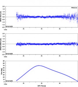
Figure 1: Pseudorange errors of IOV-3 tracking at Tanegashima, Japan, using the E1 BOC(1,1) signal (top) and the E5 AltBOC signal (center). The elevation angle over time is shown in the bottom panel.
“According to an ESA statement, FM3will continue to use binary offset carrier modulation — specifically BOC(1,1) — on the E1 Open Service signals for the time being. In contrast to this, the first pair of IOV satellites has already started to use composite binary offset carrier modulation, which offers better multipath suppression in the received signal.
“The E5 AltBOC pseudorange measurements in particular exhibit an exceptionally low noise and multipath level of better than 10 centimeters at mid- and high-elevation angles.”
After discussing and displaying some carrier-phase measurements of the Galileo FM3 E1, E5, and E6 signals, Montenbruck and Langley conclude; “This level of performance highlights the potential benefit of Galileo signals in advanced triple-frequency techniques such as undifferenced ambiguity resolution and ionospheric monitoring.”
Theoretically, the total of four Galileo IOV satellites now in medium-Earth orbit yield the minimum number needed to perform a 3D navigation fix, although no statement of initial — or even sketchy — operating capability has been issued by the European Space Agency (ESA), nor is one expected.
Antonio Tajani, vice-president of the European Commission (EC) and head of the EC directorate-general responsible for industry and entrepreneurship, continues to publicly maintain a “political objective [of] the delivery of the first services before the end of 2014,” based on 18 orbiting satellites. In a December speech, he revised the basis for that position slightly to say the civil Open Service (OS) could be declared operational with as few as 12 satellites.
The system operators had announced three dual-satellite launches in 2013, two dual-satellite launches and one four-satellite launch in 2014, hypothetically producing an operable constellation of 18 satellites by the end of the promised 2014. However, unconfirmed reports from Europe suggest that problems with manufacture of the next set of 14 Galileo satellites mean that no launches at all will take place until Q4 of 2013. Whether this will push out the service delivery date beyond 2014 or not remains open to conjecture.
Compass
Another matter open to conjecture and much speculation is whether the world will soon — or ever — see an interface control document (ICD) for China’s Compass system. More than a year ago, I wrote that “The ICD has been rumored to be available previously to receiver manufacturers within China, creating some disgruntlement among companies outside the country . . . GPS/Compass chips and receivers are being actively developed by many Chinese manufacturers and research institutes.” Indeed, conference presentations, leading to a published article in this magazine’s October issue, “What Is Achievable with the Current Compass Constellation,“ confirm that this is so.
And yet, the rest of the world neither has nor holds a Compass ICD.
The end-of-year rumor mill has kicked into gear again, though. A GNSS industry representative stationed in Shanghai, China sent this message recently to a U.S. colleague: “Latest unofficial news said that the Compass Interface Control Document (ICD) will be released on 27th this month, and will be available on the internet on 28th.”
Two British technologists backed by the U.K. Ministry of Defense have filed patents on the future interoperable GPS and Galileo signal designs that severely disrupt modernization plans for both systems and suddenly, unexpectedly place receiver manufacturers in a highly uncertain and unfavorable situation. Some of the patents have been granted in the U.K. and in Europe, and applications are pending in U.S. patent court, with a ruling expected at any time.
Companies in the United States and outside the country are being approached and asked to pay royalties, on the basis of the patent filings, for use of the European E1 Open Service signal and the modernized GPS L1C signal. Should such initiatives prevail, costs would presumably be passed along to end users of GPS and Galileo — the same taxpayers who have already paid once for the systems.
The purveyor of the royalty solicitations is Jim Ashe, vice president for sales and intellectual property at Ploughshare Innovations Ltd., Hampshire, UK. The patents, if successfully used to collect fees from satellite manufacturers or receiver manufacturers, would have a chilling effect on the use of the new interoperable signals that all parties have labored so hard, for so long, to design. They could quite possibly lead to a return to a BOC(1,1) structure for these signals, losing the benefits of MBOC.
“There’s quite an argument going on,” said one person familiar with the controversy. “Some of the methods of arguing have not been too kind.”
The Background. A great deal of work was accomplished cooperatively between the United States and the European Union (EU) to develop the landmark 2004 signal agreement that emerged from the Galileo Signal Task Force, formalizing cooperation on satellite navigation between the United States and more than two dozen European countries, including the U.K. Part of that agreement concerned a common signal structure (spectrum) for the civilian signals for both the E1 Open Service (OS) signal — the Galileo equivalent of GPS L1 — and the new U.S. GPS L1C signal to be implemented on the GPS III satellites, coming as early as 2015.
The EU said during that process, in effect, “Even though we have agreed on this, Europe wants to be able to optimize the E1 OS signal beyond the agreement on that civilian signal being a binary offset carrier BOC(1,1) signal.” Both international entities had agreed that would be the waveform or the spectrum of the new signal.
The Europeans began to evaluate methods of optimizing their signal. They had some designs called composite binary coded symbols (CBCS), a mechanism of putting a higher frequency componenent into the signal structure, and also a version called CBCS*, meaning that they found there was a bias generated by that extra signal, and so they had to invert every other one of its repetitions.
The signal structure that they were playing with was centered on a plus and a minus 5-MHz component. (Actually five times 1.023, because of the inherent clock of GPS, you can think of it as 1.023 MHz. Everyone in doing compatible or interoperable signals agreed upon that; when reference is made to 5 or 10 MHz, or an even 5 or an even 10, it means that number multiplied by 1.023).
The Europeans were were putting an additional BOC signal on top of the BOC 1,1, and it would have plus or minus 5 MHz as the centers of those two BOC peaks, and then some kind of waveform to modulate that.
The United States pushed back against that to some degree, and proposed adoption of the so-called MBOC waveform, in which case the U.S. signal was equally optimized with a concept called time-multiplexed BOC (TMBOC). The Europeans used the CBOC approach. So, very different ways of doing this. In the European way, they transmitted a continuous but very low-power BOC(6,1) term. The U.S approach transmits four BOC(6,1) chips out of every 33 chips of code (see “Future Wave” sidebar).
A chip in this case means a part of the spreading code, so each signal has its spreading codes, just like the C/A code is a spreading code, meaning a pseudorandom code modulating the carrier. L1C and E1 OS have a pseudorandom spreading code.
The U.S. approach does not put BOC(6,1) components onto the data; that’s what is commonly called MBOC. The U.S. approach is TMBOC, on the pilot carrier only, not on the data component. The European system is like two separate signals, the BOC(1,1) signal having both pilot and data, and a BOC(6,1) signal having both pilot and data. They’ve put the (6,1) into both data and pilot components.
Cue the Antagonists. Part of the task force from Europe and the United States considering the future signals’ make-up were Tony Pratt and John Owen, who works for the U.K. Ministry of Defense and whose office sponsored Pratt’s work. The two participated heavily in all these signal discussions. They stated in early meetings they planned to file patents in some areas.
“Frankly,” states one source, “people should have paid more attention when they said that, and asked ‘What do you mean, and how’s it going to work, etcetera?’ And secondly, there probably should have been a written agreement between parties that nobody will take advantage or patent any of these ideas that we are developing.”
Pratt and Owen filed a number of patents domestically, in the U.K., and and in the European Union, in 2003 and in 2006, and in other places around the world, such as Japan, Canada, and in the United States as well. Some of the U.K. and European patents have been granted. The first of some of those U.S. patents may be issued in the near future.
The original patent filings were later amended to include new claims. The new claims were much more specifically oriented toward TMBOC and CBOC, whereas the original claims were more generally oriented toward modulated methods. The claims have been modified over the years; this is fairly standard patent practice.
As a result, the original 2003 patent doesn’t necessarily read on a particular signal, but its early filing date has precedence. The claims have been updated and modified, and if the patent office issues those, as a true patent, then the new claims apply. Plenty of big patent battles have been fought over just such issues.
Once the patent is issued, a satellite or receiver manufacturer must assume that it is valid, and has only two responses to make, other than acquiescing to royalty claims. The manufacturer can either say, if building a product, “No, my product does not infringe, and I will prove that it doesn’t.’” The other choice for manufacturers is to go back into the patent office and sue the patent filer (and grantee) in the patent courts and prove that the patent was invalid in the first place that the patentee should not have been granted it.
The United States and others were taken off-guard when the U.K. company Ploughshare, which is owned and controlled by a part of the British MoD called Defense Science and Technology Laboratory (DSTL), started making claims on manufacturers. The DSTL is similar to the U.S. Defense Advance Research Products Agency (DARPA), which is credited with inventing the Internet. If taxpayer money goes into something new and interesting, it is considered in some circles legitimate to file patents on those and attempt to recover taxpayer money through royalties on that taxpayer investment. That concept is not being challenged. Questions as to whether the patents are legitimate are very much in discussion.
Ploughshare has contacted companies, saying, “If you use these signals coming from either the European satellites or the U.S. satellites, we will go after companies using these signals.” There are different patents issued, one by the European Patent Office, applying to most of the EU countries, that applies directly to the TMBOC signal, the E1 OS signal, and possibly also to Europe’s E5 signal, which is E5a and E5b; and there is also a patent for GPS III, the L1C signal.
“If you take the patent that hits TMBOC, and you take the broadest possible interpretation of that patent against receiver companies, it says: if you bring into your antenna and process that signal, whether you use all parts of it or not, for instance if you use the BOC(1,1) and not the BOC(6,1) part — then you infringe the patent. Others argue that if you don’t use both components, you don’t infringe.
“But the claim is written broadly enough that it would apply to any receiver receiving and processing the signal. Nobody says what processing means. The patent says if you receive and process the TMBOC signal, as defined in the prior claim, you infringe the patent.
“There is confusion as to whether that will apply or not apply — some people expect that it doesn’t and some people think that it might. That’s up in the air.”
George Is Getting Upset. Various factions in the United States are upset by and trying to figure out what to do about the impasse. From a government point of view, there are three paths that the U.S. government can follow:
Put pressure on the U.K. diplomatically. That would be up to the State Department to put pressure on the EU or the U.K. in particular. The EU and the continental Europeans are equally furious at the British for doing this, as far as parties in the U.S. understand. This can’t be stated as a fact but is widely understood and thought to be the case. The diplomatic approach has its limits, obviously.
Go into Europe and fight the patents in European patent court and try to prove them invalid, to invalidate the patents. Companies could do the same thing, go into various courts, whether they be U.S. or European or Japanese, and say: “Our receivers don’t infringe,” and then have to prove that to the court; or say “The whole patent should not have been allowed, and I’ll fight the legitimacy of the patent.”
Some believe — and there is controversy and anger on this point — that, just as Galileo’s IOV satellites have the capability to transmit without the BOC(6,1) component, the United States should be able to do that with the GPS III satellites as well. Because if the signal is not there, and if the receivers are therefore not designed to process the signals that are not there, then the patent no longer has any relevance.
“If we are to turn off the BOC(6,1) term for a period of time until the legal or diplomatic or other approaches worked, then we would be able to turn the BOC(6,10) term back on again, and return to the original agreed MBOC and TMBOC signals. That requires some coordination between the United States and Europe, and it requires some work to make that possible in the GPS III satellites, putting a switch in the GPS III satellites to permit the operators to turn that (6,1)BOC on and off. This is being hotly debated.”
Some parties object, stating that L1C is too important a signal to mess with, and this proposal runs the risk of slowing down the program, and/or making it more expensive. They believe strongly that the off/on switch is not the best or most far-sighted option: why should the United States be forced to change its signal design due to an illegitimate patent, and in the end wind up with a less capable system?
It is not publicly known whether the Air Force is or is not looking into that option.
During the week of June 25 there was Working Group-A meeting in Washington D.C. followed by a plenary meeting between the EU and United States. The patent controversy was presumably discussed in some fashion, but whether formally addressed or lurking in the background is unknown at this time.
“There is some naivete around this,” said the magazine’s soure. “It’s a serious threat. People think maybe they’ll only go after the high-end receivers, and maybe the royalties won’t be so bad. Ploughshare is trying to lull people into a false sense of security. The impact of this will be great unless it is defeated.”
“The L1C waveform originally was to have been a pure BOC(1,1) (a 1.023 MHz square wave modulated by a 1.023 MHz spreading code). Negotiations between the U.S. and the European Union (EU) at that time resulted in an agreement that both GPS and Galileo would use a baseline BOC(1,1) signal. However, the EU reserved the right to further optimize their signal within certain bounds. Some of the optimization proposals were known as CBCS and CBCS*. However, in further EU/US discussions it was decided that L1C and the Galileo E1 open service signal should have identically the same spectrum. This was a significant challenge because of different baseline signal structures and existing designs.
“The breakthrough came when [U.S. representative] John Betz proposed what is called MBOC. The MBOC waveform has 10/11th of its power in BOC(1,1) and 1/11th in BOC(6,1). However, L1C and E1 OS achieve this result in very different ways. The Galileo technique is called CBOC. The GPS technique is called TMBOC. Whereas Galileo has a 50/50 power split between pilot and data and includes the BOC(6,1) component in each, GPS includes the BOC(6,1) waveform only in the pilot component by modulating four of every 33 spreading code chips with a 6 MHz square wave and 31 chips with a 1 MHz square wave. With 75 percent of the power in the pilot, the result is 3/4 x 4/33 or 1/11, as required. It is likely the BOC(6,1) signal component will be ignored by consumer-grade GNSS receivers where a narrow RF bandwidth is preferred. Fortunately that is a loss of only 12 percent (0.56 dB) of the L1C pilot power. However, for commercial and professional grade receivers, the extra waveform transitions (wider Gabor bandwidth) can be used to improve code tracking signal-to-noise ratio, and with certain advanced techniques it should be possible to improve multipath mitigation. This final point depends on careful control or calibration of the transmitted code timing and symmetry.”
EGNOS and Galileo IOV Satellites Shift Right
The next EGNOS satellite, originally scheduled for a June 18 launch, now has a rise date of July 7 from Baikonur Cosmodrome in Kazakhstan. The launch was delayed by a problem with a first-stage subsystem on the Proton rocket. SES-5 is also known as Sirius 5, stemming from the development of the Sirius satellite constellation by Nordic Satellite AB, now owned by Luxembourg’s SES.
The satellite carries a transponder for the European Geostationary Navigation Overlay Service (EGNOS). The transponder is intended to eventually replace or one of those on the currently used EGNOS satellites (Inmarsat 3-F2 at 15.5 degrees west using PRN 120, Artemis at 21.5 degrees east using PRN124, and Inmarsat-4-F2 at 25 degrees east using PRN 126 and designated for industry tests).
Unlike the present L1-only EGNOS satellites, SES-5 will have transponders on both L1 and E5 frequencies similar to the Wide Area Augmentation System satellites, which broadcast on L1 and L5.
SES-5 is to be stationed at 5 degrees east longtiude.
A second SES satellite with EGNOS transponders is under construction. The SES Astra 5B satellite is scheduled for launch in the second quarter of 2013 and will be positioned at SES Astra’s 31.5 degrees east orbital position.
Role Switch. On March 22 and 23, Inmarsat-4-F2 at 25 degrees east using PRN126 and Artemis at 21.5 degrees east using PRN124 switched roles. PRN126 became an EGNOS operational signal-in-space satellite, while PRN124 became the test satellite, transmitting message type 0. PRN120 and PRN126 returned to service around 17:00 UTC on Tuesday, June 26.
According to an EGNOS service announcement dated April 3, the switch was due to the aging state of the Artemis satellite.
Galileo October Birds. According to a usually reliable source, the launch date for the second set of Galileo IOV satellites, previously announced as September 28, has been pushed back a couple of weeks to October 12.
Two British technologists backed by the U.K. Ministry of Defense have filed patents on the future interoperable GPS and Galileo signal designs that severely disrupt modernization plans for both systems and suddenly, unexpectedly place receiver manufacturers in a highly uncertain and unfavorable situation. Some of the patents have been granted in the U.K. and in Europe, and applications are pending in U.S. patent court, with a ruling expected at any time.
Companies in the United States and outside the country are being approached and asked to pay royalties, on the basis of the patent filings, for use of the European E1 Open Service signal and the modernized GPS L1C signal. Should such initiatives prevail, costs would presumably be passed along to end users of GPS and Galileo — the same taxpayers who have already paid once for the systems.
The purveyor of the royalty solicitations is Jim Ashe, vice president for sales and intellectual property at Ploughshare Innovations Ltd., Hampshire, UK. The patents, if successfully used to collect fees from satellite manufacturers or receiver manufacturers, would have a chilling effect on the use of the new interoperable signals that all parties have labored so hard, for so long, to design. They could quite possibly lead to a return to a BOC(1,1) structure for these signals, losing the benefits of MBOC.
“There’s quite an argument going on,” said one person familiar with the controversy. “Some of the methods of arguing have not been too kind.”
The Background. A great deal of work was accomplished cooperatively between the United States and the European Union (EU) to develop the landmark 2004 signal agreement that emerged from the Galileo Signal Task Force, formalizing cooperation on satellite navigation between the United States and more than two dozen European countries, including the U.K. Part of that agreement concerned a common signal structure (spectrum) for the civilian signals for both the E1 Open Service (OS) signal — the Galileo equivalent of GPS L1 — and the new U.S. GPS L1C signal to be implemented on the GPS III satellites, coming as early as 2015.
The EU said during that process, in effect, “Even though we have agreed on this, Europe wants to be able to optimize the E1 OS signal beyond the agreement on that civilian signal being a binary offset carrier BOC(1,1) signal.” Both international entities had agreed that would be the waveform or the spectrum of the new signal.
The Europeans began to evaluate methods of optimizing their signal. They had some designs called composite binary coded symbols (CBCS), a mechanism of putting a higher frequency componenent into the signal structure, and also a version called CBCS*, meaning that they found there was a bias generated by that extra signal, and so they had to invert every other one of its repetitions.
The signal structure that they were playing with was centered on a plus and a minus 5-MHz component. (Actually five times 1.023, because of the inherent clock of GPS, you can think of it as 1.023 MHz. Everyone in doing compatible or interoperable signals agreed upon that; when reference is made to 5 or 10 MHz, or an even 5 or an even 10, it means that number multiplied by 1.023).
The Europeans were were putting an additional BOC signal on top of the BOC 1,1, and it would have plus or minus 5 MHz as the centers of those two BOC peaks, and then some kind of waveform to modulate that.
The United States pushed back against that to some degree, and proposed adoption of the so-called MBOC waveform, in which case the U.S. signal was equally optimized with a concept called time-multiplexed BOC (TMBOC). The Europeans used the CBOC approach. So, very different ways of doing this. In the European way, they transmitted a continuous but very low-power BOC(6,1) term. The U.S approach transmits four BOC(6,1) chips out of every 33 chips of code (see “Future Wave” sidebar).
A chip in this case means a part of the spreading code, so each signal has its spreading codes, just like the C/A code is a spreading code, meaning a pseudorandom code modulating the carrier. L1C and E1 OS have a pseudorandom spreading code.
The U.S. approach does not put BOC(6,1) components onto the data; that’s what is commonly called MBOC. The U.S. approach is TMBOC, on the pilot carrier only, not on the data component. The European system is like two separate signals, the BOC(1,1) signal having both pilot and data, and a BOC(6,1) signal having both pilot and data. They’ve put the (6,1) into both data and pilot components.
Cue the Antagonists. Part of the task force from Europe and the United States considering the future signals’ make-up were Tony Pratt and John Owen, who works for the U.K. Ministry of Defense and whose office sponsored Pratt’s work. The two participated heavily in all these signal discussions. They stated in early meetings they planned to file patents in some areas.
“Frankly,” states one source, “people should have paid more attention when they said that, and asked ‘What do you mean, and how’s it going to work, etcetera?’ And secondly, there probably should have been a written agreement between parties that nobody will take advantage or patent any of these ideas that we are developing.”
Pratt and Owen filed a number of patents domestically, in the U.K., and and in the European Union, in 2003 and in 2006, and in other places around the world, such as Japan, Canada, and in the United States as well. Some of the U.K. and European patents have been granted. The first of some of those U.S. patents may be issued in the near future.
The original patent filings were later amended to include new claims. The new claims were much more specifically oriented toward TMBOC and CBOC, whereas the original claims were more generally oriented toward modulated methods. The claims have been modified over the years; this is fairly standard patent practice.
As a result, the original 2003 patent doesn’t necessarily read on a particular signal, but its early filing date has precedence. The claims have been updated and modified, and if the patent office issues those, as a true patent, then the new claims apply. Plenty of big patent battles have been fought over just such issues.
Once the patent is issued, a satellite or receiver manufacturer must assume that it is valid, and has only two responses to make, other than acquiescing to royalty claims. The manufacturer can either say, if building a product, “No, my product does not infringe, and I will prove that it doesn’t.’” The other choice for manufacturers is to go back into the patent office and sue the patent filer (and grantee) in the patent courts and prove that the patent was invalid in the first place that the patentee should not have been granted it.
The United States and others were taken off-guard when the U.K. company Ploughshare, which is owned and controlled by a part of the British MoD called Defense Science and Technology Laboratory (DSTL), started making claims on manufacturers. The DSTL is similar to the U.S. Defense Advance Research Products Agency (DARPA), which is credited with inventing the Internet. If taxpayer money goes into something new and interesting, it is considered in some circles legitimate to file patents on those and attempt to recover taxpayer money through royalties on that taxpayer investment. That concept is not being challenged. Questions as to whether the patents are legitimate are very much in discussion.
Ploughshare has contacted companies, saying, “If you use these signals coming from either the European satellites or the U.S. satellites, we will go after companies using these signals.” There are different patents issued, one by the European Patent Office, applying to most of the EU countries, that applies directly to the TMBOC signal, the E1 OS signal, and possibly also to Europe’s E5 signal, which is E5a and E5b; and there is also a patent for GPS III, the L1C signal.
“If you take the patent that hits TMBOC, and you take the broadest possible interpretation of that patent against receiver companies, it says: if you bring into your antenna and process that signal, whether you use all parts of it or not, for instance if you use the BOC(1,1) and not the BOC(6,1) part — then you infringe the patent. Others argue that if you don’t use both components, you don’t infringe.
“But the claim is written broadly enough that it would apply to any receiver receiving and processing the signal. Nobody says what processing means. The patent says if you receive and process the TMBOC signal, as defined in the prior claim, you infringe the patent.
“There is confusion as to whether that will apply or not apply — some people expect that it doesn’t and some people think that it might. That’s up in the air.”
George Is Getting Upset. Various factions in the United States are upset by and trying to figure out what to do about the impasse. From a government point of view, there are three paths that the U.S. government can follow:
Put pressure on the U.K. diplomatically. That would be up to the State Department to put pressure on the EU or the U.K. in particular. The EU and the continental Europeans are equally furious at the British for doing this, as far as parties in the U.S. understand. This can’t be stated as a fact but is widely understood and thought to be the case. The diplomatic approach has its limits, obviously.
Go into Europe and fight the patents in European patent court and try to prove them invalid, to invalidate the patents. Companies could do the same thing, go into various courts, whether they be U.S. or European or Japanese, and say: “Our receivers don’t infringe,” and then have to prove that to the court; or say “The whole patent should not have been allowed, and I’ll fight the legitimacy of the patent.”
Some believe — and there is controversy and anger on this point — that, just as Galileo’s IOV satellites have the capability to transmit without the BOC(6,1) component, the United States should be able to do that with the GPS III satellites as well. Because if the signal is not there, and if the receivers are therefore not designed to process the signals that are not there, then the patent no longer has any relevance.
“If we are to turn off the BOC(6,1) term for a period of time until the legal or diplomatic or other approaches worked, then we would be able to turn the BOC(6,10) term back on again, and return to the original agreed MBOC and TMBOC signals. That requires some coordination between the United States and Europe, and it requires some work to make that possible in the GPS III satellites, putting a switch in the GPS III satellites to permit the operators to turn that (6,1)BOC on and off. This is being hotly debated.”
Some parties object, stating that L1C is too important a signal to mess with, and this proposal runs the risk of slowing down the program, and/or making it more expensive. They believe strongly that the off/on switch is not the best or most far-sighted option: why should the United States be forced to change its signal design due to an illegitimate patent, and in the end wind up with a less capable system?
It is not publicly known whether the Air Force is or is not looking into that option.
During the week of June 25 there was Working Group-A meeting in Washington D.C. followed by a plenary meeting between the EU and United States. The patent controversy was presumably discussed in some fashion, but whether formally addressed or lurking in the background is unknown at this time.
“There is some naivete around this,” said the magazine’s soure. “It’s a serious threat. People think maybe they’ll only go after the high-end receivers, and maybe the royalties won’t be so bad. Ploughshare is trying to lull people into a false sense of security. The impact of this will be great unless it is defeated.”
“The L1C waveform originally was to have been a pure BOC(1,1) (a 1.023 MHz square wave modulated by a 1.023 MHz spreading code). Negotiations between the U.S. and the European Union (EU) at that time resulted in an agreement that both GPS and Galileo would use a baseline BOC(1,1) signal. However, the EU reserved the right to further optimize their signal within certain bounds. Some of the optimization proposals were known as CBCS and CBCS*. However, in further EU/US discussions it was decided that L1C and the Galileo E1 open service signal should have identically the same spectrum. This was a significant challenge because of different baseline signal structures and existing designs.
“The breakthrough came when [U.S. representative] John Betz proposed what is called MBOC. The MBOC waveform has 10/11th of its power in BOC(1,1) and 1/11th in BOC(6,1). However, L1C and E1 OS achieve this result in very different ways. The Galileo technique is called CBOC. The GPS technique is called TMBOC. Whereas Galileo has a 50/50 power split between pilot and data and includes the BOC(6,1) component in each, GPS includes the BOC(6,1) waveform only in the pilot component by modulating four of every 33 spreading code chips with a 6 MHz square wave and 31 chips with a 1 MHz square wave. With 75 percent of the power in the pilot, the result is 3/4 x 4/33 or 1/11, as required. It is likely the BOC(6,1) signal component will be ignored by consumer-grade GNSS receivers where a narrow RF bandwidth is preferred. Fortunately that is a loss of only 12 percent (0.56 dB) of the L1C pilot power. However, for commercial and professional grade receivers, the extra waveform transitions (wider Gabor bandwidth) can be used to improve code tracking signal-to-noise ratio, and with certain advanced techniques it should be possible to improve multipath mitigation. This final point depends on careful control or calibration of the transmitted code timing and symmetry.”
A subsidiary of the UK Ministry of Defence has been granted a UK patent on the MBOC signal design, which was a product of lengthy and cooperative negotiations between U.S. and European scientists.
The UK patent, taken in the names of two UK scientists participating in the project, is being used by a legal firm to demand royalty fees from receiver manufacturers. This is causing considerable controversy. GPS World will provide more context and details in an upcoming story.
Performance of Multiplexed Binary Offset Carrier Modulations for Modernized GNSS Systems
By E. Simona Lohan, Mohammad Z. H. Bhuiyan, and Heikki Hurskainen
A candidate for modernized GNSS civil signals in the L1/E1 band was BOC(1,1), a binary-offset-carrier signal with a “split spectrum” that has negligible impact on the existing GPS signals. However, a signal with better acquisition capabilities and improved multipath performance (while still compatible with the existing GPS signals) is a multiplexed BOC modulation, MBOC(6,1,1/11). The MBOC spectrum can be achieved by following one of several different signal-construction paths with some resulting differences in how a receiver tracks the signal and its associated performance.
INNOVATION INSIGHTS by Richard Langley
IN GEOFFREY CHAUCER’S 1391 ESSAY, A Treatise on the Astrolabe (one of the earliest known instruction manuals in English), he says (with modern spelling) “Right as diverse paths lead the folk the right way to Rome.” He was talking about the use of English rather than Latin or another language to convey the same information. And we now commonly use the shortened version of this expression — all roads lead to Rome — to express the sentiment that a particular problem can be solved in different ways.
So it was with the decision by the United States and Europe to use a common, interoperable signal for the new GPS III civil service and the Galileo Open Service on the L1/E1 frequency of 1575.42 MHz. The road to “Rome” was tedious, long, and a little bumpy at times. A number of studies and a lot of rhetoric centered on how to make the new signal compatible with the legacy GPS L1 signals, the C/A-code and the P(Y)-code, as well as the modernized GPS military signal on L1, the M-code.
A similar compatibility issue had been solved when the M-code was added to the legacy GPS signals, starting with the Block IIR-M satellites. The M-code is a binary-offset-carrier (BOC) signal — a split spectrum signal — that places most of its power near the edges of the allocated GPS frequency bands, thereby having negligible impact on the legacy signals. The M-code modulation, designated BOC(10.23,5.115) and commonly abbreviated BOC(10,5), uses a subcarrier frequency of 10.23 MHz and a spreading code rate of 5.115 megachips per second to achieve the desired spectral separation. This design provides military users with an improved signal with little impact on civil users.
Similar approaches were initially proposed for the new GPS L1C and Galileo E1/L1 OS signals with a BOC(1,1) modulation initially agreed on. However, further studies showed that a signal with better acquisition capabilities and improved multipath performance (while still compatible with the existing GPS signals) was a multiplexed BOC modulation, MBOC(6,1,1/11), formed by multiplexing a wideband signal, BOC(6,1), with a narrow-band signal, BOC(1,1), in such a way that 1/11th of the power is allocated, on average, to the high frequency component. Such a signal has the added benefit that one can choose whether to make use of just the low-frequency component in, say, a simple “mass market” receiver or also use the high-frequency component for more demanding applications.
It turns out that the agreed-upon MBOC spectrum can be achieved by following one of several different signal-construction paths with some resulting differences in how a receiver tracks the signal and its associated performance. In this month’s column, we take a look at some of the options.
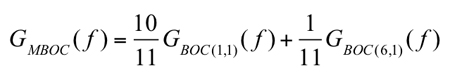
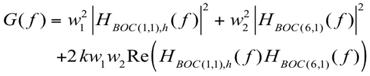
In July 2007, the United States and Europe announced agreement on the use of the multiplexed binary offset carrier (MBOC) modulation as a common baseline for Galileo Open Service signals in the E1 band and GPS L1C signals in the L1 band. According to the most recent Galileo Signal-In-Space Interface Control Document (SIS-ICD; see Further Reading), the MBOC power spectral density (PSD) has been fixed to
(1)
where GBOC(m,n)(f) is the normalized PSD of a BOC(m,n)-modulated pseudorandom noise (PRN) code with sine phasing. The indices m and n are related to the sub-carrier frequency, fsc, and the chip frequency, fc, via m = fsc/frefand n = fc/fref, respectively; fref = 1.023 MHz is the reference C/A-code frequency, and NB = 2fsc/fc = 2m/n is the BOC modulation index.
The MBOC PSD is obtained by taking the data and pilot channels together. The data and pilot channels can use, independently, one of the following modulations: composite binary offset carrier (CBOC) or time-multiplexed binary offset carrier (TMBOC) modulations. CBOC and TMBOC, in turn, have several variants. Since the data and pilot channels are typically processed independently, it is important to understand the differences between various CBOC and TMBOC modulations and this is the primary goal of this article. There are several possible ways to achieve a PSD as given in Equation (1) and they are based on combining the data and pilot channels in the Galileo and modernized GPS systems. The main modulation types for pilot or data channels that can be used in order to achieve (when combined) the MBOC PSD can be summarized as follows:
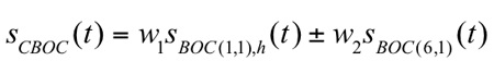
1. The CBOC method: CBOC is formed via a weighted sum or difference of BOC(1,1)- and BOC(6,1)-modulated code symbols (where the BOC(1,1) part is passed through a delay block in order to match the rate of the BOC(6,1) part) as defined in Equation (2):
(2)
where sBOC(1,1),h is the up-sampled BOC(1,1)-modulated code (that is, the code provided at the same rate as the sBOC(6,1) signal), sBOC(6,1) is the BOC(6,1)-modulated code, and w1 and w2 are amplitude weighting factors, chosen in such a way to match (as closely as possible, when both data and pilot channels are considered) the PSD of Equation (1), with w12 + w22 = 1. When the two right-hand terms are added in Equation (2), CBOC(+) is formed; when subtracted, CBOC(–) is formed. A third alternative for CBOC implementation is to use the CBOC(+/–) approach, where the odd-numbered chips are CBOC(+)-modulated and the even chips are CBOC(–)-modulated. The current Galileo SIS-ICD uses a CBOC(+) variant (also called CBOC in-phase) for the E1-B data channel and a CBOC(–) variant (also called CBOC anti-phase) for the E1-C data-less (or pilot) channel.
2. The time-multiplexed BOC (TMBOC) method: the whole signal is divided into blocks of N code symbols with M (<N) code symbols sine-BOC(1,1)-modulated, while N-M code symbols are sine-BOC(6,1)-modulated. The typical shorthand notation for this variety of TMBOC would be TMBOC(6,1,(N-M)/N), referring to the sine-BOC(6,1) component of the signal. This time-domain division may be applied for both pilot and data channels, individually. The choice of the N and M parameter values depends on the desired power percentage of the pilot channel with respect to the data channel. We have shown in earlier work (see Further Reading) that, from the point of view of the MBOC autocorrelation function, TMBOC and CBOC(+) implementations are equivalent, as long as the weights are related to the N and M values using w1 = √(M/N) and w2 = √((N-M)/N). Various TMBOC implementations exist according to the values chosen for N and M and according to whether the BOC(1,1) code symbols are in phase or out of phase with the BOC(6,1) code symbols. For example, for a 50-percent/50-percent power split between the pilot and data channels using in-phase code symbols, M = 9 and N = 11 (that is, TMBOC(6,1,2/11) is used), while for a 75-percent/25-percent power split between the pilot and data channels (again, using in-phase code symbols), M = 29 and N = 33 (that is, TMBOC(6,1,4/33) is used).
A major difference between CBOC and TMBOC signals is that CBOC signals have four different levels (as a weighted sum or difference of two sub-carriers), while TMBOC signals have only two levels. The impact of these differences in the tracking stage of a receiver has been analyzed, for example, by a team of researchers led by Olivier Julien (see Further Reading). They showed that an optimal CBOC receiver should generate a local replica that also has four levels, resulting in a replica encoded on more than just one bit. This complicates the CBOC receiver architecture, compared to TMBOC 1-bit receiver architectures. In terms of performance, a CBOC(–) receiver proved to have the same delay-tracking variance performance as a TMBOC(6,1,4/33) receiver and both slightly outperform a TMBOC(6,1,1/11) receiver. And considering multipath error performance, a TMBOC(6,1,4/33) receiver was shown to give the best performance, followed very closely by a CBOC(–) receiver. Our research extends this earlier study.
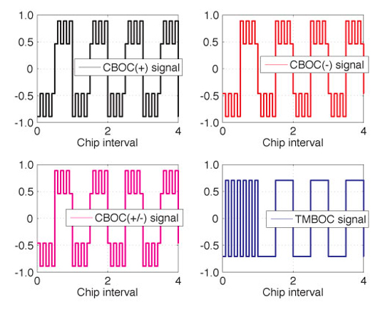
Examples of CBOC and TMBOC waveforms are shown in Figure 1. Here, w1 = (10/11) and the TMBOC waveform has every first chip BOC(6,1)-modulated (inside blocks of 11 chips). In the figure, only the first five modulated chips are shown for clarity.
Figure 1. Example of MBOC waveforms for a PRN sequence [1, -1, 1, -1, -1].Our article addresses the following issues: First, we analyze the spectral differences between various CBOC and TMBOC modulations in terms of their effect on receiver performance. Secondly, we look at the navigation data error probability, the tracking error variance in the presence of noise, and the robustness of the signal in the presence of multipath and bandwidth limitations of MBOC variants, by taking into account the spectral differences between the different variants. Thirdly, we justify the choice of CBOC(+) for data channels and CBOC(–) for pilot channels in the Galileo SIS-ICD in terms of these receiver performance criteria.
Spectral Differences of CBOC/TMBOC Modulations
The spectral differences refer to the differences in the PSD of various waveforms. We recall that the PSD is the Fourier transform of the CBOC/TMBOC autocorrelation function. CBOC/TMBOC signals are formed from the convolution of PRN code waveforms, CBOC/TMBOC modulation waveforms, and navigation data (when present). If the same PRN code is used for the BOC(1,1) and BOC(6,1) modulations, some cross-correlation terms appear in the autocorrelation function, which will also appear in the frequency spectrum. Indeed, following the model, after straightforward derivations, we obtain the generic CBOC/TMBOC PSD as:
(3)
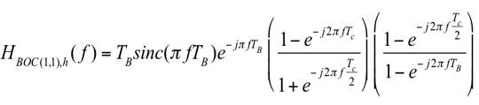
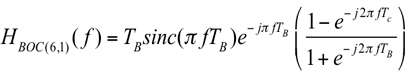
where HBOC(1,1),h(f) and HBOC(6,1)(f) are the following Fourier transforms of the modulation waveforms:
(4)
(5)
Above, TB = TC/12 is the BOC(6,1) sub-interval and sinc(x) = sin(x)/x. The formula given in Equation (3) covers all CBOC/TMBOC cases: k = +1 for CBOC(+) and TMBOC, k = –1 for CBOC(–), and k = 0 for CBOC(+/–), respectively. Equation (3) characterizes either the pilot channel’s PSD or the data channel’s PSD. In order to achieve the PSD of Equation (1), data and pilot channels should be combined. For example, if k = 0, any combination of data and pilot channels is possible in order to attain the PSD. If k ≠ 0, then the data channel should use in-phase combining (k = +1) and the pilot channel should use anti-phase combining (k = –1) or vice versa.
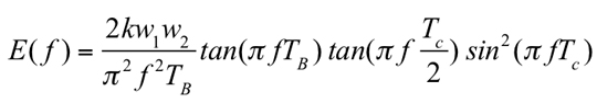
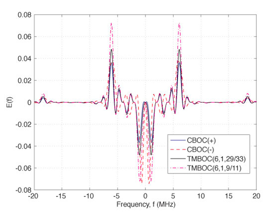
Now, if we take as a reference the PSD of CBOC(+/–) (which, incidentally, is also the PSD of Equation (1)), the spectral differences between the other CBOC/TMBOC modulations and CBOC(+/–) are quantized by the following equation:
(6)
Examples of spectral difference between CBOC(+/–) and each of the following modulations: CBOC(–), CBOC(+), and TMBOC(6,1,(N-M)/N) and each of the following modulations: CBOC(–), CBOC(+), and TMBOC(6,1,(N-M)/N), respectively, are shown in Figure 2. Clearly, these differences are very small.
Figure 2. Examples of PSD spectral differences (linear scale) between various CBOC/TMBOC implementations and CBOC(+/-) assuming an MBOC receiver.
Impact on System Performance
As mentioned before, pilot and data channels typically use different CBOC/TMBOC modulations, in order to achieve an overall PSD as described by Equation (1). Now, based on the derivations we have presented so far, the following questions can be addressed: Which are the most suitable modulations (among the four discussed here; namely, CBOC(+), CBOC(–), CBOC(+/–), and TMBOC) to be used for a pilot channel and for a data channel, respectively; and how will the differences in the PSDs affect the error probability of the decoded signal and the tracking performance of each channel?
Uncoded Error Probability and Fractional Out-of-Band Energy. Data and pilot channels are usually processed independently and then combined (for example, non-coherently) in order to perform the line-of-sight (LOS) signal delay estimation and the navigation data detection. Since different CBOC or TMBOC modulations can be used for the data and pilot channels, one question to be addressed here is what is the most suitable modulation type. Additionally, the carrier-to-noise-density ratio (C/N0) deterioration when another modulation type is employed is also important. These two issues are addressed in this section.
One important spectral parameter that allows us to answer the question about error probability in the decoded data is the so-called fractional out-of-band energy (FOBE), which tells us about the fraction of the signal power remaining outside a certain double-sided bandwidth, Bw. FOBE is related to the power containment factor, used by some authors, via (1 – FOBE(Bw)). Clearly, FOBE depends on the signal modulation type. The higher FOBE is, the greater the deterioration of the signal energy we have after the receiver bandwidth limiting filters, and thus the higher error probability of the decoded signal we have. From the data-channel point of view, correctly decoding the navigation data is very important and therefore, low FOBE is the most important characteris
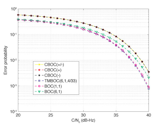
tic when choosing the modulation type. The bit error probability in decoding a binary signal, such as a BOC or MBOC signal, can be computed by taking into account the signal energy deterioration due to filtering. Using the basic formula for computing the bit error probability in decoding a 2-level signal (in the cases of BOC or TMBOC modulation) or a 4-level signal (in the case of CBOC modulation), we can compare the performance of various TMBOC and CBOC modulations in terms of error probability of the decoded data bits, as shown in Figure 3. Clearly, the error probability criterion is more important for a data channel than for a pilot channel. Sine-BOC(1,1) and BOC(6,1) modulations are included in the comparison of Figure 3 as benchmarks. A double-sided bandwidth of 24.552 MHz was considered here, following the choice in the Galileo SIS-ICD.
Figure 3. Detection error probability for CBOC/TMBOC-modulated signals with a 24.552 MHz double-sided bandwidth.
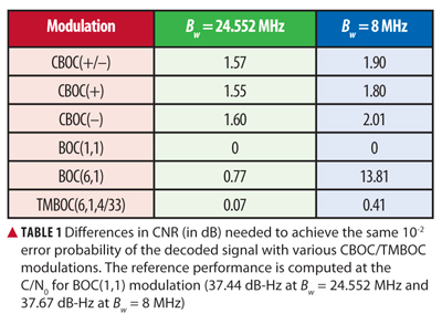
As seen in Figure 3, in terms of the error probability of the decoded signal, BOC(1,1) modulation gives the best results, followed closely by TMBOC(6,1,4/33). In order to achieve an error probability of 10-2, the CNR differences shown in Table 1 are needed for the different modulation types. From Table 1, it can be seen that, among CBOC modulations, the CBOC(+) modulation is the best option from the point of view of decoding the data, and, therefore, it makes it a suitable option for data channels, as chosen in the Galileo SIS-ICD. We remark that the huge CNR gap for BOC(6,1) at Bw = 8 MHz is due to the fact that the power containment of a BOC(6,1) signal is very poor at such a low bandwidth.
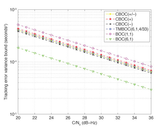
Gabor Bandwidth and Tracking Error Variance. Another important spectral parameter of interest in this analysis is the root-mean-square (RMS) or Gabor bandwidth. A larger RMS or Gabor bandwidth permits a higher accuracy against thermal noise and the tracking accuracy is approximately inversely proportional to the RMS bandwidth. The code-tracking error variance is an important parameter when trying to achieve accurate location estimates. Indeed, a Cramér-Rao lower bound (CRLB) on the tracking error variance has been derived by other researchers. Following the derivation for CRLB on the tracking error variance, we can also compare the performance of various CBOC and TMBOC modulations, as presented in Figure 4. Clearly, this criterion is more important for a pilot channel than for a data channel. A double-sided receiver bandwidth of 24.552 MHz was considered here.
Figure 4. Cramér-Rao lower bound on tracking error variance (in seconds2) for CBOC/TMBOC-modulated signals with a 24.552 MHz double-sided bandwidth.
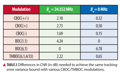
In terms of the tracking error variance bound, which linearly decreases with the CNR (on a dB scale), the CNR differences between various modulations are shown in TablE 2 for a 4-Hz tracking-loop bandwidth. Clearly, from Table 2, CBOC modulations are better in terms of tracking error variance than TMBOC modulation, and, among the CBOC variants, CBOC(–) has the best performance. This justifies the fact that the Galileo SIS-ICD has chosen the CBOC(–) as the best option for pilot channels. We can also see in Table 2 that the bandwidth limitation has an important effect on the tracking error bounds, as expected. At low receiver bandwidth (such as 8 MHz), the differences between various modulations are rather small, while at high or infinite bandwidths, BOC(6,1) modulation is by far the best option, followed by CBOC(–) with a 1.69 dB gap in CNR (that is, CBOC(–) requires an additional 1.69 dB in order to achieve the same tracking error performance as BOC(6,1)).
Multipath Error Envelope. The typical procedure for evaluating the performance of a multipath-mitigation technique is via the multipath error envelope (MEE). The MEE curves are obtained for two extreme phase variations of a multipath signal with respect to the LOS component while varying the multipath (that is, second path) delays from 0 to 1.2 chips at maximum, since the multipath errors become less significant after that. The upper multipath error envelope can be obtained when the paths are in-phase (that is, 0° phase difference) and the lower multipath error envelope when the paths are out-of-phase (that is, 180° phase difference). In MEE analysis, several simplifying assumptions are usually made in order to distinguish the performance degradation caused by the multipath only. Such assumptions include zero additive white Gaussian noise, ideal infinite-length PRN codes, zero residual Doppler shift, and zero initial code-delay error.
The MEE curves are generated here for different variants of MBOC implementation. The multipath performance of these MBOC variants with a BOC(1,1)-modulated reference receiver is also presented. In the MEE generation, the second path amplitude was fixed at 3 dB lower than the LOS component. The MEE curves were generated for a 24.552 MHz double-sided bandwidth. The narrow early-minus-late (nEML) correlator with an early-late correlator spacing of 0.0833 chips was used here as a tool for evaluating the performance of the different MBOC variants in the presence of multipath. The nEML is based on the idea of narrowing the spacing between the early and late correlator pair, where the choice of correlator spacing depends on the receiver’s available front-end bandwidth along with the associated sampling frequency.
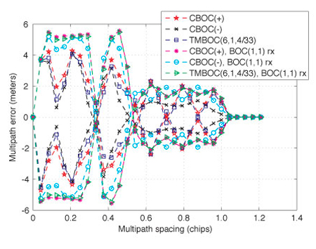
MEE curves are shown for all of the examined MBOC variants in Figure 5. It can be observed from the figure that CBOC(–) has the best multipath mitigation performance followed by the TMBOC(6,1,4/33) and CBOC(+) variants. A similar conclusion can be drawn when a BOC(1,1) reference receiver is used instead of the respective MBOC reference receiver. However, from Figure 5, it is obvious that there is a moderate performance degradation when a BOC(1,1) reference receiver is used instead of the respective MBOC version, as expected intuitively.
Figure 5. Multipath error envelope curves for a narrow early-minus-late correlator with a 24.552 MHz double-sided bandwidth.
Simulation Results in Multipath Fading Channel
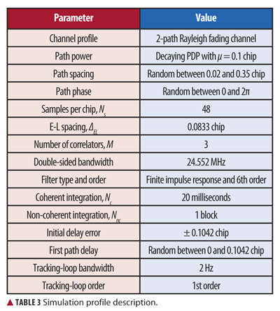
Simulations have been carried out in closely spaced multipath scenarios for different MBOC variants with a finite front-end bandwidth. The simulation profile is summarized in Table 3. A Rayleigh fading channel model is used in the simulation, where the number of channel paths is fixed to two. The successive path separation is random between 0.02 and 0.35 chips. The channel paths are assumed to obey a decaying power delay profile (PDP).
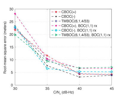
The received signal duration is 0.8 seconds for each particular C/N0 level. The tracking errors are computed after each NcNnc-milliseconds interval (in this case, NcNnc = 20 milliseconds). In the final statistics, the first 600 milliseconds are ignored in order to remove the initial error bias that may come from the delay difference between the received signal and the locally generated reference code. Therefore, for the above configuration, the left-over tracking errors after 600 milliseconds are mostly due to the effect of multipath only. We ran the simulations for 1,000 statistical points, for each C/N0 b> level. The RMS error (RMSE) of the delay estimates can be plotted in meters, by using the relationship RMSEm = RMSEchips•c•Tc, where c is the speed of light, Tc is the chip duration, and RMSEchips is the RMSE in chips. An RMSE versus C/N0 plot for the given multipath channel profile is shown in Figure 6.
As seen in the figure, the CBOC(–) reference receiver has the best multipath mitigation performance under a good
C/N0 (that is, 40 dB-Hz and higher) followed by the other two MBOC variants (CBOC(+) and TMBOC(6,1,4/33)), which exhibit almost similar performance. A similar conclusion can be drawn for the BOC(1,1) reference receiver, where the CBOC(–)-modulated transmitted signal with BOC(1,1) reference receiver showed the best multipath mitigation performance among all three of the studied MBOC variants. In Figure 6, we observe that the small performance deterioration caused by use of a BOC(1,1) reference receiver is visible only under good C/N0 conditions (that is, 40 dB-Hz and higher).
Figure 6. Root-mean-square error versus carrier-to-noise-density ratio for different MBOC variants in a two-path fading channel with 24.552 MHz double-sided bandwidth.
Conclusions
This article discusses the spectral differences between CBOC and TMBOC modulations and their impact on system performance. The exact frequency-domain form of the PSD for CBOC and TMBOC waveforms has been shown and the impact on tracking error variance bounds and on the error probability of the demodulated signal has been discussed. In addition, the multipath mitigation performances of different MBOC variants were presented in terms of RMSE and multipath error envelopes. It was shown that the CBOC(–) variant is the best variant in terms of multipath mitigation and tracking error variance, while TMBOC behaves better than CBOC in terms of error probability of the demodulated data. We also showed that the spectral differences and the differences between CBOC and TMBOC variants in terms of the two considered performance criteria are rather small, especially when the receiver bandwidth is not very high, and, therefore, several variants of MBOC can indeed be used for design and research purposes.
Acknowledgments
The research leading to the results presented in this article received funding from the European Union’s Seventh Framework Programme (FP7/2007-2013) under grant agreement number 227890 (the Galileo-Ready Advanced Mass Market Receiver–GRAMMAR–project). This research work has also been supported by the Academy of Finland and by the Tampere Doctoral Programme in Information Science and Engineering. Particular thanks are also addressed to Stephan Sand from the German Aerospace Center (DLR), Institute of Communications and Navigation, for his useful comments.
Elena Simona Lohan has been an adjunct professor in the Department of Communications Engineering at Tampere University of Technology (TUT) in Hervanta, Finland, since 2007. She obtained her Ph.D. degree in wireless communications from TUT. She also graduated with an M.Sc. in electrical engineering from “Politehnica” University of Bucharest, and with a diplôme d’études approfondies in econometrics from Ecole Polytechnique, Paris. Lohan is currently leading the research activities in signal processing for wireless communications in the Department of Communications Engineering at TUT.
Mohammad Zahidul H. Bhuiyan is a researcher in the Department of Communications Engineering at TUT. His main research areas are multipath mitigation and software receiver design for satellite-based positioning applications.
Heikki Hurskainen received an M.Sc. degree in electrical engineering and a doctoral degree in computing and electrical engineering from TUT in 2005 and 2009, respectively. Currently, Hurskainen is a senior research scientist in TUT’s Department of Computer Systems where he works on satellite navigation research projects.
Navstar GPS Space Segment/User Segment L1C Interfaces, Rev. A, Interface Specification, IS-GPS-800A, prepared by Science Applications International Corporation, El Segundo, California for the Global Positioning System Wing, Systems Engineering and Integration, Los Angeles Air Force Base, California, June 2010.
• Binary Offset Carrier Modulation
“Low Complexity Unambiguous Acquisition Methods for BOC-modulated CDMA Signals” by E.S. Lohan, A. Burian, and M. Renfors in International Journal of Satellite Communications and Networking, Vol. 26, No. 6, 2008, pp. 503–522, doi: 10.1002/sat.922.
“Binary-Offset-Carrier Modulation Techniques with Applications in Satellite Navigation Systems” by E.S. Lohan, A. Lakhzouri, and M. Renfors in Wireless Communications and Mobile Computing, Vol. 7, No. 6, 2007, pp. 767–779, doi: 10.1002/wcm.407.
“Overview of the GPS M Code Signal” by B.C. Barker, J.W. Betz, J.E. Clark, J.T. Correia, J.T. Gillis, S. Lazar, K.A. Rehborn, and J.R. Straton, III, in Proceedings of 2000: Navigating into the New Millennium, the 2000 National Technical Meeting of The Institute of Navigation, Anaheim, California, January 26–28, 2000, pp. 542–549.
“The Offset Carrier Modulation for GPS Modernization” by J.W. Betz, in Proceedings of Vision 2010: Present and Future, the 1999 National Technical Meeting of The Institute of Navigation and 19th Biennial Guidance Test Symposium, San Diego, California, January 25–27, 1999, pp. 639-648.
• Multiplexed Binary Offset Carrier Modulation Implementations and Comparisons
“Future Wave: L1C Signal Performance and Receiver Design” by T.A. Stansell, K.W. Hudnut, and R.G. Keegan in GPS World, Vol. 22, No. 4, April 2011, pp. 30–36,41.
“Analytical Performance of CBOC-modulated Galileo E1 Signal Using Sine BOC(1,1) Receiver for Mass-market Applications” by E.S. Lohan, in Proceedings of PLANS 2010, IEEE/ION Position Location and Navigation Symposium, Indian Wells, California, May 4–6, 2010, pp. 245–253, doi: 10.1109/PLANS.2010.5507207.
“MBOC and BOC(1,1) Performance Comparison” by N. Hoult, L.E. Aguado, and P. Xia in The Journal of Navigation, Vol. 61, No. 4, October 2008, pp. 613–627, doi: 10.1017/S0373463308004918.
“The MBOC Modulation: A Final Touch for the Galileo Frequency and Signal Plan” by J.A. Avila-Rodriguez, G.W. Hein, S. Wallner, J.L. Issler, L. Ries, L. Lestarquit, A. De Latour, J. Godet, F. Bastide, T. Pratt, and J. Owen in Inside GNSS, Vol. 2, No. 6, Se
ptember-October 2007, pp. 43–58.
“Two for One: Tracking Galileo CBOC Signal with TMBOC” by O. Julien, C. Macabiau, J.L. Issler, and L. Ries in Inside GNSS, Vol. 2, No. 3, Spring 2007, pp. 50–57.
“MBOC: The New Optimized Spreading Modulation Recommended for Galileo L1 OS and GPS L1C” by G.W. Hein, J.A. Avila-Rodriguez, S. Wallner, J.W. Betz, C.J. Hegarty, J.J. Rushanan, A.L. Kraay, A.R. Pratt, S. Lenahan, J. Owen, J.L. Issler, and T.A. Stansell in Inside GNSS, Vol. 1, No. 4, May-June 2006, pp. 57–65.
• Gabor Bandwidth and Cramér-Rao Bound
Spread Spectrum Systems for GNSS and Wireless Communications by J.K. Holmes, published by Artech House, Inc., Norwood, Massachusetts, 2007.
“A Family of Split Spectrum GPS Civil Signals” by J.J. Spilker, Jr., E.H. Martin, and B.W. Parkinson, in Proceedings of ION GPS-98, the 11th International Technical Meeting of the Satellite Division of The Institute of Navigation, Nashville, Tennessee, September 15–18, 1998, pp. 1905–1914.
• Narrow Early-Minus-Late Correlation
“Extended Theory of Early-Late Code Tracking for a Bandlimited GPS Receiver” by J.W. Betz and K.R. Kolodziejski in Navigation: Journal of the Institute of Navigation, Vol. 47, No. 3, 2000, pp. 211–226.