Enables building stakeholders to take accurate measurements based on point clouds
The latest release of the NavVis IndoorViewer 3D building visualization software features a new tool that lets building stakeholders take highly accurate measurements based on point clouds in the realistic 360° image view.
NavVis, global provider of indoor spatial intelligence technology and enterprise solutions, announces the release of NavVis IndoorViewer 2.6. This major software release includes a new measurement tool that lets users take highly accurate measurements based on point clouds in realistic browser-based digital buildings.
This release also makes additional features available to structured e57 point cloud files, including automatically generating highly detailed floor plans and routing.
NavVis IndoorViewer is a popular deliverable among building stakeholders without the technical expertise to work with point clouds and modeling software, thanks to the realistic digital buildings and intuitive interface.
One of the features that has proven to be useful among users across multiple industries is the measurement tool. It enables users to take measurements remotely on any device, saving time otherwise spent traveling to the site.
The release of version 2.6 of NavVis IndoorViewer marks a major advance in the accuracy of virtual measurement tools. The tool has been redesigned to overcome two of the biggest problems with virtual measurement tools – accuracy and usability.
On the one hand, point cloud measurements are quite accurate. But often these software tools are not accessible or even usable for a wide range of building stakeholders who lack the expertise in working with point clouds. If, on the other hand, the tool uses images or even meshes, which are much more user-friendly than point clouds, the tools are usually not reliable enough to produce accurate results.
The new measurement tool in NavVis IndoorViewer combines the best of both worlds, thanks to a patent-pending magnifying feature that appears when taking measurements in the realistic 360° view. The magnifying feature reveals the exact section of the point cloud behind the image and lets users pick the point cloud point as the basis for a measurement while benefiting from the intuitive interface of the fully immersive walkthrough.
“When redesigning the measurement tool in NavVis IndoorViewer, we wanted to make sure that a wide range of stakeholders in every industry that works with built environments could benefit from the accuracy of point clouds when taking virtual measurements,” said Georg Schroth, NavVis CTO. “We are confident that the new magnifying feature in NavVis IndoorViewer achieves our goal. Now even stakeholders that are unfamiliar with point clouds have an easy, intuitive way to take measurements based on this highly accurate real world data.”
In addition to making strides in the accuracy of remote measurements, the interface of the tool has also been fully redesigned. This includes a new slider function that lets users view the 2D floor plan and 3D walkthrough side-by-side or move from one view to the other.
The dual view provides an overview of the entire building so that users can easily locate an asset or area while also viewing the location in the realistic 360° view. The fully immersive walkthrough makes it possible to virtually move through the area being measured or inspect the asset, as if the user were on site. Measurements being taken show up in both views.
The release of NavVis IndoorViewer 2.6 also introduces new feature support for e57 point cloud files captured by static scanners. Previous NavVis IndoorViewer releases have included a popular feature that lets laser scanning professionals upload structured e57 point cloud files and automatically generate realistic, fully immersive 360° walkthroughs that can be published and shared with clients as a web-based link.
With the release of NavVis IndoorViewer 2.6, two popular features that were previously only compatible with scan data captured by NavVis hardware are now available for point clouds uploaded as structured e57 files. The first is the generation of a navigation graph, which makes it possible to turn static scans into a fully immersive indoor routing tool. The second is the automatic generation of highly detailed floor plans. Now point cloud files uploaded as structured e57 files can be turned into digital floor plans in a few clicks.
A roundup of recent products in the GNSS and inertial positioning industry from the April 2019 issue of GPS World magazine.
OEM
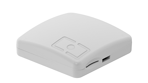
GNSS receiver
With embedded 9-DOF IMU
Photo: Rokubun
The Argonaut GNSS receiver is able to provide geo-location with real-time accuracy of 2 meters and off-line accuracy better than 0.4 meters using Argonaut PaaS. This is possible because GNSS raw measurements, together with inertial measurement unit (IMU) nine-degrees-of-freedom (9-DOF) measurements, are stored for offline GNSS processing (PPK, RTK, DGNSS). Argonaut will also register external events such as camera triggers within microsecond resolution and decimetric geo-location accuracy. The embedded IMU allows for an increased rate of navigation fixes as well as robust solutions in scenarios with impaired GNSS availability. Rokubun, rokubun.cat
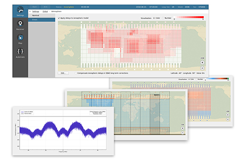
Galileo AltBOC addition
Plus atmospheric corrections
Photo: Skydel Solutions
SDX GNSS simulator update version 19.1 adds Galileo AltBOC signal generation, new atmospheric errors, SBAS improvements and SV antenna patterns. SDX users licensed with the Galileo E5 signal will be able to generate 8 Phase Shift Keying (8-PSK) constant envelope AltBOC after upgrading to SDX 19.1. Version 19.1 also adds a new error type to all SDX users: atmospheric delays. These errors can be compensated for with the SBAS option installed. Skydel Solutions, skydelsolutions.com
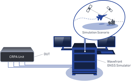
Wavefront simulator
Added to software-defined platform
Photo: Skydel Solutions
The BroadSim Wavefront Simulator is a new addition to Skydel’s software-defined platform. The BroadSim Wavefront further extends the capabilities achieved by BroadSim Anechoic, incorporating support for controlled radiation pattern antenna (CRPA) and multi-element receiver testing. Powered by Skydel SDX, the simulator’s features include phase-coherent simulation, real-time automated phase calibration, scalability from 4 to 16 elements, and advanced jamming and spoofing scenarios. Talen-X, www.talen-x.com
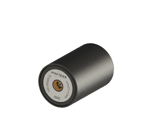
GNSS antenna
For high-precision and autonomous applications
Photo: Maxtena
The M7HCT-A-SMA is a high-accuracy, multi-frequency active quadrifilar helix GNSS antenna designed for high-precision and autonomous multi-frequency applications. The design offers concurrent GNSS reception on L1 (GPS, GLONASS, Galileo, Beidou) and L2 (GPS L2C, Galileo E5B and GLONASS L3OC) in a rugged, compact and ultra lightweight form factor. The antenna is designed for GIS, RTK and other high-accuracy GNSS applications such as the drone and automotive markets. Helicore technology provides exceptional pattern control, polarization purity and high efficiency in a 25-gram form factor. The antenna offers up to 30-dB gain for GNSS applications in one radome housing with a single SMA connector. Maxtena, maxtena.com
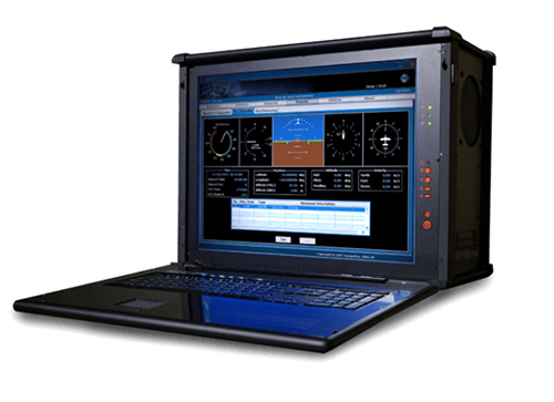
Portable simulation
Solution for field-test requirements
Photo: CAST Navigation
The CAST-1000 duplicates GPS RF signals and uses dual-frequency signal generation technology. This allows for duplicate testing in the laboratory or the field and real-time or configured control. The CAST-1000 is mobile and portable, which makes it the ideal solution for field test requirements. Producing GPS and GLONASS signals with up to 12 satellites in view, the CAST-1000 simulates signals for satellites of P code on L1 and L2 and C/A code on L1. The GPS RF signal is dual-frequency and has a 12-channel configuration for any combination of visible space vehicles. The system is highly programmable — operators can choose from an array of vehicle types and replicate dynamic motion for all kinds of vehicles, from terrestrial to aquatic, airborne to space-based. By utilizing 6-DOF dynamic profile data collected in the field and through profile configuration, a trajectory can be created. The CAST-1000 also features a performance evaluation module, allowing for comparisons between raw and filtered data. CAST Navigation, www.castnav.com
Survey & Mapping
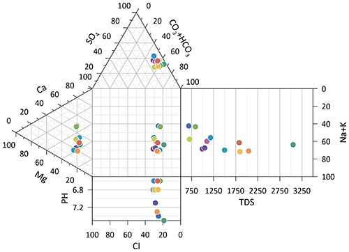
Graphing software
New plotting features
Photo: Golden Software
Version 14 of the Grapher scientific graphing package offers new plotting and customizing functionality based on user feedback. The Grapher software gives users deeper insights into their data by providing them with 80 flexible and easy-to-use 2D and 3D graphing tools for plotting, analyzing and displaying scientific data sets. The package is used extensively by scientists and engineers in oil & gas operations, hydrologic/geochemical studies, environmental consulting, mineral exploration and academic research. New or upgraded features include Enhanced Plotting (the ability to plot data in rows and columns, perform one-button Durov class plots, and easily generate multi-plot reports); and Improved Bar Charts (bar charts are more versatile, offering variable bar widths and differentiated fill colors for negative and positive). Golden Software, www.goldensoftware.com
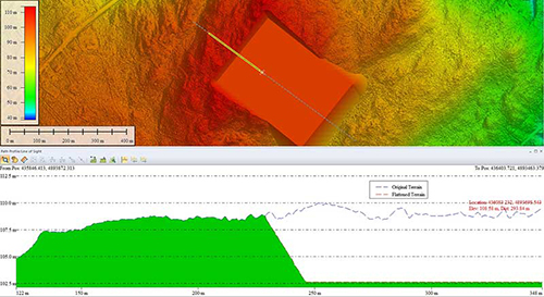
GIS software update
New lidar functionality
Photo: Blue Marble Geographics
Global Mapper version 20.1 offers new and updated geospatial tools, as well as performance improvements throughout the application. Enhancements to version 20.1 include a new zooming function in the path profile window, a digitizer tool for automatically closing gaps between features and, for lidar module users, a point proximity query function. Blue Marble Geographics, www.bluemarblegeo.com
Survey application
For the geospatial industry
Photo: Global GNSS
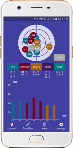
The GNSS Surveyor mobile application provides location information and quality position data in real time with sub-meter to centimeter accuracy. It connects to any external GNSS receiver via Bluetooth. Features include a one-touch configured command to communicate directly with the GNSS Bluetooth device; location information and quality of the position data in real time with centimeter accuracy; GPS data such as position, height, satellites and velocity; and constellation information for GPS, GLONASS, Galileo, BeiDou, QZSS and SBAS satellites. It also includes a direct IP feature for real-time kinematic (RTK) corrections data. An internal NTRIP client loads RTCM data from the internet. Location information is collected as latitude and longitude, altitude, speed or pace, bearing and UTC time. GNSS precision includes global coverage, centimeter-level accuracy, fast time to first fix, multi-constellation and multi-band, and highest security. Navigation uses include ground robotics navigation, lane-level navigation, heavy machine navigation, industrial navigation and tracking, and commercial UAV. Global GNSS, globalgnss.com
Indoor mapping
Slam technology removes point cloud artifacts
Photo: NavVis
The SLAM-based NavVis M6 Indoor Mobile Mapping System (IMMS) now automatically detects and removes point cloud artifacts, including moving objects in static scenes. The latest IMMS release removes artifacts from point clouds during the post-processing of scan data (see before and after image above). Fringe points and dynamic objects are two common types of point cloud artifacts that affect all 3D laser scanning devices. The NavVis M6 IMMS uses laser scanners to capture a high volume of measurement points of an environment. With the latest software update, the algorithms applied during the post-processing of scan data uses the multiple observations to detect whether measurement points actually exist in the physical space. If it is determined that the point does not exist and is instead resulting from the laser beam hitting an edge or an object moving through the space, this point is automatically removed. The result is a much cleaner, crisper point cloud that requires less clean-up time in point-cloud editing software and that is easier to use for applications such as BIM modeling. NavVis, www.navvis.com
Mobile & UAV
Adventure handhelds
Larger display, improved access to Satellite imagery
Photo: Garmin
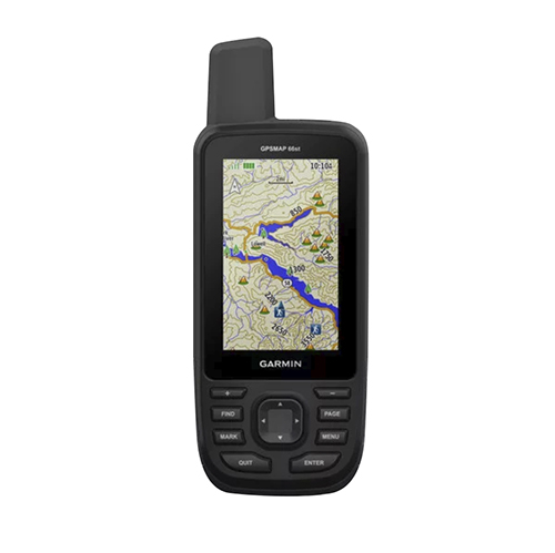
Garmin has updated two premium adventure-oriented handhelds, the GPSMAP 66s and the GPSMAP 66st, with expanded wireless connectivity, direct-to-device access to BirdsEye satellite imagery, weather forecasting and a larger 3-inch sunlight-readable color display. The GPSMAP 66st offers preloaded topographic maps for U.S. and Canada, with detail of coastlines, rivers, summits, terrain contours and geographical points. Connectivity to the new Garmin Explore app and the BirdsEye Satellite Imagery (no annual subscription) bring high-resolution photo-realistic route views. Weather updates come via Bluetooth to a compatible mobile device. The Explore app includes features for outdoor navigation, trip planning, mapping and data sharing. Features include multi-GNSS satellite support and altimeter, barometer and compass sensor capabilities; 16 hours of battery life in full GPS mode; LED flashlight and SOS beacon; built to military standards for thermal, shock and water performance (MIL-STD-810G); RINEX data logging that enables sub-meter accuracy of GPS position after post processing. Garmin, garmin.com
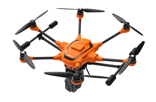
RTK Hexacopter
Integrated GNSS improves accuracy
Photo: Yuneec International
The H520 hexacopter is now available with a real-time kinematic (RTK) system. The fully integrated RTK satellite navigation enables extremely accurate recurring images and faster 3D mapping. It also makes automated inspection flights easier and more precise. The H520 RTK is suitable for commercial applications that require maximum precision. By using RTK technology, the H520 can now fly much closer to objects for inspection because the UAV positions itself precisely in the centimeter range (1 cm + ppm horizontal / 1.5 cm + ppm vertical) rather than in the meter range, which is standard for the H520. Yuneec International, us.yuneec.com
Web-based data service
Enables sharing of UAV data sets
MAGNET Collage Web is a web-based service enabling the sharing and collaboration of UAV and scanning data sets. Version 1.3 allows operators to work with more types of data with greater flexibility, including the ability to import BIM models, as well as CAD and GIS data. It can be used to overlay as-built laser scans and design data to visualize proposed changes and detect construction issues. The software supports OBJ, FBX and 3DS formats. The upgrade also includes new direct publishing functionality for CAD and GIS data files through the browser. Topcon, topconpositioning.com
The latest software release for the SLAM-based NavVis M6 Indoor Mobile Mapping System (IMMS) automatically detects and removes point cloud artifacts, including moving objects in static scenes, the company said.
This image shows what an object looks like where the laser beam has hit an edge, before and after the algorithm has been applied. (Image: NavVis)
NavVis is a global provider of indoor spatial intelligence solutions. The latest IMMS release removes artifacts from point clouds during the post-processing of scan data.
Fringe points and dynamic objects are two common types of point cloud artifacts that affect all 3D laser scanning devices. Fringe points arise when a laser beam hits the edge of an object as well as its background. This scattered beam ultimately appears as a “fringe” around the edge of the object in the point cloud.
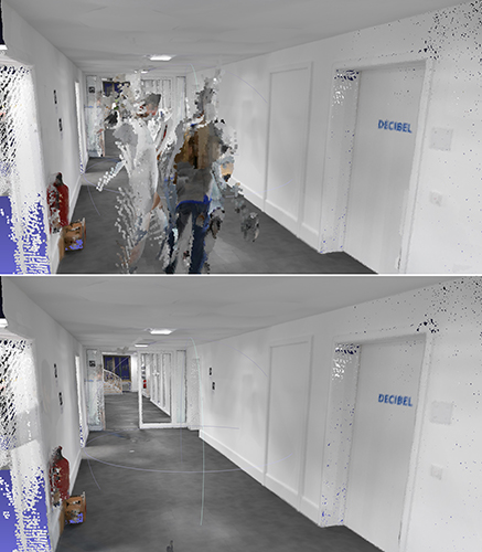
The second type of point cloud artifact results when dynamic objects, such as humans walking through a scan, are captured by the laser scanner and then appear as artifacts in the point cloud.
A point cloud before and after the algorithm has been applied to a dynamic object. (Image: NavVis)
According to the company, the NavVis M6 IMMS is a simultaneous localization and mapping (SLAM)-based system that uses laser scanners to capture a high volume of measurement points of an environment. As SLAM-based mobile mapping systems move through the environment while scanning it, objects are observed from multiple different angles and positions.
With the latest software update, the algorithms applied during the post-processing of scan data use those multiple observations to detect whether measurement points actually exist in the physical space. If it is determined that the point does not exist and is instead resulting from the laser beam hitting an edge or an object moving through the space, this point is automatically removed.
The result is a much cleaner, crisper point cloud that requires less clean up time in point cloud editing software and that is easier to use for applications such as BIM modeling, the company said.
“We have been working hard to develop a very precise SLAM technology that significantly improves the quality of point clouds captured by a mobile device,” said Georg Schroth, NavVis co-founder and CTO. “As this latest software feature shows, SLAM offers a lot of potential for laser scanning and AEC professionals who are looking for technology that not only speeds up the capture of data but also delivers high quality point clouds. We see a lot of potential in this technology and look forward to sharing future innovations.”
NavVis, a provider of indoor spatial intelligence technology, can now automatically convert E57 point cloud files into interactive, realistic 360-degree walkthroughs, following the latest software upgrade to IndoorViewer.
Visitors to Intergeo 2018 can demo the new NavVis IndoorViewer release as well as the NavVis M6 indoor mobile mapping system by visiting NavVis in Hall 12.1 at booth 12.1D.086.
Image: NavVis
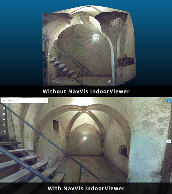
NavVis IndoorViewer is a web-based application that displays realistic digital twins using 360-degree panoramic images, point clouds and maps generated by 3D scanning devices. Users can move around digital twins of scanned spaces as if they are on site and use the interactive functionality to add, search for and route to geotagged information and take accurate measurements.
The intuitive user interface and functionality has made NavVis IndoorViewer a valuable deliverable for laser scanning professionals who want to extend the use of point clouds beyond BIM models and building plans to a wider range of building stakeholders who would also benefit from 3D scan data.
This is particularly relevant for stakeholders working on complex projects or properties, such as manufacturing facilities and construction sites, where IndoorViewer enables remote access to the site and is used as a platform for collaboration and exchanging information, the company said.
“IndoorViewer was originally developed to display the data captured by our indoor mobile mapping system in a way that is accessible to every user,” said Felix Reinshagen, NavVis CEO. “In recent years, we have seen that making scan data available to every building stakeholder is fulfilling an unmet need. Many of our partners using a NavVis indoor mobile mapping system for conventional scanning projects are offering IndoorViewer as an additional deliverable to increase the number of stakeholders who can make use of this data.”
“To meet the growing demand for extending the use of valuable 3D scan data, we developed a feature that automatically renders 360-degree immersive images from structured E57 point cloud files. The latest software release brings the full functionality of IndoorViewer to E57 point cloud files and therefore marks an important step towards our goal of making scan data meaningful for every building stakeholder.”
NavVis IndoorViewer currently supports third party point cloud files in most standard formats. However, a key component of the immersive experience that NavVis IndoorViewer provides is the 360-degree panoramic images.
The new IndoorViewer feature bridges this gap for structured E57 files by automatically rendering 360-degree immersive imagery from E57 point cloud files. This means data collected by terrestrial laser scanners can now also be used to create realistic, immersive 360-degree walkthroughs that can be published and shared online without the need to download or install software.
The E57 panorama extractor is available as part of a free software upgrade to IndoorViewer subscribers.
Mapping company NavVis has launched the M6, a next-generation indoor mobile-mapping system that the company says can overcome the scalability and data quality constraints of reality capture technology.
Surveyors and architecture, engineering and construction (AEC) professionals can now use reality-capture technology for large-scale indoor mapping projects. The M6 can be used for factory planning and creating and updating as-built BIM (building information modeling) models and construction monitoring.
The NavVis M6 is an all-in-one system that captures 360-degree immersive imagery, photorealistic point clouds, Bluetooth beacons, Wi-Fi signals and magnetic field data.
The NavVis M6 features a mobile lidar system that lets it scan up to 30 times faster than stationary devices, letting users capture up to 30,000 square meters in a day.
Cutting-edge 6D simultaneous localization and mapping (SLAM) technology significantly improves the quality of data captured. Thanks to 6D SLAM, M6 continuously scans even complex indoor environments, including uneven surfaces or changing elevations such as ramps, open spaces or long corridors without compromising the quality of the data.
M6’s innovative software is complemented by hardware features designed to improve the quality of data and ease of capture: four laser scanners with a range of up to 100 meters are arranged to maximize scan coverage, while six cameras automatically take high-resolution images during mapping. The innovative design of the M6 includes camera placement that keeps the operator in a blind spot.
NavVis IndoorViewer software gives stakeholders access to the scanned environment through an interactive virtual building in their browser.
“The NavVis M6 marks a quantum leap in indoor mobile mapping,” Felix Reinshagen, CEO of NavVis. “Anyone who needs to scan large properties, run repeated scans or would like to move into the field of reality capture will profit from the groundbreaking data quality.
“With M6, users can now quickly capture large, complex indoor environments for typical tasks such as updating floorplans, documenting construction progress or creating as-built BIM models. At the same time, M6 captures the data needed to provide customers with additional deliverables such as browser-based immersive walkthroughs and indoor navigation,” Reinshagen said.
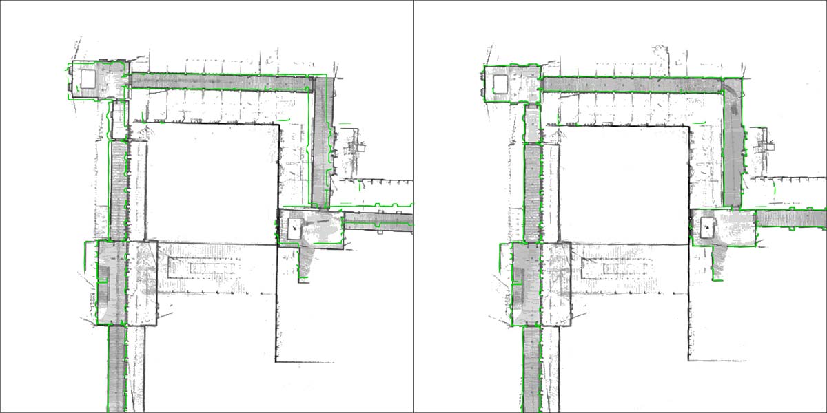
NavVis, a mobile indoor mapping, visualization and navigation company, released new mapping software that significantly improves the accuracy of simultaneous localization and mapping (SLAM) technology in indoor environments, such as long corridors, the company said.
The software update will be available for users of the NavVis M3 Trolley and will significantly improve the accuracy of the resulting maps and point clouds. NavVis’ mobile mapping system, the M3 Trolley, builds upon SLAM to increase speed and efficiency when scanning buildings.
The images below demonstrate the impact of NavVis Precision SLAM technology. The left image depicts a long corridor mapped with a conventional SLAM system where the above-mentioned drift error has occurred. The green outline shows how the map deviates from the true structure. The image on the right shows the significantly improved map accuracy obtained when mapping the same area using the M3 Trolley with the new Precision SLAM technology.
Image: NavVis
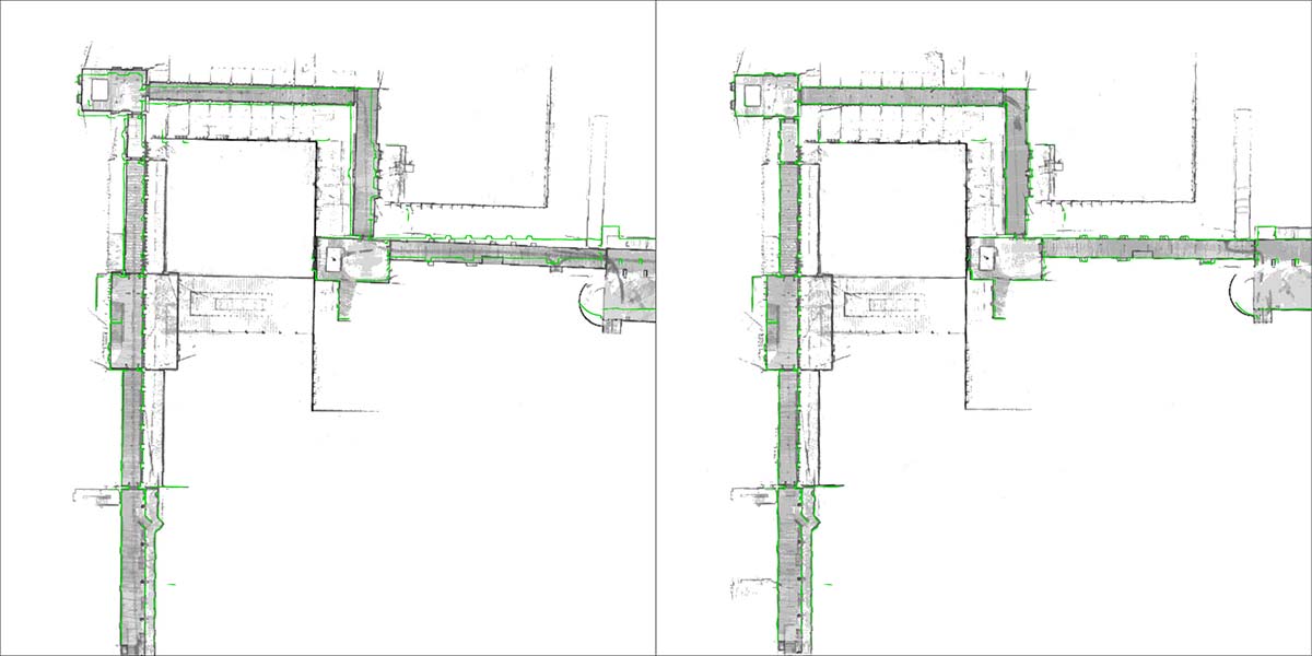
Here is a closer look:
Image: NavVis
SLAM is a technique originally developed by the robotics industry that is now increasingly being used in surveying and autonomous driving technologies. It solves a core problem that long plagued robotics engineers by enabling a device to determine its location while simultaneously mapping an unknown environment. This is done by chaining millions of measurements into a trajectory estimate.
However, even when a device captures highly accurate individual measurements, chaining them will result in an accumulation of noise and tiny measurement uncertainties. Over time, the estimated motion will start to deviate from the true motion (drift error). This can often be observed as a slight bending of long corridors that are actually straight. All available SLAM systems — regardless of whether these use LIDARs or other sensors — are inherently affected by this phenomenon.
The NavVis Precision SLAM technology significantly reduces drift error and improves the SLAM accuracy. This is particularly evident in cases where complementary techniques such as loop closures cannot be deployed, if, for example, the building’s layout does not allow for it.
Precision SLAM even improves accuracy when SLAM anchors are used to incorporate ground control points into the mapping process.
“I am very excited about our new Precision SLAM technology,” said Stefan Romberg, head of mapping and perception at NavVis. “We are always striving for the highest possible map and point-cloud accuracy and improving SLAM is a critical component to being successful. It is widely known among SLAM developers and users that complementary approaches such as loop closures or ground control points are needed to achieve a high accuracy.
“However, with the Precision SLAM technology we have developed an approach that not only nicely complements the former techniques but is especially evident when these have little effect or cannot be used.”