Tag: Philip Mattos

  • Quad-Constellation Receiver: GPS, GLONASS, Galileo, BeiDou

    The implementation changes and first live tests of BeiDou and Galileo on Teseo-3 GNSS chips developed in 2013 are covered, bringing it to a four-constellation machine. By 2020, we expect to have four global constellations all on the same band, giving us more than 100 satellites — under clear sky, as many as 30 or 40 simultaneously.

    By Philip G. Mattos and Fabio Pisoni

    Multi-constellation GNSS first became widely available in 2010/2011, but only as two constellations, GPS+GLONASS. Although receivers at that time may have supported Galileo, there were no usable satellites. BeiDou was a name only, as without a spec (an interface control document, or ICD), no receivers could be built. However, the hardware development time of receivers had been effectively shortened: the Galileo ICD had been available for years, BeiDou codes had been reverse-engineered by Grace Gao and colleagues at Stanford, and at the end of 2011 they were confirmed by the so-called test ICD, which allowed signal testing without yet releasing message characteristics or content.

    The last weeks of 2012 saw two great leaps forward for GNSS. Galileo IOV3 and 4 started transmitting at the beginning of December, bringing the constellation to four and making positioning possible for about two hours a day. At the end of December, the Chinese issued the BeiDou ICD, allowing the final steps of message decode and ephemeris calculation to be added to systems that had been tracking BeiDou for many months, and thus supporting positioning. The Teseo-2 receiver from STMicroelectronics has been available for some years, so apart from software development, it was just waiting for Galileo satellites; however, for BeiDou it needed hardware support in the form of an additional RF front end. Additionally, while it could support all four constellations, it could not support BeiDou and GPS/Galileo at the same time, as without the BeiDou ICD the spreading codes had to be software-generated and used from a memory-based code generator, thus blocking the GPS/Galileo part of the machine.

    The Teseo-3 receiver appeared late in 2013, returning to the optimum single-chip form factor: RF integrated with digital silicon and flash memory in the same package, enabling simultaneous use of BeiDou and GPS/Galileo signals. Multi-constellation in 2012 was GPS+GLONASS, which brought huge benefits in urban canyons with up to 20 visible satellites in an open sky. Now, for two hours a day in Europe while the Galileo IOVs are visible, we can run three constellations, and in the China region, GPS/BeiDou/Galileo is the preferred choice.

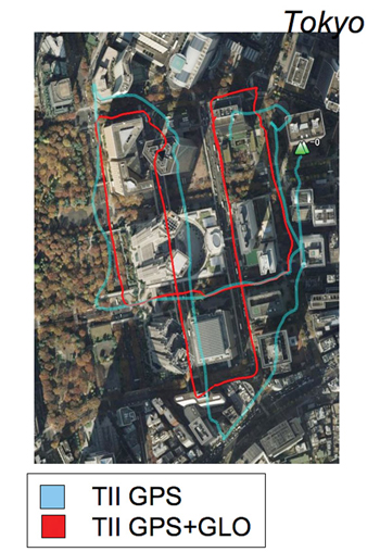
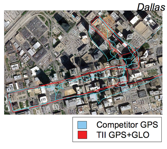
    This article covers the first tracking of four Galileo satellites on December 4, 2012, first positioning with Galileo, and first positioning with BeiDou in January 2013. It will cover static and road tests of each constellation individually and together as a single positioning solution. Road tests in the United States/Europe will combine GPS/GLONASS/Galileo, while tests in the China region will combine GPS/Galileo/BeiDou. Results will be discussed from a technical point of view, while the market future of multi-constellation hardware will also be considered.

    In the 2010–2020 timeframe, GLONASS and BeiDou (1602 MHz FDMA and 1561 MHz respectively) cost extra silicon in both RF and digital hardware, and cause marginal extra jamming vulnerability due to the 50 MHz bandwidth of the front end. The extra silicon also causes extra power consumption.

    After 2020, GLONASS is expected to have the L1OC signal operational, CDMA on the GPS/Galileo frequency, and BeiDou is expected both to have expanded worldwide, and also to have the B3 signal fully operational, again on 1575 MHz. At that point we will have four global constellations all on the same band, giving us more than 100 satellites. With a clear sky, the user might expect to see more than 30, sometimes 40, satellites simultaneously.

    Besides the performance benefits in terms of urban canyon availability and accuracy, this allows the receiver to be greatly simplified. While code generators will require great flexibility to generate any of the code families at will, the actual signal path will be greatly simplified: just one path in both RF (analog) and baseband (digital) processing, including all the notch filters, derotation, and so on. And this will greatly reduce the power consumption.

    Will the market want to take the benefit in power consumption and silicon area, or will it prefer to reuse those resources by becoming dual-frequency, adding also the lower-L-band signals, initially L5/E5, but possibly also L2/L3/L6 ? The current view is that the consumer receiver will go no further than L5/E5, but that the hooks will be built-in to allow the same silicon to be used in professional receivers also, or in L2C implementations to take advantage of the earlier availability of a full constellation of GPS-L2C rather than GPS-L5.

    This article presents both technical results of field trials of the quad-constellation receiver, and also the forward looking view of how receivers will grow through multi-frequency and shrink through the growing signal commonalities over this decade.

    History

    Galileo was put into the ST GPS/GNSS receiver hardware from 2006 to 2008, with a new RF and an FPGA-based baseband under the EU-funded GR-PosTer project. While a production baseband (Cartesio-plus) followed in high volume from 2009, in real life it was still plain GPS due to the absence of Galileo satellites.

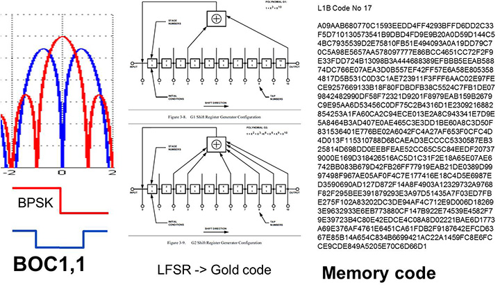
    The changed characteristics in Galileo that drove hardware upgrades are shown in Figure 1. The binary offset carrier BOC(1,1) modulation stretches the bandwidth, affecting the RF, while both the BOC and the memory codes affect the baseband silicon in the code-generator area.

    Figure 1. Changes for Galileo.
    Figure 1. Changes for Galileo.

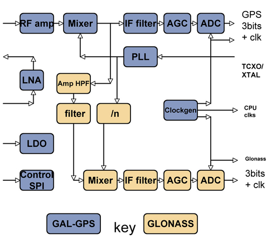
    Next was the return to strength of the GLONASS constellation, meaning receivers were actually needed before Galileo. However the different center frequency (1602 MHz), and the multi-channel nature of the FDMA meant more major changes to the hardware. As shown in Figure 2 in orange, a second mixer was added, with second IF path and A/D converter.

    Figure 2. Teseo-2 RF hardware changes for GLONASS.
    Figure 2. Teseo-2 RF hardware changes for GLONASS.
    Figure 3. Teseo-2 and Teseo-3 baseband changes for GLONASS.
    Figure 3. Teseo-2 and Teseo-3 baseband changes for GLONASS.

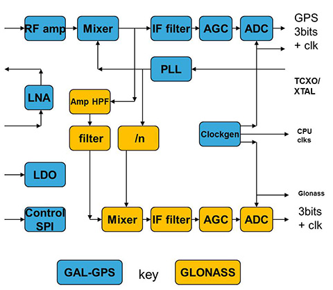
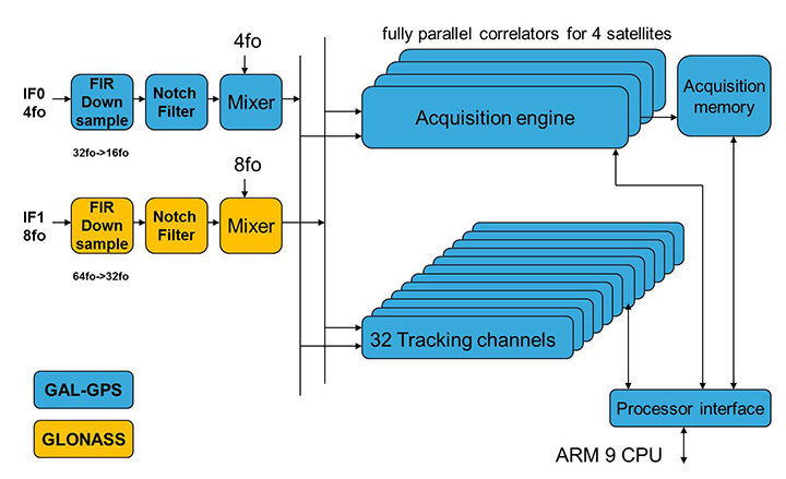
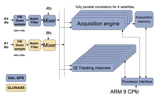
    The baseband changes added a second pre-processing chain and configured all the acquisition channels and tracking channels to flexibly select either input chain. Less visible, the code-generators were modified to support 511 chip codes and 511kchips/sec rates.

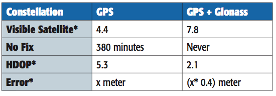
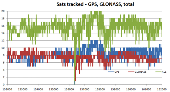
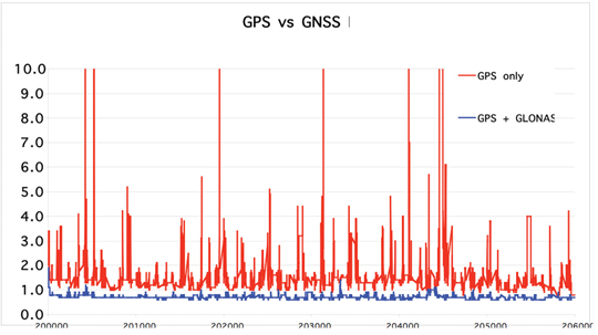
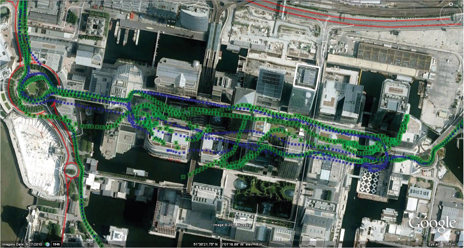
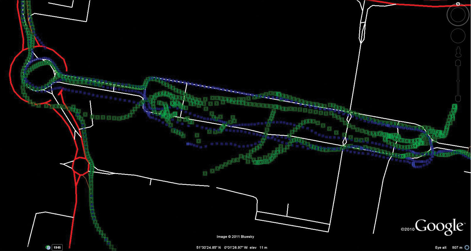
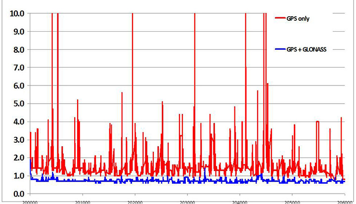
    Teseo-2 appeared with GPS/GLONASS support in 2010, and demonstrated the benefit of GNSS in urban canyons, as shown by the dilution of precision (DOP) plot for central London in Figure 4. The GPS-only receiver (in red) has frequent DOP excursions beyond limits, resulting either in bad accuracy or even interrupted fix availability. In contrast, the GNSS version (in blue) has a DOP generally below 1, with a single maximum of 1.4, and thus 100 percent availability. Tracking 16 satellites, even if many are via non-line-of-sight (NLOS) reflected paths, allows sophisticated elimination of distorted measurements but still continuous, and hence accurate, positioning.

    Figure 4. DOP/accuracy benefits of GNSS.
    Figure 4. DOP/accuracy benefits of GNSS.

    BeiDou

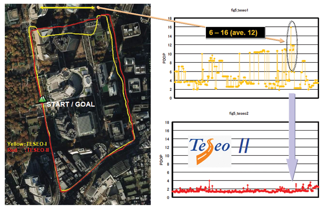
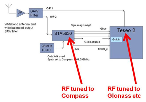
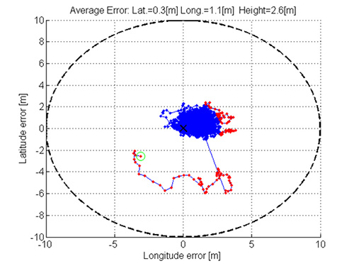
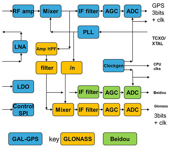
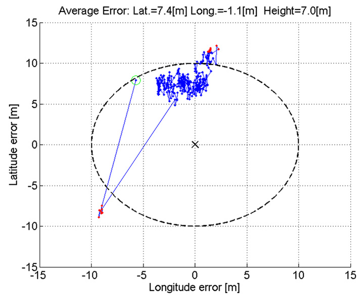
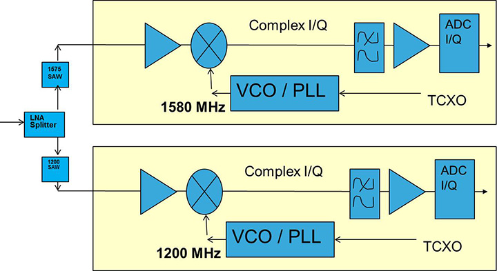
    Like Galileo, BeiDou is a story of chapters. Chapter 1 was no ICD, and running on a demo dual-RF architecture as per the schematic shown in Figure 5. Chapter 2 was the same hardware with the test ICD, so all satellites, but still no positioning. Chapter 3 was the full ICD giving positioning in January 2013 (Figure 6), then running on the real Teseo-3 silicon in September 2013, shown in Figure 7.

    Figure 5. Demo Teseo-2 dual RF implementation of BeiDou.
    Figure 5. Demo Teseo-2 dual RF implementation of BeiDou.
    Figure 6. Beidou positioning results.
    Figure 6. Beidou positioning results.
    Figure 7. Teseo 3 development board.
    Figure 7. Teseo 3 development board.

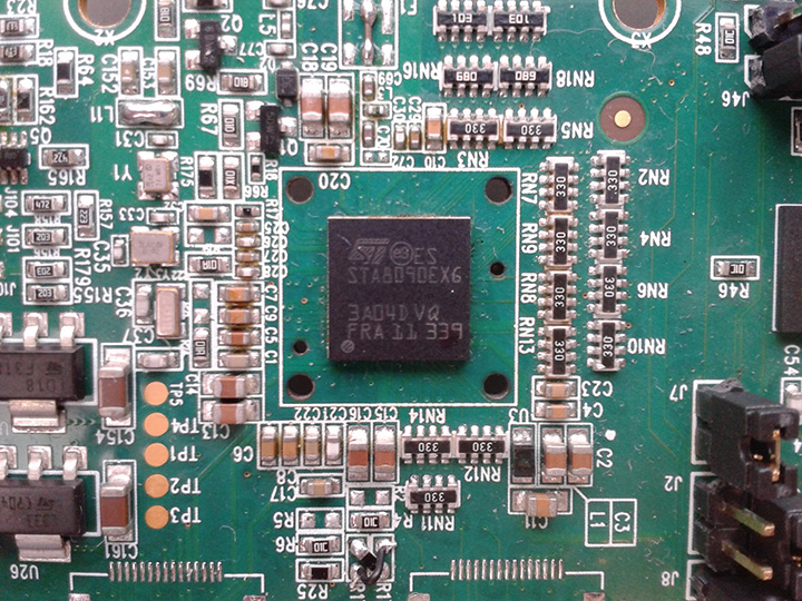
    The Teseo-3 has an on-chip RF section capable of GPS, Galileo, GLONASS and BeiDou, so no external RF is needed.

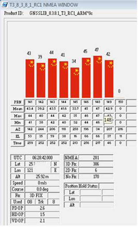
    The clear green space around the Teseo-3 chip in the photo and the four mounting holes are for the bolt-down socket used to hold chips during testing, while the chip shown is soldered directly to the board. Figure 8A shows the development board tracking eight BeiDou satellites visible from Taiwan.

    However, the silicon is not designed to be single-constellation; it is designed to use all the satellites in the sky. Figure 8b shows another test using GPS and BeiDou satellites simultaneously.

    Figure 8A. Beidou.
    Figure 8A. Beidou.
    Figure 8b. GPS+Beidou.
    Figure 8b. GPS+Beidou.

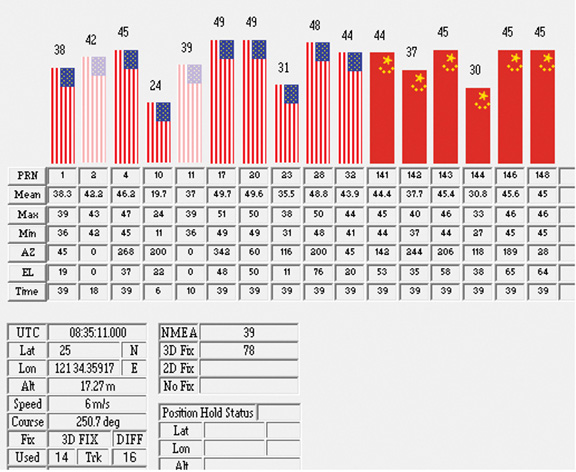
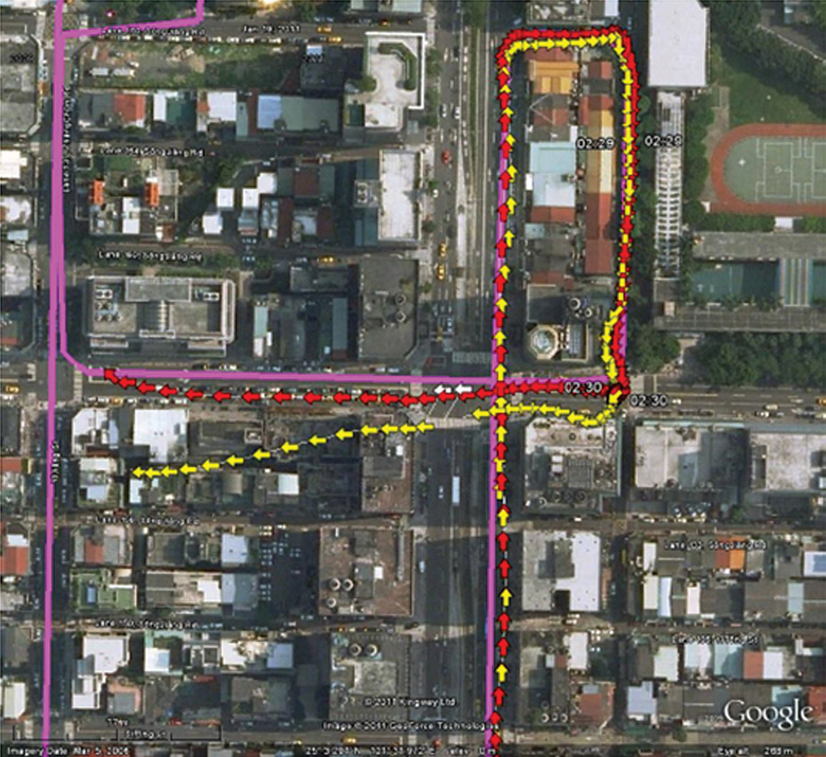
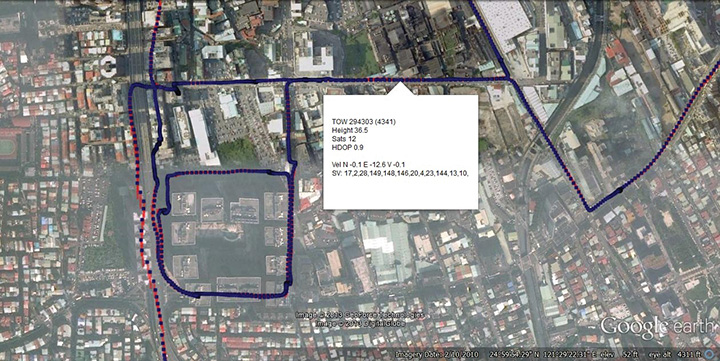
    A mobile demo on the Teseo-3 model is shown running GPS plus BeiDou in Figure 9, a road test in Taipei. Satellites (SV) up to 32 are GPS, those over 140 are BeiDou, in the status window shown: total 13 satellites in a high-rise city area, though many are non-LOS.

    Figure 9. GPS + Beidou roadtrack in Taipei.
    Figure 9. GPS + Beidou roadtrack in Taipei.

    Extending the hardware to add BeiDou, which is on 1561 MHz and thus a third center frequency, meant adding another path through the IF stages of the on-chip radio. After the first mixer, GPS is at 4 MHz, and GLONASS at about 30 MHz, but BeiDou is at minus 10 MHz. While the IF strip in general is real, rather than complex (IQ), the output of the mixer and input to the first filter stage is complex, and thus can discriminate between positive frequencies (from the upper sideband) and negative ones (from the lower sideband), and this is normally used to give good image rejection. In the case of BeiDou, the filter input is modified to take the lower sideband, that is, negative frequencies, and a second mixer is not required; the IF filter is tuned to 10 MHz. The new blocks for BeiDou are shown in green in Figure 10. The baseband has no new blocks, but the code generator has been modified to generate the BeiDou codes (and, in fact, made flexible to generate many other code types and lengths). Two forms of Teseo-3 baseband are envisaged, the first being for low-cost, low-current continues to have two input paths, so must choose between GLONASS and BeiDou as required. A future high-end model may have an extra input processing path to allow use of BeiDou and GLONASS simultaneously.

    Figure 10. Teseo-3 RF changes for Beidou shown in green.
    Figure 10. Teseo-3 RF changes for Beidou shown in green.

    Galileo Again

    Maintaining the chronological sequence, Galileo gets a second chapter in three steps. In December 2012, it was possible for the first time to track four IOV satellites simultaneously, though not to position due to the absence of valid orbit data. In March 2012, it was possible for the first time to demonstrate live positioning, and this was done using Teseo-2 simultaneously by ESA at ESTEC and STMicro in Naples and Milan, our software development centres.

    The demos were repeated in public for the press on July 24, 2013, at Fucino, Italy’s satellite earth station, with ESA/EC using the test user receiver (TUR) from Septentrio, and ST running simultaneous tests at its Italian labs. Figure 11 and Figure 12 show the position results for the data and pilot channels respectively, with independent LMS fixes. In real life, the fixes would be from a Kalman filter, and would be from a combined E1-B/E1-C channel, to take advantage of the better tracking on the pilot.

    Figure 11. Galileo positioning, E1-B.
    Figure 11. Galileo positioning, E1-B.
    Figure 12. Galileo positioning, E1-C.
    Figure 12. Galileo positioning, E1-C.

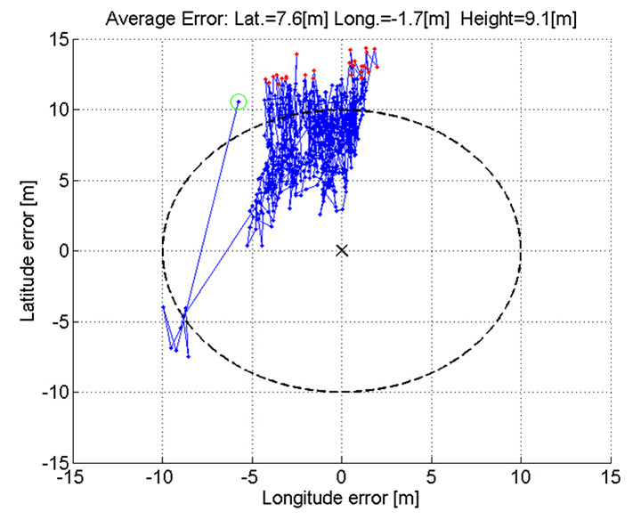
    Good accuracy is not expected from Galileo at this stage. The four satellites, while orbited to give good common visibility, do not also give a good DOP; the full set of ground monitoring stations is not yet implemented and cannot be well calibrated with such a small constellation. Finally, the ionospheric correction data is not yet available. Despite these problems, the residuals on the solutions, against a known fixed position for the rooftop antenna, are very respectable, shown in Figure 13.

    Figure 13. Galileo residuals, L1-B.
    Figure 13. Galileo residuals, L1-B.

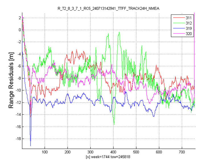
    The common mode value is unimportant, representing only an offset in the receiver clock, and 10 meters is about 30 nanoseconds. The accuracy indicator is the spread between satellites, which is very respectable for a code-only receiver without full iono correction, especially around 640 on the TOW scale, where it is less than 2 meters. The rapid and major variation on the green data around t=400 is considered to be multipath, as the roof antenna is not ideally positioned with respect to other machinery and equipment also installed on the roof.

    QZSS and GPS-III/L1C

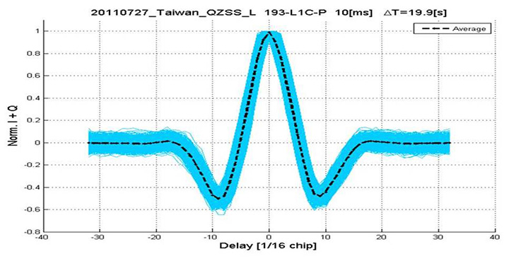
    Teseo-2 has supported the legacy (C/A code) signal on QZSS for some time, but Teseo-3 has been upgraded to handle the GPS-III/L1-C signal, waiting for modernized GPS. This signal is already available on the QZSS satellite, allowing tests with real signals. Significant changes were required in the baseband hardware, as the spreading code is a Weill code, whose generation complexity is such that it is generated once when the satellite is selected, then replayed real time from memory. Additionally it is long, in two domains. It is 10230 chips — that is, long to store but also long in time, with a 10-millisecond epoch. On Teseo-3, the legacy C/A code is used to determine code-phase and frequency before handing over to the Weill code for tracking.

    Using a long-range crystal ball and looking far into the future, a model of the future Teseo-4 DSP hardware is available, with 64 correlation taps per satellite. Running this on the captured QZSS L1-C signal gives the correlation response shown in Figure 14. Having multiple taps removes all ambiguity from the BOC signal, simultaneously removing data transitions, which can alternatively be pre-stripped using the known pilot secondary code (which on GPS III is 5 dB stronger than the data signal). The resultant plot represents 2,000 epochs, each of 10 milliseconds, plotted in blue, with integrated result for the full 20 seconds shown in the black dashed line. Assuming vehicle dynamics is taken out using carrier Doppler, this allows extremely precise measurement of the code phase, or analysis of any multipath in order to remove it. This RF data was captured on a benign site with a static antenna, so it shows little distortion.

    Figure 14. L1-C tracking on QZSS satellite.
    Figure 14. L1-C tracking on QZSS satellite.
    Figure 15. Dual RF implementation of dual-band front end.
    Figure 15. Dual RF implementation of dual-band front end.

    The Future

    Having already built in extreme flexibility to the code generators to support all known signals and generalized likely future ones, the main step for the future is to support multiple frequencies, starting with adding L5 and/or L2, but as before, ensuring that enough flexibility is built in to allow any rational user/customer choice. It is not viable for us to make silicon for low-volume combinations, nor to divide the overall market over different chips. Thus our mainstream chip must also support the lower volume options.

    We cannot, however, impose silicon area or power consumption penalties on the high-volume customer, or he will not buy our product.

    Thus, our solution to multi-frequency is to make an RF that can support either band switchably, with the high band integrated on the volume single-chip GNSS. Customers who also need the low band can then add a second RF of identical design externally, connected to the expansion port on the baseband, which has always existed for diagnostic purposes, and was how BeiDou was demonstrated on T2. By being an RF of identical design to the internal one, it incurs no extra design effort, and would probably be produced anyway as a test chip during the development of the integrated single-chip version. Without this approach, the low volume of sales of a dual-band radio, or a low-band radio, would never repay its development costs.

    Conclusions

    All four constellations have been demonstrated with live satellite signals on Teseo-2, a high-volume production chip for several years, and on Teseo-3 including use in combinations as a single multi-constellation positioning solution. With the advent of Teseo-3, with optimized BeiDou processing and hardware support for GPS-3/L1C, a long-term single-chip solution is offered.

    For the future, dual-frequency solutions are in the pipeline, allowing full advantage of carrier phase, and research into moving precise point positioning and real-time kinematic into the automotive market for fields such as advanced driver-assistance systems.

    Acknowledgments

    Teseo III design and development is supported by the  European Commission HIMALAYA FP-7 project.

    This article is based on a technical paper first presented at ION-GNSS+ 2013 in Nashville, Tennessee.

    ST GPS products, chipsets and software, baseband and RF are developed by a distributed team in: Bristol, UK (system R&D, software R&D; Milan, Italy (Silicon implementation, algorithm modelling and verification); Naples, Italy (software implementation and validation); Catania, Sicily, Italy (Galileo software, RF design and production); Noida, India (verification and FPGA). The contribution of all these teams is gratefully acknowledged.


    Philip G. Mattos received an external Ph.D. on his GPS work from Bristol University. Since 1989 he has worked exclusively on GNSS implementations, RF, baseband and applications. He is consulting on the next-generation GNSS chips, including one-chip GPS (RF+digital), and high-sensitivity GPS and Galileo for indoor applications, and combined GPS/Galileo/GLONASS chipsets. In 2008-2009, he re-implemented LORAN on the GPS CPU, and in 2009-2010 led the GLONASS implementation team. He is leading the team on L1C and BeiDou implementation, and the creation of totally generic hardware that can handle even future unknown systems.

    Fabio Pisoni has been with the GNSS System Team at STMicroelectronics since 2009. He received a master’s degree in electronics from Politecnico di Milano, Italy, in 1994. He was previously with the GNSS DSP and System Team in Nemerix SA and has earlier working experience in communications (multi-carrier receivers).

  • Consumer GPS/GLONASS: Accuracy and Availability Trials of a One-Chip Receiver in Obstructed Environments

    By Philip Mattos, STMicroelectronics R&D Ltd.

    A one-chip multiconstellation GNSS receiver, now in volume production, has been tested in severe urban environments to demonstrate the benefits of multiconstellation operation in a consumer receiver. Bringing combined GPS/GLONASS from a few tens of thousands of surveying receivers to many millions of consumer units, starting with satnav personal navigation devices in 2011, followed by OEM car systems and mobile phones, significant shifts the marketplace. The confidence of millions of units in use and on offer should encourage manufacturers of frequency-specific components, such as antennas and SAW filters, to enter volume mode in terms of size and price.

    One-chip GPS/GLONASS receiver trials in London, Tokyo, and Texas sought to demonstrate that the inclusion of all visible GLONASS satellites in the position solution, in addition to those from GPS, produces much greater availability in urban canyons, and in areas of marginal availability, much greater accuracy.

    Multi-constellation receivers are needed at the consumer level to make more satellites available in urban canyon environments, where only a partial view of the sky is available and where extreme integrity is required to reject unusable signals, while continuing to operate on other signals deeply degraded by multiple reflection and attenuation. This article briefly outlines the difficulties of integrating a currently non-compatible system (GLONASS), offering an economic solution in the mass market where cost is king, but performance demands in terms of low signal, power consumption, time-to-first-fix, and availability are extreme. While the accuracy achieved is not at survey levels, we deem it sufficient to meet consumer demands even at the worst signal conditions.

    The aim is to provide improved indoor and urban canyon availability for mass-market GNSS by using all available satellites; in 2011, that requires GLONASS support, as the constellation availability precedes Galileo by around three years. The aim is to overcome the hardware incompatibility issues of GLONASS, that is, its frequency division multiple access (FDMA) signal rather than the code division multiple access format used by GPS, different centre frequency, and different chipping rate, all without adding significantly to the silicon cost of the receiver chipset. This then allows a total satellite constellation of about 50 to be used at present, even before two recently launched Galileo IOV satellites.

    It is expected that in benign conditions the additional satellites will give little benefit, as availability approaches 100 percent, and accuracy is excellent, with GPS alone. Though dominated by the ionosphere, using seven, eight, or nine satellites in the fix minimises the amount of error that feeds through to the final position.

    In marginal conditions, where GPS can give a position, but is using 3/4/5 satellites and those are clustered in the narrow visible part of the sky resulting in poor DOP values, the increased number of satellites benefits the accuracy greatly, due to both improved DOP and multipath-error averaging. Limited satellites mean the full multipath errors map into position and are magnified by the DOP. Adding the second constellation means more clear-view satellites for accuracy, more total satellites to minimise the errors, and the errors are less magnified by the geometry due to better DOP.

    In extreme conditions, where insufficient GPS satellites are seen to give a fix, the additional GLONASS satellites increase the availability to 100 percent (excluding actual tunnels).

    Availability is a self-enhancing positive feedback loop… if satellites are always tracked, even if rejected on a quality basis by the RAIM/fault detection and exclusion (FDE) algorithms, then they do not need to be reacquired, so become available for use earlier. If position can be maintained, then the code phases for obstructed satellites can continue to be predicted accurately, allowing instant reacquisition after obstruction, and instant use as no code pull-in time is required. Once availability is lost, the reverse applies, as wrong position means worse prediction, longer re-acquisition, and hence again less availability.

    The extra visible satellites are very significant for the consumer, particularly — as for example with self-assistance where the minimum constellation is five satellites, not three to four — to autonomously establish that all satellites are healthy using receiver-autonomous integrity monitoring (RAIM) methods. Self-assistance has further major benefits for GLONASS, in that no infrastructure is required, so there will be no delay waiting for GLONASS assistance servers to roll out. The GLONASS method of transmitting satellite orbits is also very suitable for the self-assistance algorithm, saving translation into and out of the Kepler format.

    Significance of Work

    Previous attempts to characterize the multi-constellation benefits in urban environments have been handicapped by the need to use professional receivers not designed for such signal conditions, and by the need to generate a separate result for each constellation or sacrifice one satellite measurement for clock control. These problems made them unrepresentative of the performance to be expected from the volume consumer device.

    This new implementation is significant in being a true consumer receiver for high sensitivity, fully integrated both for measurement and for computation. Thus fully realistic trials are reported for the first time.

    Background

    The tests were performed on the Teseo-II single chip GNSS receiver (STA-8088). A brief history: our 2009 product Cartesio+ already included GPS/Galileo, and the digital signal processor (DSP) design has been extended to include GLONASS also for Teseo2, the 2010 product. Test results with real signal data through FPGA implementations of the baseband started in late 2009, and with the full product chip in 2010.

    The architectural design showed that the silicon could be implemented with only small additional silicon area. Changes to the baseband DSP hardware and software were small and were included in the next scheduled upgrade of the chip, Teseo2. The RF chip silicon requires much greater attention, duplicating the intermediate frequency (IF) path and analog-digtal converter (ADC), with additional frequency conversion and a much wider IF filter bandwidth; however, as the RF silicon area is very small in total, even a 30 percent increase here is not a significant percentage increase on the whole chip. As the design is for an integrated single chip system (RF and baseband, from antenna to position, velocity, and timing (PVT) solution), the overall silicon area on a 65-nanometer process is very small.

    Commercially, it is new to include all three constellations in a single consumer chip. Technically it is new to use a pool of constellation-independent channels for GLONASS, though standard for GPS/Galileo. Achieving this flexibility has also required new techniques to manage differing RF hardware delays, different chipping rates, in addition to the coordinated universal time (UTC) offset and geoid offset problems already well known to the surveying community.

    It is also very unusual to go direct to a single-chip solution (RF+baseband+CPU) for such a major technology step. The confidence for this step comes from the provenance of the RF and the baseband, the RF being an extension of the STA5630 RF used with Cartesio+, and the baseband being significant but not major modifications of the GPS/Galileo DSP used inside Cartesio+. 5630/Cartesio+ were proven in volume production as separate chips before the single-chip three-constellation chip starts production.

    The steps forward from the previous generation of hardware are on chip RF, Galileo support, GLONASS support. While Galileo can pass down the existing GPS chain, with appropriate bandwidth changes, additional changes are required for GLONASS: see Figures 1 and 2.

    figure1 Philip Mattos, STMicroelectronics R&D Ltd.
    Figure 1. RF changes to support GLONASS.
    figure2 Source: Philip Mattos, STMicroelectronics R&D Ltd.
    Figure 2. Baseband changes to support GLONASS.


    In the RF section, the LNA, RF amp, and first mixer are shared by both paths, in order to save external costs and pins for the equipment manufacturer, and also to minimize power consumption. Then the GLONASS signal, now at around 30 MHz, is tapped off into a secondary path shown in brown, mixed down to 8 MHz and fed to a separate ADC and thus to the baseband.

    In the baseband, an additional pre-conditioning path is provided, again shown in brown, which converts the 8 MHz signal down to baseband, provides anti-jammer notch filters, and reduces the sample rate to the standard 16fo expected by the DSP hardware.

    The existing acquisition engines and tracking channels can then select whether to take the GPS/Galileo signal, or the GLONASS signal, making the allocation of channels to constellations completely flexible.

    Less visible but very important to the system performance is the software controlling these hardware resources, first to close tracking loops and take measurements, and secondly the Kalman filter that converts the measurements to the PVT data required by the user. This was all structurally modified to support multiple constellations, rather than simply adding GLONASS, in order that future extensions of the software to other future systems becomes an evolutionary task rather than a major re-write.

    The software ran on real silicon in 2010, but using signals from either simulator or static roof antennas, where accuracy and availability of GPS alone are so good that there is little room for improvement. In early 2011, prototype satnav hardware using production chips, antennas, and cases became available, making mobile field trials viable.

    Actual Results

    Results have already been seen from trials using professional receivers with independent GPS and GLONASS measurements. However, those tests were not representative of the consumer receiver because they are not high sensitivity; because the receivers require enough clean signal to operate a PLL, which is not realistic in a mobile city environment; and because they were creating two separate solutions, thus needing a continuous extra satellite to resolve inter-system time differences.

    A 2010 simulation of visible satellites in a typical urban canyon of downtown Milan, Italy, produced the results, every minute averaged for a full 24 hours, shown in Table 1. The average number of satellites visible rises from 4.4 with GPS alone, to 7.8 for GPS+GLONASS, with the result that there are then zero no-fix samples. With GPS alone there were 380 no-fix samples, or 26 percent of the time.

     Table 1. Accuracy and availability of GPS and GPS+GLONASS, averaged over 24 hours. Source: Philip Mattos, STMicroelectronics R&D Ltd.
    Table 1. Accuracy and availability of GPS and GPS+GLONASS, averaged over 24 hours.

    However, availability is not itself sufficient. Having more satellites in the same small piece of sky above the urban canyon may not be sufficient, due to geometric accuracy limitations. To study this, the geometric accuracy represented by the HDOP was also collected, and shows an accuracy 2.5 times better.

    Previous studies suggested that in the particular cities tested, two to three additional satellites were available, but one of these was wasted on the clock solution. Using the high-sensitivity receiver, we expected four or five extra satellites and none wasted.

    The actual results far exceeded our expectations. Firstly, many more satellites were seen, as all previous tests and simulations had excluded reflected signals. Having many more signals, the DOP was vastly improved, and the effect of the reflections on accuracy was greatly reduced, both geometrically, and by the ability of the FDE/RAIM algorithms to maintain their stability and down-weight grossly erroneous signals rather than allow them to distort the position.

    The results presented here are from a fully integrated high-sensitivity receiver optimized to use signals down to very low levels, and to give a solution derived directly from all satellites in view, no matter which constellation.

    This produces 100 percent availability, and much improved accuracy in the harsh city environment.

    Availability

    The use of high-sensitivity receivers, not dependent on phase-locked loops (PLLs) for tracking, produces 100 percent availability in modern cities, even high-rise, due to the reflective nature of modern glass in buildings, even for GPS alone. Thus some other definition of availability is required rather than “four sats available,” such as sats tracked to a certain quality level, resulting in a manageable DOP. Even DOP is difficult to assess, as the Kalman filter gives different weights to each satellite, not considered in the DOP calculation, and also uses historic position and current velocity, in addition to instantaneous measurements, to maintain the accuracy of the fix.

    Figure 3 shows the availability of tracked satellites in tests in the London City financial district in May 2011.

    figure3 Source: Philip Mattos, STMicroelectronics R&D Ltd.

    As can be seen, there are generally seven to eight GLONASS satellites and eight to nine GPS satellites, for a total of around 16 satellites. The only period of non-availability was in a true tunnel (Blackfriars Underpass) at around time 156400 seconds. In other urban canyons, around time 158500 and 161300, individual constellations came down to four satellites, but the total never fell below eight. Note this is an old city, mainly stone, so reflections are limited compared with glass/metal buildings.

    While outside tunnels, availability is 100 percent, this may be limited by DOP or accuracy. As can be seen in Figure 4 on another London test, the GNSS DOP remains below 1, as might be expected with 10–16 satellites, while GPS-only frequently exceeds four, with the effect that any distortions due to reflections and weak signals are greatly magnified, with several excursions over 10.

     Figure 4. GPS-only versus combined GPS/GLONASS dilution of precision. Source: Philip Mattos, STMicroelectronics R&D Ltd.
    Figure 4. GPS-only versus combined GPS/GLONASS dilution of precision.

    As the May 2011 tests had not been difficult enough to stress the GPS into requiring GNSS support, a further trial was performed in August 2011. This was in a modern high-rise section of the city, Canary Wharf, shown in Figure 5 on an aerial photograph. In addition to being high-rise, the roads are also very narrow, resulting in very difficult urban canyons. Being a modern section of the city, the buildings are generally reflective glass and metal, rather than stone, testing RAIM and FDE algorithms to the extreme.

     Figure 5. GPS versus GNSS, London Canary Wharf (click to enlarge.) Source: Philip Mattos, STMicroelectronics R&D Ltd.
    Figure 5. GPS versus GNSS, London Canary Wharf (click to enlarge.)

    This resulted in difficulty for the GPS-only solution, shown in green, especially in the covered section of the Docklands station, center-left, lower track.

    Figure 6 shows the same test data displayed on truth data taken from the ordnance survey vector map data of the roads.

     Figure 6. GPS versus GNSS, London Canary Wharf, on vector truth (click to enlarge.) Source: Philip Mattos, STMicroelectronics R&D Ltd.
    Figure 6. GPS versus GNSS, London Canary Wharf, on vector truth (click to enlarge.)

    The blue GNSS data is then extremely good, especially on the northern (eastbound) part of the loop (UK drives on the left, thus one-way loops are clockwise).

    Further tests were carried out by ST offices around the world. Figure 7 shows a test in Tokyo, where yellow is the previous generation of chip with no GLONASS, red was Teseo-II with GPS plus GLONASS.

     Figure 7. Teseo-I (GPS) versus Teseo-II (GNSS) in Tokyo test. Source: Philip Mattos, STMicroelectronics R&D Ltd.
    Figure 7. Teseo-I (GPS) versus Teseo-II (GNSS) in Tokyo test.

    Again, here the scenario is not sufficiently challenging to hurt the availability even of GPS alone, but the accuracy is limited.

    Figure 8 gives some explanation of the accuracy problems, by showing the DOP during the test. It can be seen that Teseo-II DOP was rarely above 2, but the GPS-only version was between 6 and 12 in the difficult northern part of the test, circled for illustration.

     Figure 8. DOP during Tokyo tests (click to enlarge.) Source: Philip Mattos, STMicroelectronics R&D Ltd.
    Figure 8. DOP during Tokyo tests (click to enlarge.)

    Further Tokyo tests were performed entering the narrower urban canyons in the same test area, shown in Figure 9. Blue is GPS only, red is GPS+GLONASS, and the major improvement is obvious.

    Figure 9. GPS only (blue) versus GNSS (red), Tokyo. Source: Philip Mattos, STMicroelectronics R&D Ltd.
    Figure 9. GPS only (blue) versus GNSS (red), Tokyo.

    Figure 10 uses the same color scheme to illustrate tests in Dallas, this time with a competitor’s GPS receiver versus Teseo-II configured for GPS+GLONASS, again a huge benefit.

     Figure 10. GPS only (blue, competitor) versus GNSS (red), Dallas.
    Figure 10. GPS only (blue, competitor) versus GNSS (red), Dallas.

    Other Constellations

    While Teseo-II hardware supports Galileo, there are no production Galileo satellites available yet (September 2011), so the units in the field do not have Galileo software loaded.

    However, the Japanese QZSS system has one satellite available, transmitting legacy GPS-compatible signals, SBAS signals, and L1C BOC signals. Teseo-II can process the first two of these, and while SBAS is no benefit in the urban canyon as the problems of reflection and obstruction are local and unmonitored, the purpose of QZSS is to provide a very high-angle satellite, so that it is always available in urban canyons.

    Figure 11 shows a test in Taipei (Taiwan) using GPS (yellow) versus GPS plus one QZSS satellite in red, with the truth data shown in purple.

    figure11_B Source: Philip Mattos, STMicroelectronics R&D Ltd.
    Figure 11. GPS only (yellow) versus GPS+QZSS(1 sat, red), truth in purple, Taipei (click to enlarge.)

    Further Work

    The test environment will be extended to yield quantitative accuracy results for UK tests where we have the vector truth data for the roads.
    The hardware flexibility will be extended to support Compass and GPS-III (L1-C) signals, in addition to Galileo already supported. Acquisition and tracking of these signals have already been demonstrated using pre-captured off-air samples.

    In 2010, the Compass spec was not available. Thus the Teseo-II silicon design was oriented to maximum flexibility in terms of different code lengths, such as BOC or BPSK, so that by using software to configure the hardware DSP functions, the greatest chance of compatibility could be achieved.

    The result was only a marginal success, in that the 1561 MHz frequency of the regional Compass system can only be supported using the flexibility of the voltage-controlled oscillator and PLL, meaning that it cannot be supported at the same time as other constellations. Additionally, the code rate on the regional system is also 2 M chips/second, which is not supported, so is approximated by using alternate chips, producing serious signal loss.

    So the hooks for Compass are only useful for research and software development, either for a single-constellation system, or using a separate RF front end.

    The worldwide Compass signal, which is on a GPS/Galileo signal format in both carrier frequency and in code length and rate, will be directly compatible, but is not expected to be fully available until 2020.

    The city environment testing will be repeated as the Galileo constellation becomes available. With 32 channels, an 11/11/10 split (GPS/Galileo/GLONASS) may be used when all three constellations are full, but for the next few years 14/8/10 satisfies the all-in-view requirements.

    Conclusions

    The multi-constellation receiver can include GLONASS FDMA at minimal increased cost, and with its 32 channels tracking up to 22 satellites in a benign environment, even in the harshest city environment sufficient satellites are seen for 100 percent availability and acceptable accuracy. 10–16 satellites were generally seen in the urban canyon tests. The multiplicity of measurements allows RAIM and FDE algorithms to be far more effective in eliminating badly reflected signals, and also minimizes the geometric effects of remaining distortion on the signals retained.

    Acknowledgments

    ST GPS products, chipsets, and software, baseband and RF are developed by a distributed team in Bristol, UK (system R&D, software R&D); Milan, Italy (silicon implementation, algorithm modelling and verification); Naples, Italy (software implementation and validation); Catania, Sicily, Italy (Galileo software, RF design and production); and Noida, India (verification and FPGA). The contribution of all these teams to both product ranges is gratefully acknowledged.


    Philip Mattos received a master’s degree in electronic engineering from Cambridge University, UK, a master’s in telecoms and computer science from Essex University, and an external Ph.D. for his GPS work from Bristol University. He was appointed a visiting professor at the University of Westminster. Since 1989 he has worked exclusively on GPS implementations and associated RF front ends, currently focusing on system-level integrations of GPS, on the Galileo system, and leading the STMicroelectronics team on L1C and Compass implementation, and the creation of generic hardware to handle future unknown systems.