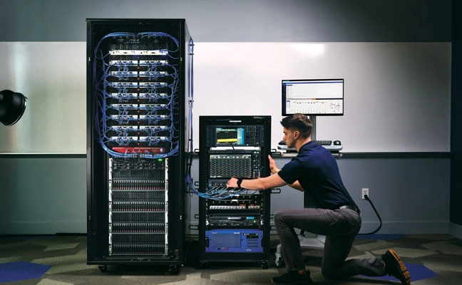
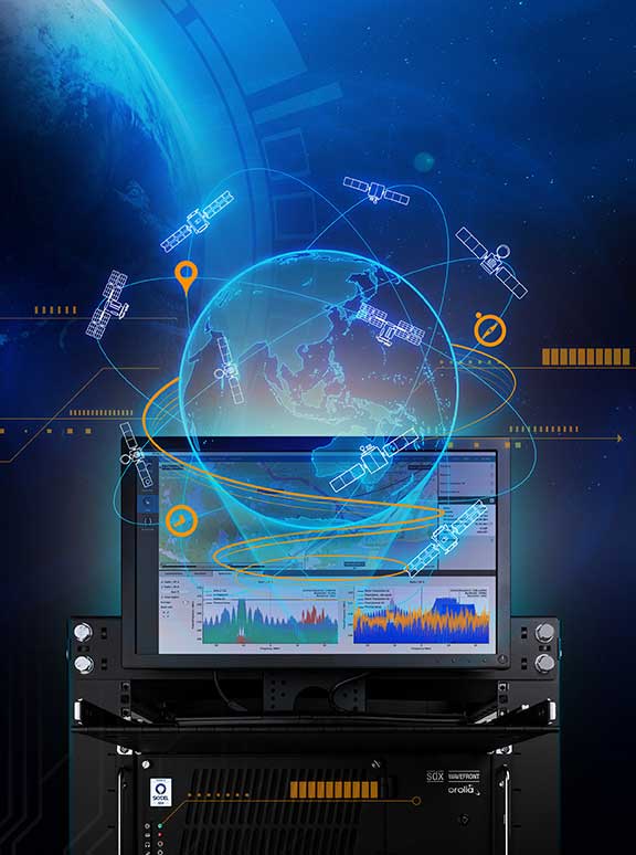
GNSS simulation has evolved well beyond accuracy testing. It now covers full-spectrum NavWar and PNT validation. Today’s simulators are expected to generate real-time GNSS, LEO signals, inertial measurement units (IMU), alternative navigation sources, jamming and spoofing — all from a single system.
“The number of signals continues to grow with the rise of multi-PNT sources and advanced threat capabilities,” said Jaemin Powell, senior product manager, NavWar & Simulation at Safran Federal Systems. “Our customers are preparing for GPS-denied operations, validating NavWar responses and ensuring resiliency in contested domains.”
Powell noted that Safran Federal developed BroadSim Genesis to enable simultaneous streaming of L1, L2, L5 and L6 GNSS and LEO signals with integrated jamming and spoofing — all within a compact 4U platform.
The company’s strategy is built on a software-defined architecture, allowing for rapid adoption to evolving threats and mission requirements, Powell said. Safran Federal collaborates closely with government stakeholders and defense primes to stay up-to-date with new requirements and incorporate real-world threat vectors, such as spoofing and jamming. The BroadSim platform supports software upgrades for every feature, from adding constellations and LEO signals to enabling hardware-in-the-loop (HIL) support or integrating additional PNT resources.
While defense and aerospace continue to serve as core markets, rising demand also is coming from space companies, LEO-PNT developers, and advanced electronic warfare laboratories now relying on Safran simulators.
“These users value the scalability, fidelity and flexibility of our simulation solutions, especially in environments with high dynamics,” Powell said. “They are looking beyond traditional GNSS, and we address that need with a simplified, all-in-one platform.
Large-Scale Simulation
“Large-scale simulation is technically demanding,” Powell added. “Generating thousands of signals across multiple bands with ultra-low latency and 1000 Hz update rates pushes both hardware and software boundaries.”
Maintaining the intuitive Skydel interface while adapting to evolving NavWar requirements remains a top priority for the company. For example, Safran Federal introduced real-time automated calibration for BroadSim Wavefront, which executes before every scenario. This allows users to power up and immediately begin testing, eliminating recalibration and setup delays.
“Simulation is more than just signal generation. It is about enabling operational confidence,” Powell said.
“Our platform gives users the ability to stress test systems, visualize behavior in real time and adapt quickly without relying on range time or live sky testing…We are enabling teams to meet their toughest NavWar and PNT challenges with confidence and flexibility. If you have demanding requirements, we are ready to deliver a solution that is intuitive, capable and built for the future.”
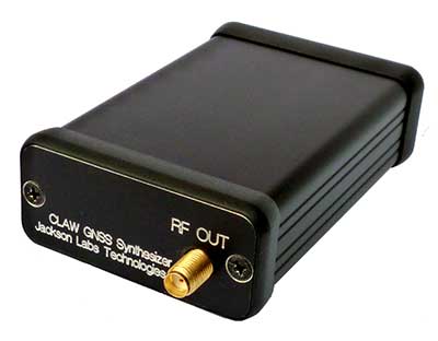
Global corporation VIAVI Solutions Inc. has completed the acquisition of Jackson Labs Technologies, a leader in positioning, navigation and timing (PNT) solutions for critical infrastructure serving both military and civilian applications.
Jackson Labs develops and supplies modules, subsystems and box-level solutions that include front-end receivers, transcoders, rack-mounted equipment, and patented retrofit technology. Their broad customer base includes armed forces, defense contractors, energy distribution infrastructure, low-Earth-orbit (LEO) operators and 5G service providers.
Jackson Labs’ next-generation M-code solutions complement and advance VIAVI’s timing and synchronization portfolio at a time when PNT requirements for defense, space, commercial aviation, transportation and telecommunication networks are expanding and becoming increasingly critical.
“As telecommunications, avionics and mission-critical infrastructure adopt next-generation technology, legacy timing and synchronization protocols are no longer sufficient. Jackson Labs is a trusted provider of PNT solutions in these markets, and we look forward to addressing these opportunities together,” said Oleg Khaykin, president and CEO of VIAVI. “With this acquisition, we are continuing to drive operational scale via the addition of advanced technology and high-performance products that address market segments with strong growth and profitability.”
“Being a part of VIAVI will significantly expand Jackson Labs Technologies’ market reach worldwide, and allow us to further deliver world-class solutions for the rapidly developing PNT landscape as it enters a new era,” said Said Jackson, CEO of Jackson Labs Technologies.
DelMorgan & Co. acted as the exclusive financial advisor to Jackson Labs in connection with the transaction. Terms of the transaction are not being disclosed.
About VIAVI
VIAVI s a global provider of network test, monitoring and assurance solutions for communications service providers, enterprises, network equipment manufacturers, original equipment manufacturers, government and avionics. It helps customers harness the power of instruments, automation, intelligence and virtualization.
VIAVI is also a leader in light management solutions for the anti-counterfeiting, consumer electronics, industrial, government and automotive markets.
VIAVI operates offices throughout North, Central and South America, Europe, Africa, the Middle East, and the Asia-Pacific, including China and Japan.
Averna and Physik Instrumente (PI) have formed a new partnership to deliver advanced automation solutions that meet the growing need for flexible, scalable and high-throughput manufacturing and test equipment.
Physik Instrumente (PI) is an international group of companies focusing on high-precision motion and positioning solutions, and Averna is a global test and quality solutions provider.
With significant overlap in several markets — industrial automation, automotive, consumer electronics, communications and life sciences — PI and Averna each offer expertise in different areas. Their goal is to expand each offering to their clients by integrating PI’s unique precision positioning and micro-robotics systems into Averna’s customized quality and assembly turnkey solutions.
To date, the two companies have delivered numerous joint projects, improving results for a variety of applications including camera and projector assembly, laser alignment, fiber alignment and optical wafer scanning.
“We are very excited to begin this partnership,” said Niels Davidts, vice president of Europe at Averna. “Having worked with PI products in the past, we understand the power of what they offer. They are unique in what they do, and we know how to make them work best for our clients. A closer partnership will open a lot of opportunities for both parties.”
Scott Jordan, long-standing photonics expert and business developer at PI emphasizes, “Working with Averna has been very rewarding. We have always been impressed with the systems they design for test, quality, and precision assembly. Combining our knowledge with Averna’s skills, we can now approach customer challenges in ways that have never been done before.”
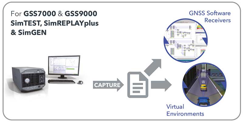
SimOSNMA provides vital test tools for Galileo’s emerging end-to-end security protocol
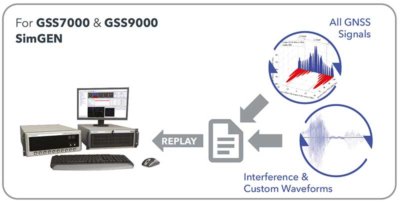
Spirent Communications plc and Qascom have announced a simulation test solution for the Galileo Open Service Navigation Message Authentication (OSNMA) mechanism.
SimOSNMA is designed to work with Spirent’s GNSS simulation platforms to test OSNMA signal conformance, which will bring new levels of robustness for both civilian and commercial GNSS uses.
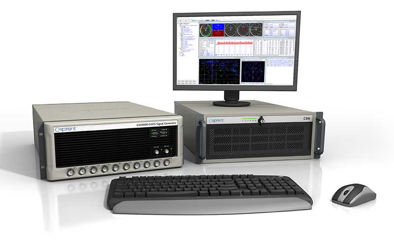
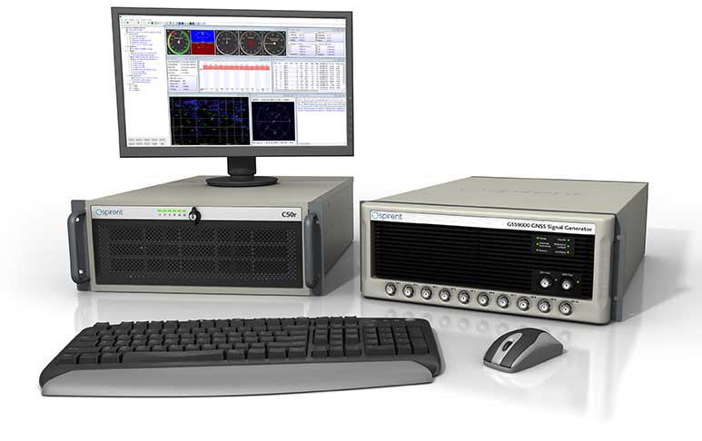
The GSS9000 test system. (Photo: Spirent)
SimOSNMA provides developers with new simulation tools to test for OSNMA, the security protocol that enables GNSS receivers to verify the authenticity of signals distributed from the Galileo satellite constellation. Designed to combat spoofing, OSNMA ensures the data received is authentic and has not been modified in any way. It is now completing the test phase before its formal launch.
SimOSNMA enables developers to simulate and test OSNMA signals and features, allowing GNSS receiver manufacturers and application developers to accelerate and assure development programs.
Qascom has been a significant contributor to the development of Galileo OSNMA. The company helped create the main test vectors for early testing and led the Position Authenticated Tachograph for OSNMA Launch (PATROL) project, which is the European Union Agency for the Space Program (EUSPA) procurement looking at the implementation of OSNMA into automotive and mass-market GNSS receivers.
“During the development of the first OSNMA receiver prototype, we needed a tool that would allow us to run tests in a controlled and repeatable environment, generate reference data, test corner cases and system events that seldomly occur in reality,” said Carlo Sarto, head of Security Engineering Domain Area. Qascom. “SimOSNMA will allow industries and agencies to speed up the development and qualification of their systems.”
Since the inception of the Galileo project, Spirent has provided crucial simulation and test capabilities to many of the key organizations and projects responsible for development of the European Space Agency (ESA) program.
SimOSNMA is available now for Spirent GSS7000 and GSS9000 platforms.
Hexagon AB has acquired CADLM SAS, a company focused on computer-aided engineering (CAE) with artificial intelligence (AI) and machine learning. These technologies enable simulation in product-development processes and lifecycles.
Founded in 1989, France-based CADLM develops computational design and optimization methods for industrial products and processes. Since 2014, CADLM has been developing AI and machine learning solutions. Its ODYSSEE software platform applies AI and machine learning to real-world sensor data and physics-based simulation data to produce accurate, predictive models of a product at efficient computing power levels.
The combination enables faster, more efficient simulations of dynamic, multi-physics phenomena — such as automotive crash and safety — that fully characterize and understand real-world product behavior. This insight enables engineers to explore the design more extensively and interactively, and improve next-generation products without prohibitive computing cost or time.
Ola Rollén, CEO, Hexagon
Use of the digital twin beyond the early design phase enables manufacturers to leverage image recognition, predictive simulation and fault prediction to address challenges such as downtime, throughput, quality and flexibility throughout the manufacturing process.
“The convergence of CAE with advances in data management, AI, machine-learning and an increasingly connected manufacturing lifecycle is transforming the industry’s ability to address increasingly complex design challenges with rapid innovation and increased productivity,” said Hexagon President and CEO Ola Rollén. “CADLM’s AI knowledge and technology further strengthen our smart manufacturing solutions portfolio, putting data to work beyond the early design phase to improve product design innovation, manufacturing productivity, product quality and environmental sustainability through reductions in material waste.”
CADLM will operate as part of Hexagon’s Manufacturing Intelligence division. The acquisition has no significant impact on Hexagon’s earnings. Completion of the transaction (closing) is subject to normal closing conditions.
For 30 years, Spirent Communications has built GPS/GNSS simulators, operating at the radio frequency (RF) level and building a broad customer base. Now, with the launch of SimIQ — which starts shipping at the end of October — the company is providing simulation at the I/Q level. (When talking about frequency mixers, the “I” stands for “in phase” and the “Q” stands for “in quadrature.”)
SimIQ is in response to requests from receiver experts, who want to be able to test their receiver algorithms earlier in the development cycle before designing the Application Specific Integrated Circuits (ASIC) or the Field Programmable Gate Arrays (FPGA).
SimIQ Capture: Record I/Q data from Spirent GNSS simulators into files. (Image: Spirent)
“They used to come up with their own individual mechanisms to generate I/Q data and test it,” said Ajay Vemuru, product line manager, NPI, Spirent. “For example, you can use programs that you develop on MATLAB to come up with I/Q data files, but that requires an effort in debugging them and keeping them up to date with the different constellations.” That effort grows as the number of GNSS constellations grows. SimIQ will use the same software as Spirent’s current simulator. However, instead of generating the RF signal, it will generate the I/Q data.
Any GNSS receiver, Vemuru explained, contains a radio that receives the RF signal and down-converts it to create a baseband digital I/Q signal. “That is the I/Q data that we are generating,” he said. “Instead of customers waiting for the RF or the ASIC to be completely designed, they can now take the I/Q straight out of our simulators, inject that into their algorithms, and run their correlators. You can run all your processing on this I/Q data without having to worry about the antenna characteristics and the front-end noise. You can pick and choose which pieces of the receiver you want to test.”
Because the software has not changed, the scenarios — such as the movement of the platform — are the same as before. Plus, customers can reuse them, running them at the I/Q level instead of the RF level.
SimIQ Replay: Generate RF with Spirent GNSS simulators from I/Q files. (Image: Spirent)
While Vemuru expects many of Spirent’s customers to be interested in SimIQ, he also anticipates new and evolving markets might take advantage of it. “There will be new teams in existing markets that we haven’t reached because they are engaging an earlier phase of the design process,” said Adam Price, director of PNT simulation at Spirent. “We want to target earlier phases in chipset development.”
In the world of autonomous vehicles, Price explained, engineers are doing significantly more simulation in software to verify more “corner cases” — jargon for problems or situations that occur outside of normal operating parameters, such as when multiple environmental variables or conditions are simultaneously at extreme levels. “As you start to get into safety-critical systems, for example, software simulation is becoming increasingly required,” Price said. “This could allow us to engage that segment. People want to carry out verification earlier in the design cycle.”
By running a simulation in hardware and presenting the devices being tested with a real RF signal, Price points out, engineers are limited to operating in real time. By contrast, in software they can run simulations faster or slower than in real time and even run several simulations in parallel. This is important for developing autonomous vehicles because engineers need to test many scenarios over millions of miles of simulated travel.
Spirent’s SimIQ, however, is addressing a somewhat different market, Vemuru said. “In fact, they would prefer to run slower than in real time because their ASIC or FPGAs are not yet in production. So, they would be essentially running them on CPUs, which take a lot more processing time.”
So far, we have been talking only about capturing I/Q data. However, SimIQ can also replay it. This, Vemuru said, “is essentially for customers who want to add interference patterns that, for some reason, they don’t want Spirent or anybody else to see. It can be any signal, so long as it is within the frequency of the GNSS spectrum. They can inject I/Q files into the platform itself. We take the external I/Q stream, generate the GNSS signals, add them up, and generate this at the RF level.”
One use case deals with classified signals. “They can always generate baseband I/Q data of that classified signal, as a file, and inject it into our simulator, so that we can generate the RF signal for that particular classified I/Q signal alongside the GNSS that already comes out natively from our boxes,” Vemuru explained.
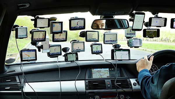
This tongue-in-cheek photo, courtesy of Racelogic, underlines how simulators help GNSS engineers “road test” multiple positioning products in multiple scenarios. (Photo: Racelogic)
The number of GNSS signals, the frequency and sophistication of intentional and unintentional threats to those signals, and the need for integration between GNSS and other positioning, navigation and timing (PNT) sources — especially for indoor and autonomous navigation — are continuing to increase, as is the number of new applications for GNSS. In response, manufacturers of GNSS simulators are creating new and improved models able to simulate all these new signals and scenarios.
Additionally, as GNSS chipsets continue to be further commoditized, simulator manufacturers must address the needs of new entrants into the GNSS receiver market that have lower accuracy requirements and require less technical expertise and, therefore, require units that are smaller and cheaper and have simpler interfaces.
No single manufacturer can address the full spectrum of challenges that these trends present. So, while their products overlap in capabilities and SWaP-C (size, weight, power and cost), each one has chosen its market niche and preferred mix of features.
Even on the deceptively simple question of definition (“What is a GNSS simulator?”), the seven manufacturers featured here give different answers, covering the following capabilities:
Simulating GNSS signals as well as inertial navigation data.
Enabling users to test hardware, software and new solutions in the lab before deployment.
Enabling users to test systems under pristine or extreme conditions, including error conditions.
Enabling users to test systems during rare, transitional and prohibited events.
Helping to retrofit existing equipment to new and emerging standards.
Innovations being introduced or developed include:
an anechoic simulator to test continuous radiation pattern antennas (CRPAs).
simulation of a full M-code modernized signal.
software-defined simulators.
increased automation of repetitive tasks.
the capability to record and replay real-world signals.
the capability to record and synchronize data on the conditions faced by a test vehicle.
While the universe of GNSS satellites and receivers continues to grow and evolve, the universe of GNSS simulators is keeping pace — or even a step ahead.
Click on the company to be directed to that section.
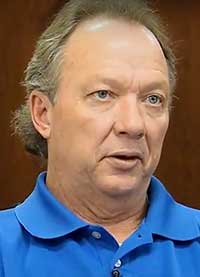
John F. Clark, Vice President, Engineering. (Photo: CAST Navigation)
In the lab, simulators allow users to “drive” a piece of equipment through 3D space, performing flight testing or checking equipment integration. Simulators also validate operational flight programs (OFPs) for pilots before they are fielded, to ensure that the software is working correctly.
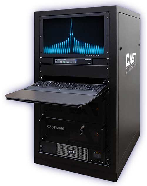
Innovation. CAST’s latest simulator is the CAST 5000 wavefront generator. It allows users to drive GNSS and interference signals that represent a continuous radiation pattern antenna (CRPA), which consists of multiple, smaller antennas all combined into one unit. In real life, each one of those antenna elements is in a different location; therefore, when they receive signals from a jammer or any of the GNSS satellites, each one will see that signal in a slightly different phase from the other elements. “Our simulator allows us to present signals to these antennas that model the same type of phase differentiation that you see in real life,” Clark said.
Photo: CAST Navigation
Coming Next. CAST Navigation is constantly improving its software based on user feedback. “We are in the process of enhancing our user interface to make it much more powerful but also much simpler to use,” Clark said. Hardware is also being improved, with implementation of the latest available GNSS always on the list.
Looking Ahead to 2022. Jamming and spoofing are becoming more prevalent, not just for the military but also for consumers. Consumers are starting to encounter more instances of jamming, denying their phone the ability to track a GPS satellite or transmitting incorrect GPS data so the solution that their device gives them is not correct. “Our focus is on products and capabilities that help our customers simulate those types of environments and mitigate those kinds of reactions,” Clark said.
Jackson Labs Technologies Inc.
Said Jackson, President and CTO. (Photo: Jackson Labs)
Jackson Labs’ simulators take a position, navigation or timing signal, re-encode it into an RF signal through a GPS simulation procedure, and output a real-time RF signal that encodes the position, navigation and timing (PNT) information, within milliseconds, into an RF signal that can be fed into existing equipment. “We came up with a general-purpose simulator that is basically a no-frills, low-cost, highly accurate, highly stable, highly reliable, extremely small GPS-only simulator,” explained Jackson. “We only provide GPS L1 simulation, to keep the cost of the product down, because GPS L1 C/A code is the only code required to generate an accurate and assured PNT fix, and because we are looking at simulating to embedded systems, where you only need an L1 C/A code simulator.”
Photo: Jackson Labs
Coming Next. Jackson Labs’ simulators don’t require an external computer for data processing or control. That makes it possible for companies like Toyota to plug the unit into a car on the assembly line, and generate RF output that is fed into their GPS-based navigation systems to pass final quality-assurance checks on the production line. Jackson Labs expects to further reduce SWaP-C (size, weight, power and cost) requirements and potentially add other signals. “We are also looking to potentially combine our simulators with other product lines that we have, such as our comprehensive atomic clock product line,” Jackson said.
Looking Ahead to 2022. Jackson predicts that the sector will split into two paths: an industrial sector with units for manufacturing and deployment, and companies that introduce emerging GNSS systems at much lower price points, smaller SWaP, and with more modular deployment. Inertial navigation systems (INS) are critical for autonomous driving and assured capabilities during spoofing and jamming events, Jackson said. “It is not possible today to very easily simulate INS units.There is a market for innovation in terms of integrating what the military calls ‘assured PNT,’ which includes things like dual navigation.”
Orolia
Stéphane Hamel, Director, Testing and Simulation. (Photo: Orolia)
According to Orolia’s Hamel, a simulator’s purpose is two-fold: first, it must reproduce threats and second, it must prove the solution is working.
Innovation. When Skydel Solutions joined Orolia in March, it brought a professional software-defined simulator that makes possible fast prototyping and development cycles. It integrates advanced interference simulation and can simulate hundreds of threats simultaneously. “When you want to do a repetitive step, automation is the key,” Hamel said. “Our simulator can teach you how to automate, just by clicking on a button and generating source code.” In 2018, Skydel introduced an anechoic simulator to test Controlled reception pattern antennas (CRPAs). Also new is a waveform simulator, so CRPA units can be tested in a conducted (rather than radiated) way.
Image: Orolia
Coming Next. In the next three years, Orolia is looking at adding Galileo PRS, GPS M-code, or the next-generation signal. “Being software-defined means that we are very flexible and we can allow our partners to develop their own plug-ins,” Hamel said. “They can build custom signals, restricted or modernized signals. Our simulator will take care of the dynamics of the signal and our partners can focus on the characteristics of the signal, or the things that are secret, classified, or if they simply want to protect their IP.”
Looking Ahead to 2022. Resilience to serious spoofing and jamming threats is high on Orolia’s list, as well as ensuring secure or valid positioning, navigation and timing (PNT) in GPS-denied environments. Alternative signals, sensors and increased complexity require a simulator to address all of these. Companies that develop complex proprietary hardware platforms will be challenged to keep up with the increasing complexity. and a software-defined approach will be an advantage.
Racelogic’s first LabSat was a recorder with player — the signals were recorded outside, and then replayed in the lab. Racelogic’s simulators now also provide simulation of the signals using software to generate the signals as though they are being sent by the satellites.
Innovation. In 2018, Racelogic introduced the LabSat wideband, which uses the company’s SatGen software. It records at 56 MHz and up to 6 bits of resolution and streams the data to an internal SSD hard drive. It can also replay real-world simulations or ones generated with SatGen. For the automotive world, it records and replays signals such as CAN, RS232, RS485, IMU and other data channels, synchronizing them at the same time. VBOX allows users to record and replay video with the perfectly synchronized recording made on the LabSat. “You see exactly the kinds of conditions of the test vehicle or person who has been subjected to the test,” Thomas said.
Photo: Spirent
Coming Next. Racelogic is providing wider bandwidth, greater bit depth, and multiple channels in a small battery-powered device that records even more signals, including lidar, EtherCAT (an automotive Ethernet format) and CAN-FD (a faster version of the CAN format). It will be able to synchronize with multiple video cameras instead of just one in high resolution. “It is basically the same as what we are selling, but on steroids, and at a very similar price point,” Thomas said.
Looking Ahead to 2022. With multi-GNSS going mainstream, both chip manufacturers and simulator manufacturers will be challenged by the cost of test equipment. Chip makers need to be able to test the new signals on their production lines, while simulator makers will need to provide devices at a price point and ease of use for customers with less stringent or slightly less technical requirements. “They need a simpler interface and a smaller, cheaper unit,” Thomas said.
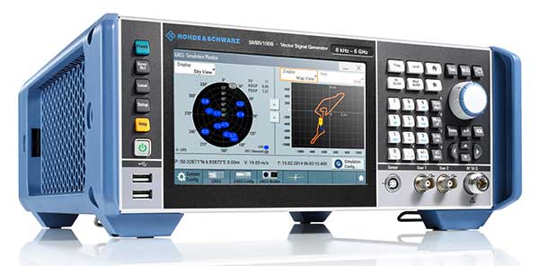
Rohde & Schwarz
Markus Irsigler, Product Manager, Signal Generators. (Photo: Rohde & Schwarz)
An increasing number of GNSS applications depend on multi-frequency GNSS.
Innovation. In response, Rohde & Schwarz added multi-frequency test capabilities to its entry-level and mid-range test solutions. “We have launched a new GNSS simulator based on the new mid-range vector signal generator R&S SMBV100B,” Irsigler said. A simple and flexible option concept allows users to turn the instrument into a full-featured and powerful GNSS signal source. It addresses a wide range of test applications, from single- and multi-frequency production testing to multi-frequency receiver characterization. The instrument can be equipped with an internal noise generator that allows users to simulate GNSS plus noise or CW interference without using additional external hardware.
Photo: Rohde & Schwarz
Coming Next. GNSS test solutions from R&S are based on general-purpose vector signal generators. With this approach, GNSS and other signals can be generated at the same time in the same instrument allowing coexistence and interference testing without additional external signal sources. As this results in test solutions that are compact and very flexible to use, R&S will continue to use this approach for upcoming product upgrades and enhancements as well as for its next generation of GNSS test solutions. The company’s upcoming activities will mainly focus on the high-end segment, where the R&S SMW200A with up to 4 RF outputs and up to 144 channels addresses multi-antenna and multi-vehicle GNSS test applications.
Looking Ahead to 2022. With the safety demands of autonomous driving or aircraft landing procedures, multi-frequency testing will become standard. Because such applications must be sufficiently robust against spoofing and jamming threats, there will be an increasing need to test navigation systems against such influences. “Simulating GNSS alone is not enough,” Irsigler said. “Test solutions for autonomous driving will require several other techniques and signals to be applied or simulated, such as RTK/PPP or outputs from other vehicle sensors to perform sensor fusion.”
Spirent Federal Systems
Roger Hart, Director of Engineering. (Photo: Spirent)
Spirent’s simulators test with “real-world” signals as well as allowing tests under pristine conditions or under extreme conditions that may never occur in the real world, including error conditions.
Innovation. In December 2018, Spirent released the SimMNSA, which provides a full M-code modernized signal solution. Until now, the GPS Directorate limited M-code simulation to either pseudo-M-code, which provides the same spread-spectrum but uses a commercial encryption standard, or a system of playing back a canned set of M-code limited to certain satellites and dates and times. With the policy change, Spirent can now implement M-code based on the modernized Navstar security algorithm (MNSA), and now offers both an M-code solution with the SimMNSA and a full Y-code with the SimSAAS.
Jeff Martin, Director of Sales. (Photo: Spirent)
Coming Next. Spirent plans to provide customers an increased channel count to help test multi-constellation, multi-frequency receivers against multipath, jamming and spoofing. “We are in a period of intense development in terms of AVs, UAVs, and so forth, which don’t use GNSS exclusively,” Hart said, explaining that Spirent is working on testing of GNSS/sensor-fusion platforms.
Looking Ahead to 2022. “As new interface specifications are released, we are proactive in developing new signals,” Hart said. Spirent also is supporting efforts to achieve assured PNT solutions. It is investigating interference-mitigation techniques such as algorithms, directional antennas, and other anti-jam technologies. Signal authentication is another need. “As the systems are becoming more integrated and networked, we are conscious of cyber-security threats and are looking in that area,” Hart said.
Photo: Spirent
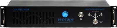
Syntony GNSS
Cyrille Gernot, GNSS Receiver Development and Product Manager. (Photo: Syntony GNSS)
GNSS receiver manufacturers use simulators to ensure that their products are robust in challenging situations that can’t be clearly assessed using real-world data. “That’s where the GNSS simulator comes into play,” Gernot said, “by offering controlled and repeatable scenarios.”
Innovation. Syntony’s new pseudo-random-noise code (PRN code) server allows the GNSS simulator user to dynamically send the pseudo-random sequence modulating a carrier. It is especially useful for testing encrypted signals such as the GPS military signal or the IRNSS RS signal. “Access to encryption keys is extremely difficult for a simulator manufacturer to obtain,” Gernot said. “However, the simulator does not actually need to have knowledge of those encryption keys; only the resulting pseudo-random sequence to modulate is required.” The Syntony PRN server allows users to dynamically input their own pseudo-random sequences to be modulated on the target carrier into the simulator.
Coming Next. Syntony’s next simulator will simulate spoofing and synchronous multi-antenna signals for CRPA and antenna network testing.
Photo: Syntony GNSS
Looking Ahead to 2022. As the threat of spoofing and jamming increases, the receiver industry will have to develop countermeasures and mitigation strategies. One of the best methods remains the use of antenna arrays, Gernot said. “Antenna arrays allow for spatial discrimination that is especially efficient to counter spoofing, jamming or unintentional interferences.To meet the industry’s future demands, Syntony is already working on accurate simulation of antenna arrays while accounting for inherent errors such as inter-antenna phase and amplitude offsets and overcoming obstacles, including phase coherency at the output of the simulator RF channels.”
The new portfolio offers a comprehensive array of GNSS validation technology, as well as signal and PNT data protection through jamming/spoofing detection, suppression and countermeasure solutions.
The capabilities are built on Orolia’s legacy of resilient PNT solutions, together with two key acquisitions completed this year: Skydel Solutions and Talen-X. These companies were selected based on their demonstrated GNSS testing and simulation experience.
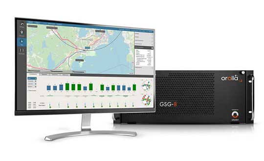
GSG-8, the latest advanced simulator from Orolia, was also introduced to the global GNSS community this week at ION GNSS+. This software-defined simulation solution offers ultra-high performance and unmatched flexibility in an easy-to-use format. GSG-8 was developed to deliver the highest standard of GNSS signal testing and sensor simulation performance, in an upgradable and scalable platform.
“With its scientific precision and advanced simulation capabilities, GSG-8 is revolutionizing the GNSS simulation industry with Orolia’s robust 1000Hz Skydel software engine and COTS software-defined radios,” said Stephane Hamel, director of testing and simulation at Orolia. “GSG-8 is designed for customers that require complex capabilities to validate product and program performance in harsh, high risk environments where failure is not an option- such as government agencies, space programs and specialized commercial programs.”
It can be programmed to simulate operations with multiple GNSS constellations and to incorporate the use of encrypted or proprietary signals. GSG-8 can also be configured for Wavefront and Anechoic chamber simulation protocols to test anti-jam antennas and complete systems, to serve the most challenging program requirements.
3D modeling solution creates true-to-life synthetic environments for more accurate testing.
Spirent Communications plc has launched an innovative multipath simulation solution, Spirent Sim3D. The 3D modeling solution enables the testing of realistic multipath and obscuration effects on GNSS signals in a true-to-life synthetic environment.
Sim3D is suitable for use by automotive, chipset, handset and receiver manufacturers, as well as in aerospace, military, mining and precision agricultural applications.
Spirent will demonstrate Sim3D at ION GNSS+ 2019 in Miami, Florida, Sept. 16-20.
Studying multipath. Historically, researchers and developers of GNSS receivers have had to rely on statistical models and time-consuming field testing to study the effects of multipath on GNSS signals.
With Sim3D, the industry can now gain a greater understanding of the impact of multipath and obscuration in a broad range of real-life situations. It offers the level of control and traceability needed for developers to improve their customers’ experience in the most challenging environments.
A satellite signal reflecting off surfaces, such as a building, a high-sided vehicle, a tree, or even the ground, alters the pseudorange, causing the signal to arrive at the receiver slightly later than line-of-sight signals.
Without proper mitigation, this can cause a receiver to output an inaccurate position.
“Obscuration and multipath effects are one of the major obstacles faced by engineers trying to achieve accurate GNSS positioning solutions,” said Spirent Managing Director of Positioning Martin Foulger. “The accelerating development of connected autonomous vehicles and other precision applications means the need to test for higher precision positioning, navigation and timing in a variety of environments is growing rapidly. Sim3D is an important and timely development.”
Image: Spirent
Simulation of 3D environments. The unique system has been developed in partnership with OKTAL Synthetic Environment. It offers the ability to simulate multipath effects in a range of lifelike geo-typical environments, using different models to recreate locations such as urban highway, an inner city or a forest. Geo-specific models of real locations can also be commissioned.
During simulation with Sim3D, the GNSS signals interact with fully customizable 3D environments to simulate real-life applications in operation, like a vehicle on a highway, or a wearable device on a pedestrian.
This gives a level of detail, control and realism in testing not previously available. Such realistic multipath and obscuration simulation will add greater credibility to GNSS testing and assure that developed solutions are optimized and tested for their intended environments.
“As vehicles become increasingly autonomous, it’s vital to get a more detailed understanding of the effects of obscuration and multipath on a vehicle’s ability to generate an accurate GNSS-based position” explained Foulger. “Statistical models cannot sufficiently achieve this.
“Sim3D’s ability to realistically simulate different environments provides this greater accuracy and brings a host of benefits to researchers and developers of autonomous vehicle systems,” Foulger said. “It will help to guide critical design decisions like where to place the GNSS antenna on the vehicle, what GNSS receiver to use and when to hand over to other position sensors as GNSS signals degrade.”
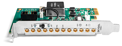
Skydel has released a new clock distribution module for the GNSS industry.
Photo: Skydel
Designed in a PCIe card format, the CDM-5 is a compact and precise clock intended for use with GNSS and other RF systems. It can synchronize up to five devices and can be integrated into custom hardware systems.
Skydel’s CDM-5 provides 10-MHz and 1-PPS signals for up to five devices that need tight and precise synchronization. It is suitable for PCIe-based software-defined radios (SDR) installed in rackmount or desktop PCs, and also can be used for any other applications that require a precise PC-based timing reference.
Skydel’s CDM-5 clock distribution module features two operating modes—internal or external— that are selected with the bracket-mounted switch.
In internal mode, the CMD-5’s internal clock signal is extracted from the onboard high-grade oven-controlled crystal oscillator (OCXO).
When operating in external mode, CDM-5 accepts input signals in the form of 10-MHz and 1-PPS, which are then redistributed via five matched-length traces. Split signals are amplified to maintain the power level across all distributed paths.
Additionally, CDM-5 will regenerate 1 PPS from an external 10-MHz-only source if a 1-PPS source is not available.
The CDM-5 can be integrated into a custom assembly by removing the bracket plate and powering the board through its 12V DC connector. When the bracket is removed, the operating mode can be toggled using the onboard switch.
Key features:
Timing and frequency source with five-way distribution of 10-MHz and 1-PPS signals
PCIe form factor for rackmount or desktop PC
Two operating modes: internal clock (OCXO) or external clock (10MHz and 1PPS)
Supports standalone operation with 12V DC power supply
By Tommaso Panicciari, Mohamed Ali Soliman and Grégory Moura
All images provided by the authors
A real-time system combining a simulator and a GNSS propagation model reproduces an authentic multipath environment. The propagation model relies on a 3D-model reconstruction of the urban environment, which generates a multipath signature strictly dependent on the location of the receiver’s antenna. This yields important results for a moving vehicle, which may be affected by very different multipath conditions depending on trajectory and location.
Positioning and navigation can be degraded in urban environments by multipath, and the error can increase considerably if not properly compensated. In situations where the line-of-sight (LOS) is obscured by surrounded buildings, the receiver may still be able to navigate by using the non-line-of-sight (NLOS) signal, which originates from single or multiple reflections/diffractions of the GNSS signal.
The use of 3D models has been one of the preferred solutions to recreate the multipath environment as seen by a GNSS device. This solution brings the capability to generate a multipath signature that is representative of the position of the antenna in a specific time and space. However, this solution comes with a certain degree of complexity. In fact, an accurate 3D model is required to simulate the obscuration of the GNSS signal, and a good propagation model is needed to generate phenomena like reflection and diffraction.
Figure 1. Example of propagated signal simulation. (Image: Tommaso Panicciari, Mohamed Ali Soliman and Grégory Moura))\
3D models have become more accurate and widely available and are mainly used to predict the satellite availability in specific locations, for example in evaluating the signal availability in urban canyon, and for both reflection and diffraction. Other uses of 3D models are as an aiding tool to assist navigation, sometimes together with an INS solution.
In this article, we present a novel real-time system capable of simulating realistic multipath in different environments. The system can simulate multiple GNSS constellations and is comprised of a GNSS simulator interfaced to a propagation model. The system can create a whole range of signals, effects, error models and trajectories in a real-time closed loop. The propagation model controls the simulation of multipath from the interaction of the GNSS signal with the 3D scene and objects. This article describes a novel real-time system for the simulation of realistic multipath in different environments and compares simulated and field-test data. The comparison is based on signal availability, horizontal error, carrier-to-noise (C/N0), pseudorange and Doppler residuals.
RAY-TRACING WITH 3D MODELING
The model simulates the propagation of GNSS signals in constrained environments, considering obscurations and multipath. It uses a proprietary ray-tracing kernel (based on bounding volume hierarchy techniques using processing unit [GPU] resources) coupled with geometrical optics and uniform theory of diffraction to compute the interaction between the signal and the local environment. The computation uses as main input a synthetic environment (that is, geometrical and physical modeling of a real or realistic environment) to assess the impact of obscurations related to signal availability issues and multipath (the cause of fading effects and performance problems).
The objective of ray-tracing is to find all the possible paths from the observer to the source of the signal considering a limited number of interactions per emitted rays. A ray-tracer (or ray-tracing algorithm) uses a primary grid to cast primary rays. Then, it iteratively computes the possible interactions between these rays and the virtual scene (often defined using triangles). If those interactions exist (if they comply with the law of physics) and if the number of interactions to reach the emitter is below the maximum number of interactions set by the user, then a ray (or multipath) is created. This is a deterministic method that can be used to calculate the obscuration due to the local environment (and therefore detect the signal availability) and the geometrical characteristic of the computed path. Combined with physics modeling, path attributes such as received power, delay, Doppler, and phase are also provided.
The main characteristics of ray-tracing techniques to model GNSS propagation are:
All the signals arriving at the receiver can be model-based on the virtual environment.
As it is a deterministic method, the more realistic the environment modeling, the more compliant with reality the results. Moreover, the simulation results are repeatable.
The specular multipath can be displayed in 3D, and the attributes (for example, receiver power, phase, polarization, Doppler, geometry of the ray) are known. For example, this is relevant when the effect and signature of the environment on the propagation signal need to be studied and understood.
Nonetheless, ray-tracing techniques must account for three major difficulties:
They are time-consuming algorithms. Indeed, depending on the complexity of the scene (defined in terms of the number of triangles), a combinatorial problem to find the possible multipaths reaching the receiver makes the ray-tracer very resource-demanding. That is the reason why the most difficult task to achieve during the coding of a real-time ray-tracing algorithm is to develop acceleration techniques to quicken the computation process. Several solutions exist to either improve the intersection determination (for instance, based on spatial hierarchies such as bounding volume hierarchy [BVH] techniques), or to decrease the number of cast rays (often based on adaptive sampling techniques), or even to replace rays with beams or cones. Moreover, it is possible today to use the resources of graphic boards to accelerate the computation. Indeed, as ray-tracing can be coded by a large number of primary functions that can be treated simultaneously, it can be easily ported into GPU.
Their accuracy depends on the resolution of the primary grid. Details and therefore rays may be missed if the 3D scene is made of small details. This issue is called aliasing. Aliasing artefacts are raised for instance in parts of the scene with abrupt changes (such as edges) or in complex areas with lots of constituent objects. Solutions (or antialiasing techniques) exist to overcome this issue such as adaptive or stochastic samplings.
When it is combined with geometrical optics, these algorithms only compute the specular rays. Even if some techniques exist to model the scattering signals, only physical optics can render the global signal with high fidelity.
MULTIPATH SIMULATION SYSTEM
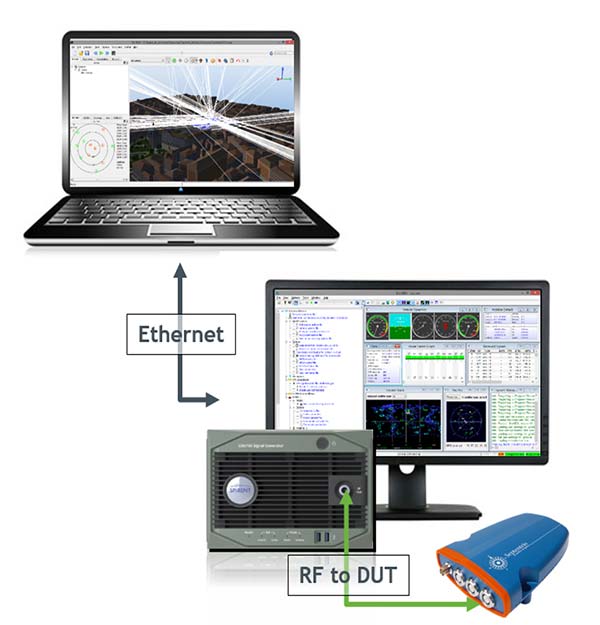
The proposed system can model two of the main propagation issues encountered in urban environments, such as obscuration (which leads to limitations in signal availability) and multipath (which generates interference that causes fading of the signal and positioning errors). To model realistically such a complex phenomenon, the system uses a GPU ray-tracing algorithm combined with geometrical optics and uniform theory of diffractions. The ray-tracing algorithm relies on 3D-model reconstructions of the urban environment. The computed obscuration and multipath effects are then used to generate signal corrections (in terms of power, delay and Doppler variation) to be used in the GNSS simulator, which generates the carrier, code and navigation messages for different GNSS constellations into a single RF output. Some of the advantages of this system is its ability to run in real time, and to visually show all the reflections/diffractions of the GNSS signals that cause multipath interference.
Figure 2 shows the diagram of the system set up in conductive mode. The system includes a SE-NAV PC controller, simulator software suite controller, GNSS simulator and device under test (DUT). A different mode is also available called over the air (OTA). This mode uses an anechoic chamber and a set of antennas distributed uniformly to generate the RF signal including the multipath. The DUT can then be placed at the center of the chamber and will be able to receive LOS and NLOS signals from different angles of arrival.
Figure 2. System diagram that shows propagation simulator controller (top), the GNSS simulator (bottom) and the device under test connected to the RF output of the simulator. (Image: Tommaso Panicciari, Mohamed Ali Soliman and Grégory Moura)
The GNSS simulator software suite is used to generate and control the generation of the satellite signals (including multipath) at RF, whilst the propagation simulator is used to calculate the propagation information (delay, Doppler and attenuation) of the reflected signals through a 3D urban model. The propagation software is interfaced with GNSS simulator software by means of a package of remote-control facilities that greatly enhances the flexibility of the propagation simulator. Those commands can be sent and received through the transmission control protocol/use datagram protocol (TCP/UDP) with different data streaming rates (10 Hz was used for this article).
It is also important to point out that the propagation simulator computes all the possible multipath signal generated by the 3D model given the position of the satellites and receiver. However, the physical limitation of the number of channels in the simulator causes the rejection of some rays. This rejection or filtering process can be done according to power (used in this article) or delay.
EXPERIMENT SET-UP
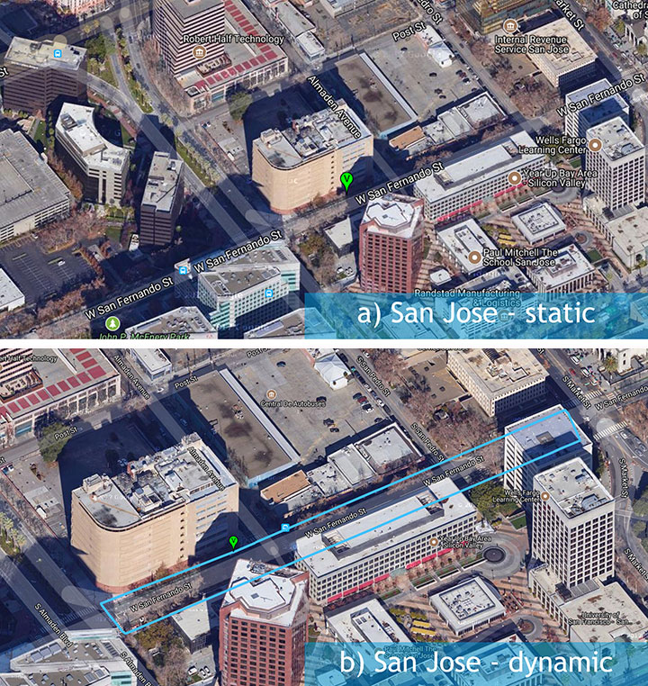
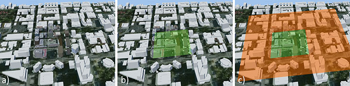
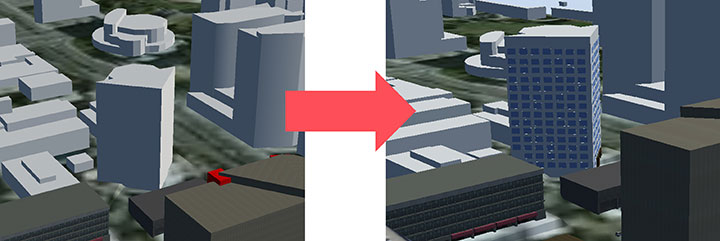
A set of different field-test campaigns where carried out in August 2016. Each campaign aimed to evaluate the ability of the system to assess the performances of a GNSS receiver using simulated signals in urban environments. Figure 3 shows the trajectory (blue line) used for the experiment in an urban environment — San Jose, California — with a static (a) and dynamic (b) scenario.
Figure 3. A set of three measurement campaigns where carried out during Aug. 9–10, 2016: a) urban environment with static antenna; b) urban environment with dynamic antenna. (Image: Tommaso Panicciari, Mohamed Ali Soliman and Grégory Moura)
Figure 4 shows the 3D scene used to replicate the San Jose urban environment. The buildings in close proximity of the antenna (green area in Figure 4b) contain details like material, 3D facade and windows. In contrast, the buildings far from the antenna were only corrected for height, and the material was modeled as concrete only.
Figure 4. The San Jose model contained most of the details around the receiver antenna (b), with only height corrected for buildings far from the antenna (c). (Image: Tommaso Panicciari, Mohamed Ali Soliman and Grégory Moura)
An exception was made for one building in San Jose because its complex architecture was believed to contribute to more reflected rays than would a more simplistic box (concrete) model (Figure 5).
Figure 5. Improvement (right) in one San Jose building because its complex architecture was believed to generate more reflections than the more simplistic box model (left). (Image: Tommaso Panicciari, Mohamed Ali Soliman and Grégory Moura)
EXPERIMENT RESULTS
A direct comparison of C/N0 power, pseudorange residual, and Doppler residual was performed between the field test and simulation.
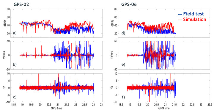
San Jose Static Results. Figure 6 shows the results obtained from the San Jose static scenario for satellites PRN02 and PRN06: C/N0 ratio, pseudorange residual and Doppler residual for field test (blue line) and simulation (red line). Although the simulation sometimes creates deeper fading than in the field test, a first comparison indicates a good correlation of simulated data with field-test data.
Figure 6. Carrier-to-noise ratio (top), pseudorange residual (middle) and Doppler residual (bottom) for PRN 02 (left column) and PRN 06 (right column). (Image: Tommaso Panicciari, Mohamed Ali Soliman and Grégory Moura)
The signature of the multipath caused by this urban environment is visibly captured in the simulation. More interestingly, the pseudorange residuals and, to a lesser extent, Doppler residuals also indicate that the model is replicating the dynamics of the multipath environment in close correlation with the field test.
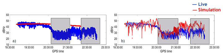
Figure 7 shows the C/N0 obtained from the field data (blue), and simulated data (red) with only obscuration (a) and with obscuration and multipath (b) for the static scenario.
It can be noticed that the receiver can still track PRN02 without the LOS, therefore, relying on just the NLOS signal. This can be clearly seen in Figure 7a where a sudden drop in power is associated to an obscuration of the same satellite (based on our 3D urban model).
Figure 7b shows the C/N0 obtained from the simulation (red line) when both obscuration and multipath were enabled. In this case the receiver could track the satellite even in the case of only NLOS as in the field test.
Figure 7. Carrier-to-noise ratio for satellite PRN02 with only obscuration (a) and with multipath (b). (Image: Tommaso Panicciari, Mohamed Ali Soliman and Grégory Moura)
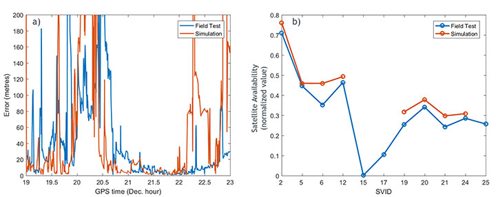
The positioning error for the San Jose static scenario is shown in Figure 8a. The simulation and field-test data have a comparable error. The error is relatively big at the beginning of the simulation and decreases after time 20.6. At the time 22.3, a moderate increase in the positioning error is visible in the field data until the end of the test. The simulation also shows a similar trend in this last part of the test, but tends to generate a higher positioning error.
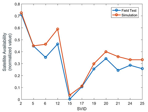
The satellite availability is shown in Figure 8b for both simulated (red) and field test (blue). The availability of the satellites generated with simulated data is in close relationship with the field data. However, some satellites could not be tracked in the simulation.
Figure 8. a) positioning error for field-test (blue) and simulation (red); b) satellite availability for field data (blue) and simulation (red). (Image: Tommaso Panicciari, Mohamed Ali Soliman and Grégory Moura)
The importance of the accuracy of the 3D scene is evident in this example. In fact, we noticed that one of the buildings that was simulated as a simple concrete box was more complex in the real environment. Therefore, we applied some modifications to scene, as in Figure 9.
Figure 9. 3D scene improvement. (Image: Tommaso Panicciari, Mohamed Ali Soliman and Grégory Moura)
After those changes, a general improvement in the results was visible, but most importantly, the missing satellites could finally be tracked by the receiver (Figure 10).
Figure 10. Satellite availability for field data (blue) and simulation after scene improvement. (Image: Tommaso Panicciari, Mohamed Ali Soliman and Grégory Moura)
SAN JOSE DYNAMIC TEST RESULTS
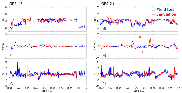
Similar results were obtained with the dynamic test in San Jose. Figure 11 shows the results obtained for satellites PRN12 and PRN24. The walking trajectory included two points where the antenna was stopped because of a traffic light. Those points correspond to a relatively flat C/N0 that can be clearly seen in the field test and simulation data for both PRNs. When, instead, the antenna was moving, a higher variation in the C/N0 is noticeable in both simulation and field test.
Figure 11. Carrier-to-noise ratio (top), pseudorange residual (middle), and doppler residual (bottom) for PRN 12 (left column) and PRN 24 (right column). (Image: Tommaso Panicciari, Mohamed Ali Soliman and Grégory Moura)
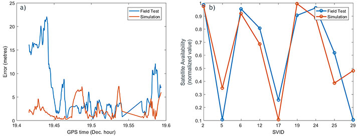
Figure 12a illustrates the positioning error obtained from simulated (red) and field test (blue). The first part of the simulation produced an error smaller than the one obtained from field data. However, from the time 19.48, a good agreement can be seen. The satellite availability is also shown in Figure 12b. This last result was obtained with the improved model described in Figure 9.
Figure 12. (a) Positioning error for field-test (blue) and simulation (red); (b) satellite availability for field data (blue) and simulation (red) after scene improvement. (Image: Tommaso Panicciari, Mohamed Ali Soliman and Grégory Moura)
CONCLUSIONS AND FUTURE WORK
A new real-time system for multipath simulation is designed to generate realistic multipath that depends on time, position and type of urban environment. The 3D scene is used to calculate the multipath (reflection and diffraction) caused by the buildings and objects around the antenna.
Some first results demonstrated that realistic multipath can be generated by simulating reflections and diffractions even with a simple 3D model. However, the inclusion of finer details in the model can improve the simulation and make it even closer to reality.
As always, simulation interest is a tradeoff between reliability in all conditions and efforts to adapt (that is, to specify) a generic and simple model. The added value of our model consists in its simplicity and its good compliance with field data.
Ray-tracing techniques coupled with geometrical optics and uniform theory of diffraction are efficient and simple methods to simulate the propagation of GNSS signals in complex urban environments. Their efficacy is demonstrated by a good agreement between simulation and field measurements. Some discrepancies still exist and are due to the limitations of such a model:
The accuracy of the model is never perfect and, as ray-tracing is a deterministic method, the returned results strongly depend on the quality of the input data used to generate the model.
Geometrical optics is a simple (but efficient) method. Only specular rays are modeled, thus the system won’t be able to generate all the signals coming from other phenomena such as scattering. Another limitation is given by the hardware. In fact, the number of simulated multipath depends on the number of available channels in the simulator.
The simulation parameters try to mimic the field conditions. However, the simulated trajectory is approximated, and other factors like pedestrian motion, vegetation (isolated trees or forest) and traffic may contribute to reduce some of the discrepancies that can be observed between simulation and field
All of these limitations can explain the differences between simulated and measured data. Currently, the impact of vegetation (forest and/or isolated trees) models, pedestrian motion and traffic on the multipath signal can also be simulated and their performances are under evaluation.
ACKNOWLEDGMENTS
We thank Colin Ford and Ajay Vemuru from Spirent Communications and Antoine Boudet, Yann Dupuy, Arnold Duquesne and Paul Pitot from OKTAL Synthetic Environment.
MANUFACTURERS
The system described in this article consists of a Spirent GNSS simulator equipped with a SimGEN software suite and the SE-NAV simulator developed by OKTAL Synthetic Environment. SE-NAV is interfaced with SimGEN via the SimREMOTE protocol, a real-time control and motion API.
Tommaso Panicciari obtained a Ph.D. in telecommunications from the University of Bath (UK). He is a software/project engineer at Spirent Communications where his main activity focuses on spoofing and multipath simulation.
Mohamed Ali Soliman is completing a master’s degree in telecommunications with business at University College London. He is a product manager at Spirent Communications, managing multiple products including the multipath simulation offering.
Grégory Moura graduated from the French Institute of Aeronautics and Space with an M.S. in cosmology from Université de Toulouse. He manages the GNSS activities of the French company OKTAL Synthetic Environment.
A: Anti-spoofing is a receiver function. It is the ability of a GNSS receiver to distinguish between actual navigation signals and false signals. Simulators allow a receiver developer to play “what if” games with their receiver. A simulator user controls every variable that a receiver processes. Time, satellite information and almanac are all specifiable.
A: With a simulator, a user may include spoofing signals in a variety of test scenarios. The results from the receiver under test may then be compared to the “truth” data available from the simulator, in order to demonstrate any susceptibility to spoofing. As anti-spoofing measures or product features are developed and applied, the same tests may be repeated, in order to evaluate the effectiveness of the countermeasures.
A: Since live-air spoofing is illegal, simulators provide a fully controlled and repeatable environment for evaluating spoofing resilience of algorithms and products. Newly available low-cost simulators may also reduce the overall cost and time, and increase the confidence level as well as reduce the environmental impact compared to having to go to a military test-range for live testing. Simulators also provide the ability to test spoofing scenarios that may not yet be possible with today’s technology, such as multi-GNSS spoofing.
A: Simulation is of great benefit when developing product features due to its repeatability. By replaying a consistent scenario, new products can have GNSS capabilities edge-tested for criteria such as receiver sensitivity, programming robustness and latency. Additionally, by replaying two scenarios created with signal-generator software on a multi-constellation simulator, starting at the same position and time and using the same constellation(s) but with one that diverges in position, spoofing vulnerabilities can be assessed.
A: One of the most effective methods for mitigating GNSS spoofing is spatial discrimination. This supposes two or more receiving antennas are used. To test such systems and help designers to tune their algorithms in a controlled environment, the spoofing and truth GNSS signals must be simulated by a wavefront approach. This ensures that the signals’ code and carrier-phase offsets at the antennas’ phase center will be a function of the relative receiver/transmitter geometry.
A: A flexible, high-quality RF constellation simulator provides the capability to model a multitude of scenarios in realistic environments. Users can configure signals and data to perform spoofing attacks, echoing both those observed and those purely theoretical today. Performing these tests via RF simulation provides highly controlled, repeatable system tests while providing flexibility to evaluate performance thresholds. The ability to assess risk and evaluate system robustness using simulation is vital in the evolving GNSS threat environment.
A: A spoofer is a simulator that has been modified to be a slave of a master system, which defines the signal and trajectory to be emitted. To test an anti-spoofing system, it is necessary to have two simulators: the first will emit the real GPS constellation and the second will emit the spoofing signal, which will be probably synchronized in time and position at the beginning, but with divergent evolution in time.
A: Simulation is currently the best method to develop and test anti-spoofing algorithms. To ensure realism, it is often necessary to simulate both the true and spoofed signals from separate simulators. This provides flexibility for the threat to be modeled differently than the real satellites, a critical nuance that is often overlooked. Without the repeatability and control that such simulation provides, it would be impossible to adequately test the anti-spoofing capabilities of a GNSS receiver.