A roundup of recent products in the GNSS and inertial positioning industry from the April 2019 issue of GPS World magazine.
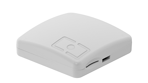
OEM
GNSS receiver
With embedded 9-DOF IMU
Photo: Rokubun
The Argonaut GNSS receiver is able to provide geo-location with real-time accuracy of 2 meters and off-line accuracy better than 0.4 meters using Argonaut PaaS. This is possible because GNSS raw measurements, together with inertial measurement unit (IMU) nine-degrees-of-freedom (9-DOF) measurements, are stored for offline GNSS processing (PPK, RTK, DGNSS). Argonaut will also register external events such as camera triggers within microsecond resolution and decimetric geo-location accuracy. The embedded IMU allows for an increased rate of navigation fixes as well as robust solutions in scenarios with impaired GNSS availability. Rokubun, rokubun.cat
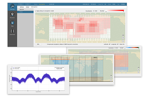
Galileo AltBOC addition
Plus atmospheric corrections
Photo: Skydel Solutions
SDX GNSS simulator update version 19.1 adds Galileo AltBOC signal generation, new atmospheric errors, SBAS improvements and SV antenna patterns. SDX users licensed with the Galileo E5 signal will be able to generate 8 Phase Shift Keying (8-PSK) constant envelope AltBOC after upgrading to SDX 19.1. Version 19.1 also adds a new error type to all SDX users: atmospheric delays. These errors can be compensated for with the SBAS option installed. Skydel Solutions, skydelsolutions.com
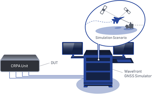
Wavefront simulator
Added to software-defined platform
Photo: Skydel Solutions
The BroadSim Wavefront Simulator is a new addition to Skydel’s software-defined platform. The BroadSim Wavefront further extends the capabilities achieved by BroadSim Anechoic, incorporating support for controlled radiation pattern antenna (CRPA) and multi-element receiver testing. Powered by Skydel SDX, the simulator’s features include phase-coherent simulation, real-time automated phase calibration, scalability from 4 to 16 elements, and advanced jamming and spoofing scenarios. Talen-X, www.talen-x.com
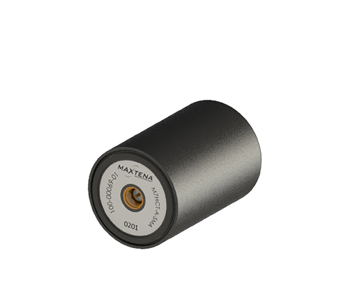
GNSS antenna
For high-precision and autonomous applications
Photo: Maxtena
The M7HCT-A-SMA is a high-accuracy, multi-frequency active quadrifilar helix GNSS antenna designed for high-precision and autonomous multi-frequency applications. The design offers concurrent GNSS reception on L1 (GPS, GLONASS, Galileo, Beidou) and L2 (GPS L2C, Galileo E5B and GLONASS L3OC) in a rugged, compact and ultra lightweight form factor. The antenna is designed for GIS, RTK and other high-accuracy GNSS applications such as the drone and automotive markets. Helicore technology provides exceptional pattern control, polarization purity and high efficiency in a 25-gram form factor. The antenna offers up to 30-dB gain for GNSS applications in one radome housing with a single SMA connector. Maxtena, maxtena.com
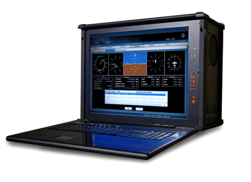
Portable simulation
Solution for field-test requirements
Photo: CAST Navigation
The CAST-1000 duplicates GPS RF signals and uses dual-frequency signal generation technology. This allows for duplicate testing in the laboratory or the field and real-time or configured control. The CAST-1000 is mobile and portable, which makes it the ideal solution for field test requirements. Producing GPS and GLONASS signals with up to 12 satellites in view, the CAST-1000 simulates signals for satellites of P code on L1 and L2 and C/A code on L1. The GPS RF signal is dual-frequency and has a 12-channel configuration for any combination of visible space vehicles. The system is highly programmable — operators can choose from an array of vehicle types and replicate dynamic motion for all kinds of vehicles, from terrestrial to aquatic, airborne to space-based. By utilizing 6-DOF dynamic profile data collected in the field and through profile configuration, a trajectory can be created. The CAST-1000 also features a performance evaluation module, allowing for comparisons between raw and filtered data. CAST Navigation, www.castnav.com
Survey & Mapping
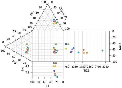
Graphing software
New plotting features
Photo: Golden Software
Version 14 of the Grapher scientific graphing package offers new plotting and customizing functionality based on user feedback. The Grapher software gives users deeper insights into their data by providing them with 80 flexible and easy-to-use 2D and 3D graphing tools for plotting, analyzing and displaying scientific data sets. The package is used extensively by scientists and engineers in oil & gas operations, hydrologic/geochemical studies, environmental consulting, mineral exploration and academic research. New or upgraded features include Enhanced Plotting (the ability to plot data in rows and columns, perform one-button Durov class plots, and easily generate multi-plot reports); and Improved Bar Charts (bar charts are more versatile, offering variable bar widths and differentiated fill colors for negative and positive). Golden Software, www.goldensoftware.com
GIS software update
New lidar functionality
Photo: Blue Marble Geographics
Global Mapper version 20.1 offers new and updated geospatial tools, as well as performance improvements throughout the application. Enhancements to version 20.1 include a new zooming function in the path profile window, a digitizer tool for automatically closing gaps between features and, for lidar module users, a point proximity query function. Blue Marble Geographics, www.bluemarblegeo.com
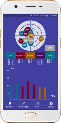
Survey application
For the geospatial industry
Photo: Global GNSS
The GNSS Surveyor mobile application provides location information and quality position data in real time with sub-meter to centimeter accuracy. It connects to any external GNSS receiver via Bluetooth. Features include a one-touch configured command to communicate directly with the GNSS Bluetooth device; location information and quality of the position data in real time with centimeter accuracy; GPS data such as position, height, satellites and velocity; and constellation information for GPS, GLONASS, Galileo, BeiDou, QZSS and SBAS satellites. It also includes a direct IP feature for real-time kinematic (RTK) corrections data. An internal NTRIP client loads RTCM data from the internet. Location information is collected as latitude and longitude, altitude, speed or pace, bearing and UTC time. GNSS precision includes global coverage, centimeter-level accuracy, fast time to first fix, multi-constellation and multi-band, and highest security. Navigation uses include ground robotics navigation, lane-level navigation, heavy machine navigation, industrial navigation and tracking, and commercial UAV. Global GNSS, globalgnss.com
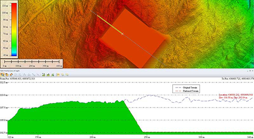
Indoor mapping
Slam technology removes point cloud artifacts
Photo: NavVis
The SLAM-based NavVis M6 Indoor Mobile Mapping System (IMMS) now automatically detects and removes point cloud artifacts, including moving objects in static scenes. The latest IMMS release removes artifacts from point clouds during the post-processing of scan data (see before and after image above). Fringe points and dynamic objects are two common types of point cloud artifacts that affect all 3D laser scanning devices. The NavVis M6 IMMS uses laser scanners to capture a high volume of measurement points of an environment. With the latest software update, the algorithms applied during the post-processing of scan data uses the multiple observations to detect whether measurement points actually exist in the physical space. If it is determined that the point does not exist and is instead resulting from the laser beam hitting an edge or an object moving through the space, this point is automatically removed. The result is a much cleaner, crisper point cloud that requires less clean-up time in point-cloud editing software and that is easier to use for applications such as BIM modeling. NavVis, www.navvis.com
Mobile & UAV
Adventure handhelds
Larger display, improved access to Satellite imagery
Photo: Garmin
Garmin has updated two premium adventure-oriented handhelds, the GPSMAP 66s and the GPSMAP 66st, with expanded wireless connectivity, direct-to-device access to BirdsEye satellite imagery, weather forecasting and a larger 3-inch sunlight-readable color display. The GPSMAP 66st offers preloaded topographic maps for U.S. and Canada, with detail of coastlines, rivers, summits, terrain contours and geographical points. Connectivity to the new Garmin Explore app and the BirdsEye Satellite Imagery (no annual subscription) bring high-resolution photo-realistic route views. Weather updates come via Bluetooth to a compatible mobile device. The Explore app includes features for outdoor navigation, trip planning, mapping and data sharing. Features include multi-GNSS satellite support and altimeter, barometer and compass sensor capabilities; 16 hours of battery life in full GPS mode; LED flashlight and SOS beacon; built to military standards for thermal, shock and water performance (MIL-STD-810G); RINEX data logging that enables sub-meter accuracy of GPS position after post processing. Garmin, garmin.com
RTK Hexacopter
Integrated GNSS improves accuracy
Photo: Yuneec International
The H520 hexacopter is now available with a real-time kinematic (RTK) system. The fully integrated RTK satellite navigation enables extremely accurate recurring images and faster 3D mapping. It also makes automated inspection flights easier and more precise. The H520 RTK is suitable for commercial applications that require maximum precision. By using RTK technology, the H520 can now fly much closer to objects for inspection because the UAV positions itself precisely in the centimeter range (1 cm + ppm horizontal / 1.5 cm + ppm vertical) rather than in the meter range, which is standard for the H520. Yuneec International, us.yuneec.com
Web-based data service
Enables sharing of UAV data sets
MAGNET Collage Web is a web-based service enabling the sharing and collaboration of UAV and scanning data sets. Version 1.3 allows operators to work with more types of data with greater flexibility, including the ability to import BIM models, as well as CAD and GIS data. It can be used to overlay as-built laser scans and design data to visualize proposed changes and detect construction issues. The software supports OBJ, FBX and 3DS formats. The upgrade also includes new direct publishing functionality for CAD and GIS data files through the browser. Topcon, topconpositioning.com
Acquisition Expands Orolia’s Global Footprint into Canada.
Orolia has acquired Skydel Solutions, a GPS/GNSS signal simulation company based in Montreal, Canada.
Orolia made the announcement at the Association of the U.S. Army’s Global Force Exhibition in Huntsville, Alabama.
Orolia is a resilient positioning, navigation and timing (PNT) solutions company and a partner of U.S., NATO and allied forces. The company provides end-to-end resilient PNT solutions, including scalable, modular and cost-effective technology to support PNT-reliant and critical defense and commercial applications.
Skydel’s capabilities allows Orolia to offer customers more diverse resilient PNT solutions with sophisticated testing and simulation protocols, additional customized signals, and superior vulnerability assessments for military and commercial applications where GNSS failure is not an option.
According to Orolia, as the latest addition to the Orolia portfolio, Skydel brand solutions bring a new paradigm to the GNSS simulator scene by combining innovative algorithms and off-the-shelf hardware to help protect the world’s most critical GNSS-reliant systems operating through GPS, Galileo and other GNSS.
Skydel technology also supports secure communications signals such as SAASM, M-code, PRS and other alternative signals with approved partners to provide real-world PNT vulnerability testing for critical infrastructure applications worldwide.
“The need for continuous, reliable GNSS signals is growing exponentially worldwide, particularly for military and commercial systems that depend on accurate PNT data,” said Orolia CEO Jean-Yves Courtois. “The threats to these systems are growing too, whether it’s through signal jamming, spoofing or meaconing. With Skydel’s unique industry expertise, Orolia now offers even more rigorous, broad spectrum testing and simulation solutions to ensure continuous signals, even in GNSS-denied environments.”
By combining graphics processing unit (GPU) accelerated computing and software-defined radios (SDR), Skydel-powered simulation solutions generate signals in real time, with uncompromising performance for demanding use cases. They are available as complete turnkey systems suitable for all GNSS simulation needs, including everything from compact test benches to complete CRPA test systems.
“Since our inception in 2014, Skydel has enjoyed exponential growth,” said Stéphane Hamel, CEO of Skydel. “This strategic move with Orolia will allow us to keep our focus on disruptive innovation and accelerate our global reach.”
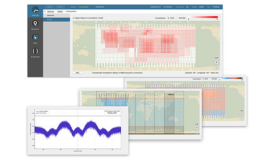
Above: A montage of screenshots showing the various updates, from a February 2019 story about Skydel updating its SDX GNSS simulator to version 19.1 with Galileo Alt-BOC and more. (Image: Skydel)
“Prepare for Tomorrow: Find Vulnerabilities Today” was the title of our wide-ranging webinar in July that focused on GNSS signal simulation for jamming and spoofing scenarios. We did not have time to address all the questions posed by the audience, so we return to them here.
Q: While testing receivers, realistic scenarios for jamming and spoofing are very important. What is the typical approach to set the number of interference sources, their type and main signal parameters?
Two different approaches are common, those involving the use of an anechoic chamber and those which are lab-based. Each approach has its limitations and merits. Each approach must address the number of significant interferers, their signal powers and the waveforms of the interference signals. Each must also consider the geometric arrangement of these interferers relative to the antenna under test and relative to the simulated constellations under test.
Changes in signal phase, signal Doppler and signal power are as important for the interference signals as they for the wanted GNSS signals. These changes are caused by the simulated motion of the vehicle and potentially the motion of the interferers. These changes should also include the impact of terrain surrounding the vehicle and the interferers, and also the gain and phase patterns of the receive antenna on the vehicle and the transmit antennas on the interferers. Some interferers might be discounted from the significant set due to their signals being masked from the vehicle by the terrain or antenna patterns or by them being too far from the vehicle to have an impact. These interference signals may become significant as the scenario progresses due to vehicle or interferer motion.
Simulator graphical user interface. (Image: Spirent Federal Systems)
Q: In GNSS navigation systems for commercial applications, what emphasis of design effort should be on anti-jamming/anti-spoofing over improving the navigation accuracy?
Commercial applications is a broad area, so it will depend on the particular application as to whether it needs more accuracy or more resiliency against AJ/AS, but in general, the accuracy of GNSS is fairly mature. Standard GNSS offers accuracies on the order of ~1 meter. Centimeter accuracy can be achieved with differential or real-time kinematic (RTK). Multi-constellation use can increase availability in areas with limited sky view such as urban canyons. Multi-frequency can aid in the reduction of multipath and improve accuracy. If the application needs accuracy, these features are readily available.
However, integrity and resiliency are growing needs in commercial applications, especially ones that are in critical operations. Much more can be done to detect jamming and spoofing than what is in standards GNSS receivers today. In our systems, we include an additional software layer called BroadShield, which monitors internal state variables of the receiver, and will alarm on detection. Additional sensors combined with the GNSS receiver such as an inertial measurement unit (IMU), magnetometer, odometer, or even the much stronger Satellite Time and Location (STL) signal offer augmentation during periods of GNSS denial, or in the case of spoofing, authentication of the navigation solution.
While both jamming and spoofing are intentional attacks, they are highly different in their set-up and serve very different purposes. Due to their simplicity, most jamming attacks can be mitigated thanks to adaptive filtering or pulse blanking. On the other hand, spoofing is a malicious attack, highly complicated, and requires knowledge of the GNSS signal structure as well as precise timing and positioning.
The question is thus whether one should emphasize navigation accuracy over the ability to output a position (jamming case) or the possibility to output a completely erroneous position (spoofing case). The answer lies, obviously, in the end application and the coupling of GNSS receivers with other systems. High-precision non-life-critical applications should emphasize navigation accuracy while implementing simple jammer filtering strategies. Life-critical applications, being often coupled with other systems, should ensure the reliability of the solution even if that means being unable to compute a position due potential threats.
Q: Do you have GPS/inertial navigation system (INS) test capabilities?
The CAST-3000 EGI integration system produces GPS RF signals commensurate with simulated IMU sensor data to provide repeatable testing in the integration laboratory for a wide range of military and government applications.
CAST GNSS/INS simulators generate high-fidelity signals required for emulating the legacy GPS signals as well as those used by next-generation navigation technologies. This is because our sole business focus is supplying GNSS simulators, GNSS/INS test equipment, and GNSS/INS support services to government and military avionics laboratories, prime contractors, and GNSS receiver manufacturers. For 35 years we have provided off-the-shelf products to both the government and U.S. major defense contractors.
CAST EGI integration tools are used by Northrop Grumman and Honeywell and are now also being used in integration laboratories worldwide. Our equipment supports system integration in major weapons platform labs and development at major military contractor labs. CAST simulators produce high-quality, accurate signals that are used in government, military and commercial labs around the globe.
Our NCS TITAN GNSS simulator is able to emulate the presence of IMUs and micro electro-mechanical systems (MEMS) sensors with the optional available real-time IMU/Sensor Emulation Package (SEP). The SEP upgrades the TITAN to support the simulation of inertial sensors, which nowadays are implemented as MEMS, among others, and of other common aiding sensors. To obtain more accurate positioning for location-based services and navigation, GNSS chipset and receiver manufacturers as well as system integrators combine more and more GNSS navigation with such sensor fusion or signals of opportunity.
The optional SEP enables controlled and progressive testing of sensor-fusion algorithms when used with NCS Control Center operating software. This software supplies the SEP with an internally- or externally-generated center-of-gravity (CoG) trajectory for the device under test.
The various sensor models to be emulated by the SEP run within the Control Center software. The device under test (vehicle) input trajectory at the CoG passes through the sensor model, which in turn generates the appropriate sensor output, by taking into account the corresponding error model for each sensor defined.
We have added the capability to emulate INS/IMU data in addition to GNSS signals to our Constellator simulator, to offer to the customers a complete testing platform. Constellator can simulate up to six gyrometers and six accelerometers. The attitude of each sensor is defined with respect to the vehicle axes. Deterministic errors can be configured to simulate the axis misalignment and scale factors, and biases can be defined in order to simulate realistic sensors. Stochastic error models are also available such as random walk or Gauss-Markov models for each sensor (gyrometer or accelerometer) to improve the sensor emulation fidelity.
Q: Do you have detailed scenarios for jamming and spoofing in timing use of GNSS receivers, that is, involving time synchronization for telecommunications companies?
The simulated jammer’s signal specification must be very flexible in order to faithfully simulate real-world jamming events. For example, the jammer’s spectral shape should be flexible enough to simulate a Blue Force electronic attack (BFEA) on a GNSS receiver.
Also, the simulator should be able to simulate dynamic scenarios by varying the power of the jammers as a function of their trajectories and as a function of different antenna patterns.
Sometimes when testing receivers, the simulated jammers should replicate pre-recorded waveforms from real world. The ability to play back the pre-recorded IQ-baseband signal in conjunction with GNSS signals is another powerful feature of a simulator. Simulation of spoofing attacks on a GNSS timing receiver is only possible when the GNSS simulator provides fine-grained control of transmitted signal. This includes controlling the offsets on the pseudoranges with additive ramps, as well as individual signal power levels at very precise points in time.
Also, the GNSS simulator must be able to synchronize itself with the live sky’s GNSS signal. Another way to achieve realistic spoofing is to use two simulators controlled independently (that is, full control on constellation, navigation message, propagation time offset, power and so on).
FIGURE 1. Real-world jamming simulation must take into account key factors such as varying jammer power, as a function of their trajectories and antenna patterns. (Image: Skydel)
Q: Please discuss how to simulate a smart spoofer that would generate a replica of a constellation (or all constellations) and then produces two full RF transissions: one that is the true signal, and a strong spoofed signal that pulls the receiver to a false location. Can you simulate the two full multi-band RF ensemble?
Two artificial synchronized scenarios could be created using SatGen signal generator software that can reproduce the GNSS signals from a number of constellations. The user could create two separate signal streams, both starting at exactly the same position and time and using the same constellations, chosen by the user.
The second scenario could then be set to diverge away in position from the first scenario, while staying perfectly synchronized in time. The signal-to-noise ratio of each scenario could be adjusted independently of each other to simulate a spoofing situation where the spoofing signal is much stronger than the real signal. A file containing this twin scenario can be replayed using a LabSat Wideband with two separate RF outputs, each synchronously replaying the two different scenarios. This would closely simulate the actions of a smart spoofer, but in a completely repeatable, and controllable manner.
This could be accomplished by either combining the output of two of our CLAW GPS simulators, or by combining the output of a single CLAW simulator with live-sky signals using passive industry-standard splitters/combiners. The CLAW is able to receive a custom ephemeris download in RINEX format to match either the spoofed live-sky constellation, or to generate a synthesized constellation in the case where two CLAW simulators are being used.
The simulator has a wide RF power adjustment range of over 45-dB, allowing the spoofing signal to be gradually introduced to the primary GPS constellation RF signal. This spoofing simulation could be accomplished with better than 0.5 meter peak-to-peak positioning accuracy and better than 5-ns real-mean-squared (rms) typical UTC (GPS) offset unit-to-unit, allowing the victim receiver to be pulled off of its true (live-sky) position with very high accuracy. Typically, GPS receivers are spoofed easily as long as the UTC timing synchronization is 500-ns or better between the live-sky and spoofed signals.
Timing synchronization to the spoofed victim GPS signal to within nanoseconds is achievable through the external 1PPS reference input, the simulator accepting a position, navigation and timing (PNT) fix in real time via its NMEA serial and 1PPS inputs. This allows capturing a moving victim receiver by estimating its momentary position, then ramping up the spoofer power, and then presenting the victim receiver with alternate position information as required (see Figures 2 and 3).
High position and timing accuracy between the spoofed and live-sky signal is important to prevent and mitigate spoofing detection via UTC phase or position jumps that could happen when the receiver gradually or quickly switches over to the spoofed satellite signals.
FIGURE 2. Spoofing attack on a GPS receiver using a CLAW simulator to spoof a live-sky antenna signal. Initially the spoofer was phase- and frequency-synchronized to UTC(GPS), then spoofer RF power is ramped up, and once the victim GPS receiver is captured, a frequency offset is added to UTC(Spoofer), which pulls the system off-phase. (Figure: Jackson Labs)FIGURE 3. Simulating a spoofing attack on a timing application where the spoofer does not know the exact victim antenna location with certainty. The resulting antenna position offset error (50 meters in this simulation) still allows the victim receiver to be captured, and then causes a time error as satellites move in and out of view even with the spoofer being synchronized to UTC(GPS) at all times. This error is clearly visible in the resulting UTC(Spoofer) output from the victim receiver equipment. (Figure: Jackson Labs)
Q: We want to correctly model and simulate effectiveness of various anti-jamming (AJ) and anti-spoofing (AS) solutions to make informed decisions about which AJ/AS solution is most effective for a specific mission and interference scenario. How can you help?
Live-sky testing on a jamming/spoofing range provides a wealth of data, and reassurance that the system under test does work as intended. Record and playback systems (RPS) under live-sky conditions can allow further evaluation back in the lab, after the live-sky tests are complete. Performance parameters of the RPS may degrade the validity of the signal when played back; signal bandwidth and bit-depth are absolutely key, for example. Recordings that use too few bits will degrade the dynamic range of the recorded signals, so significant care should be taken when selecting an RPS.
Either way, under live-sky or with recorded live-sky, you get what you get. It is extremely difficult to predict what the test parameters actually are. It is perilous to attempt to alter the test parameters after the event. Lab-based or anechoic chamber-based systems have their limitations, but they are repeatable, predictable and tweakable. Again, performance parameters of the simulation system play a key role in the validity of the testing. The ability to calibrate the simulation system to give a repeatable, predictable performance is as important as the realism of the simulation. Carrier-phase accuracy/repeatability among antenna elements and signal timing accuracy are important parameters when evaluating AJ and AS systems.
Q: We had a receiver where the time stamp for any location report would drift off progressively, up to an hour off of the known true location. What might contribute to this? We do not believe this was an intentional threat, but an artifact of nearby electronics or other system conditions. It actually occurred on a pivot irrigation arm in motion, with substantial vibration. The receiver was electrically isolated. The results were repeatable on the pivot arm, but not on our vibration table.
Interesting problem with no obvious answer. Even the worst oscillator will take many months to drift off by up to an hour with no GNSS, even under horrible vibration conditions, so this is an unlikely cause. Is it drift or a jump in error? Nearby electrical noise could cause GNSS denial (jamming), but not erroneous data. That requires spoofing. If you have no reason to believe that it is intentional, that makes spoofing unlikely, but still possible. Is a GNSS repeater or a record/playback GNSS tester operating in the area? These are spoofers, even if they are unintentional.
If this is a precision agriculture application, then an RTK reference station transmitting erroneous data could be the cause. What time-stamping format is used: local time or UTC? An unlikely but possible scenario is the unit is changing time zones so local time jumps an hour. Is there a processor/software app between your output and the actual GNSS receiver? This could introduce errors. What is the position output indicated when the time drift occurs? The best way to diagnose this is to record the time and position output as log files using a laptop PC connected to the serial data.
Q: Do your simulators work as well for testing handheld, consumer-grade GPS? Please discuss the differences in testing techniques or approaches for high-precision vs. mass-market receivers?
We have a range of simulators suitable for all levels of GNSS testing. If you don’t need the high fidelity and wide bandwidth of the LabSat Wideband, then the entry level LabSat 3 will also work with any GNSS device including handheld consumer-grade products.
To fully explore the performance of high-precision receivers, including multipath effects and P-code reception, a wider bandwidth and a greater number of bits would be required to capture and replay all of the available signals. For these applications, we recommend a bandwidth of 56 MHz and at least 4 bits of resolution.
For testing of consumer-grade, handheld devices with simpler RF front ends, we recommend a much reduced bandwidth of around 9 MHz and only 2 bits of resolution. This smaller bandwidth and fidelity will easily reproduce the majority of real-world conditions, and the resulting data files will be much easier to handle.
FIGURE 4. Simulator graphical user interface. (Image: Racelogic)
Q: How many GNSS signals can a software-defined radio produce?
The theoretical limits of a software-defined radio (SDR) are based on four distinct characteristics of the SDR: the digital-to-analog converter’s (DAC’s) bit resolution, the maximum sampling rate, the bandwidth and the number of RF outputs. With most SDRs, available bandwidth is defined by the sampling rate.
With a 16-bit DAC, there is enough dynamic range to generate up to 50 GNSS signals and hundreds of multipath echos (with more than 60 dB of range to accommodate different signal power levels) per RF output.
For example, with a sampling rate of 50 MSps, a 40-MHz wide signal — combining GNSS constellation signals such as GPS L1 C/A, Galileo E1, GLONASS G1 — can be generated. Nowadays, SDRs can have two or more RF outputs and are able to operate with sample rates of 100 MSps or higher. By distributing the GNSS signals across different RF outputs, the entire GNSS spectrum can be covered at a relatively low cost in terms of hardware.
A handful of SDRs can easily be synchronized to form multiple RF output systems. In such cases, the complete range of GNSS signals for all visible satellites can be generated at the same time.
Q: In a dual-frequency receiver would it be possible to still use L1 spoofed/jammed with L2 clean to get an accurate position? Is it possible to do a combination between the two signals in order to save the spoofed/jammed L1?
In principal, it is still possible to use L1 spoofed/jammed with L2 clean in a dual-frequency receiver to get an accurate position. Such receivers are available as off-the-shelf products. These receivers use a special algorithm to detect if a GNSS frequency band is spoofed/jammed and automatically switch over to the clean frequency band. However, this principle can only be applied if the entire GNSS spectrum is not completely jammed. Whether a dual-frequency receiver can still use L1 spoofed/jammed with L2 clean to get an accurate position is therefore finally basically dependent on the overall bandwidth of the interferer/jammer.
With IFEN’s TITAN simulator, it is possible to easily create the corresponding simulation scenarios for the real-time simulation of realistic test scenarios to test the robustness of GNSS receivers against interference/jamming and also spoofing. In doing so, various static and dynamic interference/jamming sources are supported by the simulator’s software.
It is possible to achieve a PNT solution using L2 signals only. This requires reception and decoding of either the military L2 P(Y) signal, or reception of the new but still pre-operational L2C commercial signal. Codeless or semi-codeless commercial L1/L2 receivers rely on tracking the carrier phase on L2 to be able to mitigate effects such as solar flares and ionospheric errors; however, they are not capable of generating a PNT solution with L2-only reception as would be the case under this spoofing/jamming scenario.
P(Y) signal reception on L2 typically requires reception of the coarse acquisition (C/A) signal on L1 prior to tracking P(Y) unless the receiver has its own internal (atomic) time-base synchronized to UTC to the sub-microsecond level.
On-Demand Webinars
Simulation against Jamming and Spoofing: With cyber attacks on the rise, it is more critical now than ever to thoroughly test GPS and GNSS systems against jamming and spoofing.
Skydel Solutions has released SDX Release 17.8, which offers a host of improvements, according to the company. The 17.8 release offers an advanced jamming feature, as well as improvements for Gaussian noise, spectrum view and the graphical user interface (GUI).
The new advanced jamming option provides unique interference testing capabilities for SDX users. It leverages the power of the GPU/SDR combo to create a new way to simulate interferences, enabling transmitter trajectories and user-defined waveform creation.
Skydel Solutions will be exhibiting at ION GNSS+ in Portland, Oregon, in booth #100. Attendees can learn about the new system and watch a demonstration of SDX’s latest features. Also, Skydel’s Iurie Ilie will host a technical session about spoofing on Friday, Sept. 29, at the conference.
With SDX’s Advanced Jamming package, users can:
Create user-defined waveforms. Chirp, CW, BOC, AWGN, BPSK and pulse interference modulation are supported and can be combined at will to create custom, complex interference waveforms.
Create multiple real-time jammers. Users can create a single or multiple jammer transmitters with user-defined waveforms. Up to 100 interferences can be generated in real time.
Add dynamics to transmitters. Users can create more realistic jammers for simulations; SDX’s dynamic jammers can change position relative to the receiver as the simulation progresses. Their power levels are defined from the transmitter’s point of view. During the simulation, SDX automatically calculates the resulting signal at the receiver antenna in real-time and takes into account the transmitter antenna pattern, the propagation loss and the receiver antenna pattern. The transmitter, like the simulated receiver, has six degrees of freedom. Furthermore, the trajectory may even be defined in real-time using the hardware-in-the-loop API.
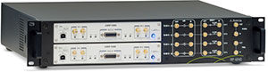
Talen-X has been given security approval by the GPS Directorate, allowing BroadSim to create and process Y-Code while in a classified environment.
BroadSim is a software-defined GNSS simulator that enables users to easily model true and spoofed signals. BroadSim was developed to simplify advanced jamming and spoofing scenarios with Navigation Warfare (NAVWAR) testing in mind.
BroadSim supports high dynamics, advanced jamming, spoofing and encrypted military codes.
Powered by Skydel’s SDX 1000-Hz software simulator engine, BroadSim can simulate multiple constellations including GPS, GLONASS, Galileo and BeiDou.
Software features:
Capable of generating and simulating multiple signal types
GPS L1, L2 with C/A, P, Y and M
GLONASS G1 and G2
Galileo E1 and E5
BeiDou B1 and B2
Intuitive control using Skydel’s SDX software
Utilizes four RF outputs, each with multiple simultaneous constellations
Generates high-fidelity jamming and interference signals
BroadSim hardware includes a generator and controller with two integrated commercial-off-the-shelf USRP radios, an integrated OctoClock-G with GPS disciplined oscillator, four frequency-independent transmit and receive channels and a UBX-160 RF daughterboard.
A: Spoofing is normally associated with the creation of false signals in order to generate a position error, but the same technique may be used to distort a timing solution. With GNSS timing systems being used in critical infrastructure, like power supply, financial transactions and data network synchronization, disruption of timing solutions could have catastrophic implications. GNSS simulators can be used to test the vulnerability of current timing systems and also the effectiveness of potential mitigation techniques.
A: An expanded set of tests for anomalous conditions. The growing number of GNSS signals offers attractive performance benefits, but also multiplies exposure to GNSS errors and interference. Functional requirements are clear to the developer and are naturally developed first. Defining response to anomalies is a less clear task, which too easily becomes a secondary concern. To ensure coverage of the larger test space, multi-GNSS development now requires that anomalous cases be addressed earlier, at priority on par with core functional requirements.
A: Multi-Constellation performance. Using two or more constellations can significantly increase coverage under adverse, limited-sky-view situations. Using two or more frequency bands will combat interference and jamming, and deriving a PNT solution from multiple constellations is a great way to detect spoofing. Integrators/ developers should be using a simulator to verify how the system/receiver behaves under loss of sky view, jamming or spoofing when tracking any combination of multiple constellations.
A: The recent explosion of wearable technology has led to a proliferation of devices being used in “edge-case” situations, with receiver performance being put under greater pressure to perform in a multitude of potential scenarios. A record and replay simulator gives you real signals as opposed to modeled ones, allowing for GNSS product development to be conducted with absolute realism, resulting in greater robustness within the market.
A: The threat of intentional broadcasting of a fake GNSS signal is dangerously growing. GPS spoofing is real and not a military-only concern. The proliferation of SDR and open-source code make spoofing accessible to malicious people even without extensive knowledge in the field of GNSS. Most GPS receivers, as tests show, are vulnerable to spoofing, and no warnings are generated when it happens. Test engineers should definitely consider spoofing attack detection in their test plans.
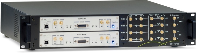
Averna and Skydel Solutions will be showcasing their latest GNSS technology simulation products at The Institute of Navigation (ION) GNSS+ conference, giving show-goers the opportunity to see the RP-6100 in action.
ION GNSS+, taking place Sept. 14-18 in Tampa, Fla., is the 28th International Technical Meeting of the Institute of Navigation’s Satellite Division and the world’s largest technical meeting and showcase of GNSS and related technology, products and services.
The companies will be presenting at Booth #100 in the Exhibit Hall, meeting attendees and discussing their latest innovations in GNSS receiver validation, among other topics. They will also be demonstrating two new GNSS solutions:
RP-6100 Multi-Channel RF Record & Playback: The RP-100 for RF application testing allows users to tecord real-world signals such as GNSS, HD Radio, LTE and Wi-Fi — plus impairments — to significantly advance projects and harden product designs.
GNSS Simulator: New from Averna’s partner Skydel Solutions, this innovative and cost-effective simulator is entirely software driven. It’s a perfect fit with the RP-6100, Averna said, enabling users to test corner cases and future events with a real-time GNSS solution.
Averna RP-6100 record and playback solution. (PRNewsFoto/Averna)