Tag: software-defined radio

  • Innovation: Software-defined radios for GNSS

    Innovation: Software-defined radios for GNSS

    A Step-by-Step Exposition of an Educational Resource

    Innovation Insights with Richard Langley
    Innovation Insights with Richard Langley

    THE RADIO. It’s been around for more than 100 years. Pioneering work by Guglielmo Marconi and others in the1890s and 1900s resulted in practical wireless telegraphy devices that permitted point-to-point communications with ships at sea and between stations on land hundreds and thousands of kilometers apart and even between stations on different continents. The first radio broadcasts (point-to-multipoint) were time signal transmissions and weather broadcasts. Experimental audio transmissions took place in the early 1900s, and by 1920 or so, radio stations were established in many countries for broadcasting speech and music to the general public.

    The first radio receivers were simple crystal sets. It wasn’t until the mid-1920s that tube radios became commercially available. Eventually, tubes were replaced by transistors, and transistors by integrated circuits. The introduction of microprocessors resulted in digital receivers, with the conversion of the received analog radio signals into audio being carried out digitally for the most part.
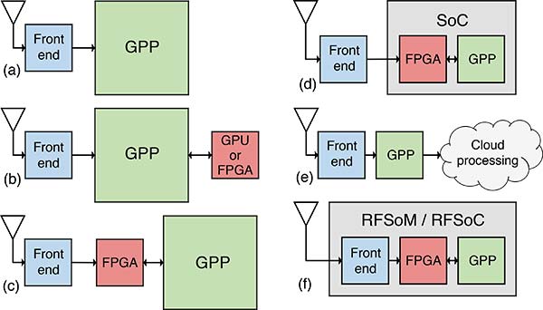
    One of the latest advances in radio technology is the software-defined radio or SDR. An SDR typically consists of two components: a piece of hardware, called a radio frequency (RF) front end, and a piece of software run on a general-purpose computer. The job of the front end is to convert a portion of the radio spectrum received by its antenna to a digital data stream processed by the software. The software decodes the data to produce the desired result. Since the software does most of the “heavy lifting” in processing a radio signal, it is often called the SDR itself. And by the way, there are SDR transmitters, too.

    It should come as no surprise that SDR technology has come to the GNSS field. In fact, in 2007, the seminal text on GNSS SDRs, A Software-Defined GPS and Galileo Receiver: A Single-Frequency Approach, was published along with the sale of an inexpensive RF front-end in a thumb-drive-sized package that allowed graduate students and others to experiment with a GNSS SDR themselves. And we have covered GNSS SDR developments in this column from time to time, most recently in January 2018 (“The Continued Evolution of the GNSS Software-Defined Radio: Getting Better All the Time”).

    In this month’s column, researchers from the lab that helped produce the SDRs documented in the 2007 book (which is still in print) discuss their development and testing of additional freely available SDR codebases covering all four GNSS (GPS, Galileo, BeiDou and GLONASS). They provide an excellent resource for learning how GNSS receivers actually work.


    By Joan Bernabeu, Nicolas Gault, Yafeng Li and Dennis M. Akos

    With the publication of the book A Software-Defined GPS and Galileo Receiver: A Single-Frequency Approach by Kai Borre, Dennis Akos and their fellow authors, an open-source GNSS software-defined radio (SDR) receiver developed using Mathwork’s Matlab language was made available, together with sample data sets that facilitated the testing process for all interested readers. The first SDR implementation focused on processing the GPS L1 C/A-code legacy signal and served as a starting point for students and researchers in the Radio Frequency (RF) and Satellite Navigation Laboratory at the University of Colorado Boulder, where later activities aimed to improve the software code and add new features as new GNSS signals emerged. As a result, the initial codebase evolved into a complete collection of SDRs capable of processing all GNSS signals from every satellite constellation, with BeiDou’s B1I, B1C, B3I and B2a signals the latest additions. The most recent efforts were dedicated to collecting all SDR codebases, putting them in a common format, and testing them to give an account of their performance. This article describes our efforts, placing special emphasis on explaining the test framework designed to test each SDR, as well as on reporting the adjustments made and the results obtained. GPS test cases have been taken as examples to show how some SDRs were assessed when issues were found in the results they provided.

    OPEN-SOURCE GNSS SDR COLLECTION

    The whole SDR collection has been developed in Mathwork’s Matlab programming language. To run the code and perform tests, users simply require an active Matlab license and the software available on their computer. Once these requirements are met, the user can choose to download any of the available codebases and the corresponding data set to start experimenting. 

    We recommend using version control software to keep track of changes made to the original version of the code. Users should consult the Borre et al. text for further details on running the codebases.

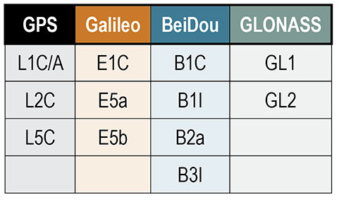
    A total of 12 SDR codebases are aimed at processing each of the GNSS signals (see TABLE 1). All code files for each SDR are organized in the same subdirectories, and most of them have the same filenames. 

    Table 1. All GNSS signals that can be processed by the SDR collection, organized by their corresponding satellite systems.
    Table 1. All GNSS signals that can be processed by the SDR collection, organized by their corresponding satellite systems.

    All SDRs are set to work with a default configuration. They are all run using an init.m script, which collects user settings (input data file path, sampling frequency and so on) from the initSettings.m configuration script. Given this, the first file that users may want to modify is initSettings.m, to define the run settings for a given test. Most of the SDRs operate in an identical way, however some include particular features oriented at exploiting certain characteristics of the corresponding GNSS signal. The GPS L2C SDR, for example, gives the user the option of whether to process the pilot component of the signal.

    The test samples available in the public directory were obtained in accordance with the characteristics depicted in TABLE 2 for every signal. The first two columns from the left show all the signals the SDR collection can process and the central carrier frequency at which they are transmitted. The third column gives the bandwidth selected in the recording process for every signal. This value must match the sampling frequency defined in the initSettings.m file for each SDR. Only three frequency bandwidths can be used to record GNSS data, so as to make the configuration structure more homogeneous across different SDRs. They were selected to ensure similar characteristics for each signal in terms of performance, encompassing most of the signal power for each modulation, but also keeping the recorded GNSS data files within a reasonable size.

    Table 2. Summary of the tested GNSS signals’ center frequencies and the selected bandwidth (BW) for their processing. The common IF for all signals is 20 MHz.
    Table 2. Summary of the tested GNSS signals’ center frequencies and the selected bandwidth (BW) for their processing. The common IF for all signals is 20 MHz.

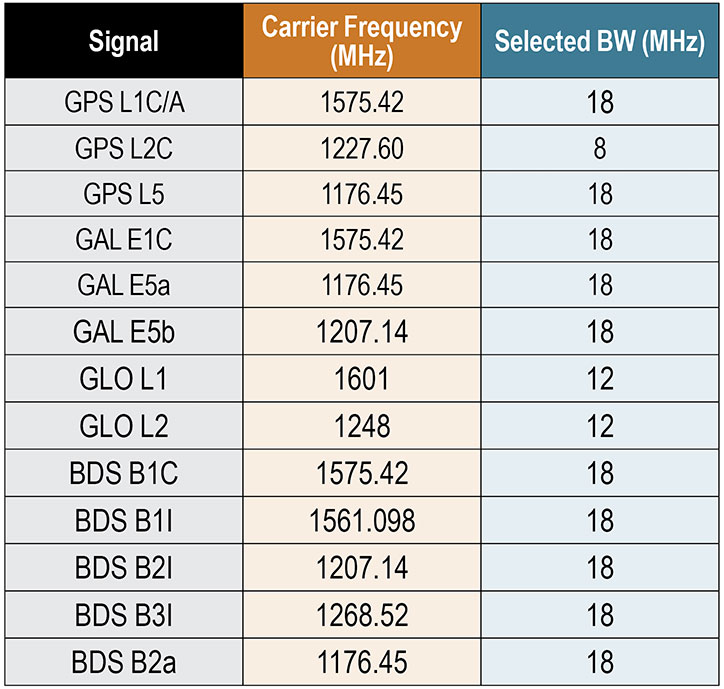
    All the signals were mixed to a common intermediate frequency (IF) of 20 MHz in the recording process. Both the frequency bandwidth and the IF are fundamental to obtain the expected results from each SDR codebase. These are set in the settings file. The default configuration was validated in the testing campaign explained in later sections, and should only be modified to meet the user’s specific needs, being aware that some SDR performance characteristics may also be affected.

    BASIC GNSS SDR STRUCTURE

    While the general SDR receiver structure is similar across all codebases, each comes with adjustments and/or additions to adapt the code to the format of a specific signal. The general codebase structure can be summarized in four major modules:

    • signal acquisition
    • tracking stage
    • navigation data decoding
    • position, velocity and time (PVT) computation.

    An important remark is that the SDR collection developed is designed to process files of limited duration. The code is designed to use enough data to provide a successful initial acquisition, and then use a single set of satellites for the remaining execution. In other words, there is no extra logic oriented at acquiring or reacquiring satellites after the first acquisition is achieved.

    Signal Acquisition. The design of the acquisition scheme depends on the characteristics of the signal the SDR is aiming to process. There are numerous GNSS signal configurations for each constellation that follow different strategies concerning spreading codes, navigation data and secondary codes, which must be accounted for in the acquisition codebase.

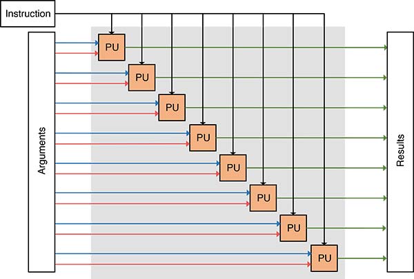
    All codebases follow a fast Fourier transform (FFT) accelerated serial search-acquisition approach to obtain estimates of the signal’s carrier frequency and code delay, where a number of signal replicas are generated iteratively, separated by a defined frequency interval in the frequency domain. All the frequency offsets are arranged in what are known as frequency bins. This frequency separation will be referred to as the frequency step. The latter is inversely proportional to the integration time and tells the maximum error allowed in the carrier frequency estimate, which is half the frequency step. Both the frequency step and the coherent integration time are parameters that have a strong effect in acquisition results, as will be seen below.

    Each local replica is correlated with the input signal to obtain a code-phase estimate. The length of this correlation is the so-called coherent integration time. The maximum correlation measurement from all frequency bins is then divided by the second maximum found. This ratio is called the peak metric and is used in all SDRs to give a measure of the magnitude difference between the maximum obtained and the remaining correlation results. If the peak metric is not high enough, this implies that the maximum is close to other cross-correlation products and so could not correspond to the result obtained after correlating both input and local replica signals with the right code-phase alignment. When the peak metric surpasses the threshold defined in initSettings.m, the satellite is considered to be acquired. 

    It is worth noting that in all SDR implementations the local replica is constructed by concatenating a whole primary code and a block of zeros of the same length. This prevents navigation bit transitions from affecting the correlation results. For example, GPS L2C-CM SDR’s acquisition correlates 40 milliseconds of data with 20 milliseconds of pseudorandom noise (PRN) spreading code followed by 20 milliseconds of zeros (the zero padding technique). 

    Tracking Stage. The tracking stage is oriented at refining and keeping track of the code and carrier estimates provided by the acquisition stage as well as demodulating the navigation data. This is achieved using feedback loops organized in channels, which are typically referred to as tracking channels. There will be as many tracking channels as the number of satellites acquired. Each tracking channel makes adjustments to the corresponding local signal replica for the given satellite, so that it resembles the real received signal as much as possible. When the replica is sufficiently accurate, the tracking loop locks onto the signal, removes the carrier and spreading code components, and starts registering data bit transitions. The task of every tracking channel is to account for signal variations so that they can keep locked on the signal for as long as the satellite is available for use.

    Tracking channels implement two feedback loops, the delay lock loop (DLL) and the Costas phase lock loop (PLL). The former is focused on the signals’ code phase while the latter on the carrier phase. These modules depend on two major parameters that determine the properties of the loop filter: the damping ratio and the noise bandwidth. On the one side, the damping ratio controls how fast the filter reaches the settling stage. On the other side, the noise bandwidth informs the amount of noise allowed in the filter.

    While all SDRs follow similar tracking loop schemes, some signals, such as GPS L2C, need some adjustments to the parameters mentioned above so that they provide the expected results, as we point out later. Tracking results are stored in a Matlab .mat file, but also can be assessed in the plot the tracking stage generates after it finishes processing all the channels.

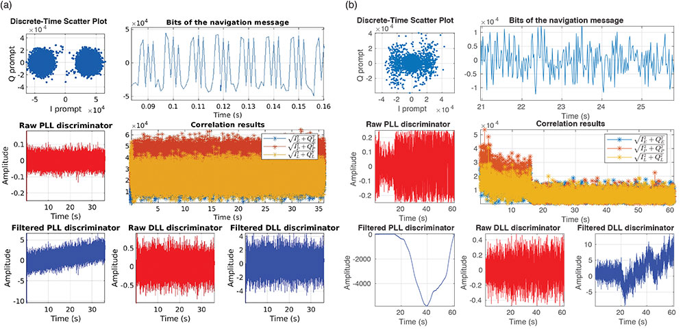
    FIGURES 1a and 1b show an example of two different tracking results plots, each of which include seven figures. These show the in-phase/quadrature (I/Q prompts), the navigation data bits decoded, the changes in the raw/filtered Costas loop and DLL discriminators, and the early-prompt-late metrics. Note that the plots in Figure 1a suggest the navigation data bits were demodulated successfully. In contrast, in Figure 1b, data bits cannot be distinguished because the tracking stage failed to demodulate the navigation message.

    Figure 1. (a) shows the plot generated for a successful tracking channel. In contrast, (b) illustrates the results obtained when the tracking loop in question did not lock appropriately to the signal and therefore was not able to demodulate navigation data. (Image: Authors)
    Figure 1. (a) shows the plot generated for a successful tracking channel. In contrast, (b) illustrates the results obtained when the tracking loop in question did not lock appropriately to the signal and therefore was not able to demodulate navigation data. (Image: Authors)

    Navigation Data Decoding. This stage extracts the navigation data required by the SDR codebase to compute PVT estimates from the results delivered by the tracking stage. The latter outputs I/Q prompt samples representing data bits, containing the encoded navigation data. The navigation data format for each signal can be found in the interface control document issued by each satellite constellation operator.

    The general process that each SDR implements to demodulate navigation data from I/Q samples is summarized as follows:

    1. detect a preamble within data bits
    2. arrange the bit sequence in the corresponding structures, such as frames
    3. remove secondary code if present
    4. de-interleave and decode
    5. check if the bit stream has errors
    6. extract navigation parameters

    Once navigation parameters are extracted, they are stored and later used by the functions involved in the PVT computation stage.

    PVT Computation. The PVT stage takes the decoded navigation data, computes satellite positions, and solves the geometry problem, whose solution is the receiver’s location.

    As with all the other stages, all SDRs follow the same approach, and use the least-squares method to solve for a position estimate once all the data is available. Position estimates are delivered in both Earth-centered Earth-fixed and east-north-up coordinates.

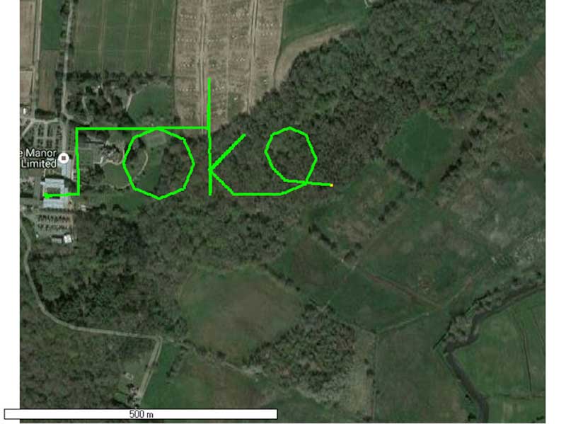
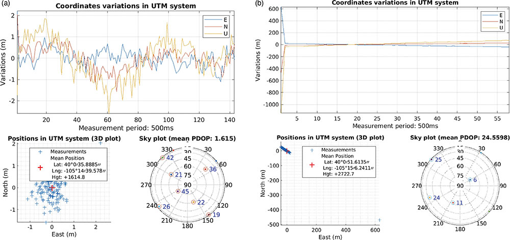
    Similarly to the tracking stage, the PVT computation stage returns a plot showing some PVT statistics to help the user get an idea of the PVT performance of the test conducted. FIGURES 2a and 2b show an example of two positioning plots obtained for two different data files. 

    Figure 2. (a) shows the plot of a priori, good statistics for the navigation solution; (b) shows a navigation plot for a file that presented a problem affecting the PVT solution. (Image: Authors)
    Figure 2. (a) shows the plot of a priori, good statistics for the navigation solution; (b) shows a navigation plot for a file that presented a problem affecting the PVT solution. (Image: Authors)

    EXPERIMENTAL SET-UP AND TESTING

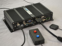
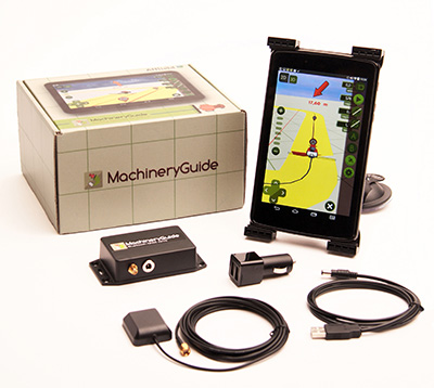
    In this section, we present the equipment we used in our tests (see FIGURE 3) and detail the process we followed to collect GNSS data, as well as the testing framework designed to exercise the SDR collection. 
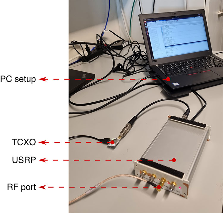
    Figure 3: The antenna was connected to the RF port of the USRP. The USRP sampled the analog data delivered by the antenna using the TCXO as the reference oscillator. The resulting sampled data was stored in a Linux-based computer. (Image: Authors)
    Figure 3: The antenna was connected to the RF port of the USRP. The USRP sampled the analog data delivered by the antenna using the TCXO as the reference oscillator. The resulting sampled data was stored in a Linux-based computer.
    (Image: Authors)

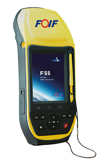
    RF Antenna. The device used to sense the RF GNSS signals was a Trimble Zephyr2 antenna, which has enhanced capabilities for multipath minimization as well as low-elevation-angle satellite tracking properties. 

    The antenna was installed on the rooftop of the Ann and H.J. Smead Department of Aerospace Engineering Sciences building at the University of Colorado Boulder.

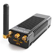
    USRP and TCXO Devices. An Ettus Universal Software Radio Peripheral (USRP) B200 hardware SDR connected to an IQD temperature-compensated crystal oscillator (TCXO) was used to collect digital samples from GNSS analogue signals sensed by the antenna.

    The B200 device was controlled by means of the USRP hardware driver (UHD) through a computer running a Linux operating system. UHD is a software application programming interface (API) that enables the development of code to manage USRP settings and operation. 

    PC Setup. The PC setup consisted of a Linux computer  with all the required drivers and program dependencies, as well as with Mathworks’ Matlab software installed. Matlab was used to program and automate the data recording process.

    Recording Process. The equipment described in previous subsections was used to record data suitable for each SDR codebase. The process to obtain signal data for all 12 codebases was reduced to eight stages by selecting an adequate frequency bandwidth, as some signals share the same central carrier frequency (see Table 2).

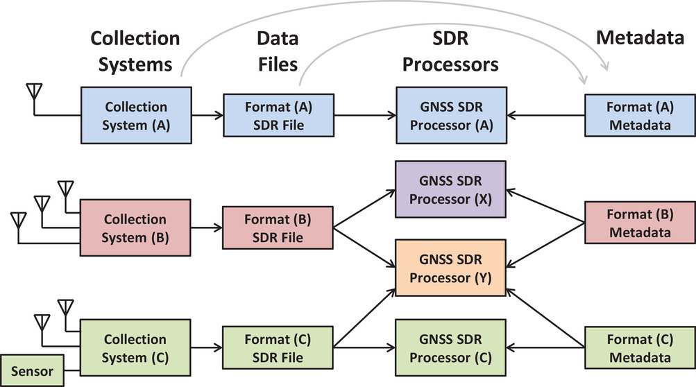
    For each stage, a total of 100 files with 61 seconds of I/Q GNSS data were recorded over a 24-hour time period. The I/Q samples recorded by the USRP were formatted as 8 bit sine carriers. All the data sets recorded are available together with a description file based on the Institute of Navigation’s metadata standard for GNSS.

    TESTING FRAMEWORK

    The workflow we followed to test every codebase from the collection is outlined in the following steps:

    1. Record data samples. A set of one hundred files were recorded with 61 seconds of GNSS data.
    2. Debug the SDR with the selected files. A debugging stage preceded every test case to ensure the codebase performed well enough, or else to make the required adjustments.
    3. Run the SDR for one hundred trials. A total of one hundred tests, one per file, were performed for all SDRs.
    4. Log metrics and present results. The results from all SDR stages (acquisition, tracking and data demodulation) were stored for each file. Also, each iteration returned a message that summarized the execution results.

    All of the messages returned for every file corresponded to one of the cases summarized as follows:

    1. Codebase issue. Message type returned when the codebase failed because of a coding issue.
    2. No navigation solution. The codebase was not able to deliver a navigation solution either due to a malfunction of the codebase or due to a lack of satellite availability. Navigation solutions are only available when both the tracking channel and the navigation data demodulation stages are successful for more than three satellites.
    3. Navigation solution with accuracy worse than 30 meters. A position solution fix more than 30 meters (in three dimensions) from the known antenna location was considered a non-accurate estimate.
    4. Navigation solution with accuracy under 30 meters. When the 3D positioning error was < 30 meters, the navigation solution for the position was considered accurate.

    All codebases passed a debugging stage before being tried with the whole set of available data. This was done to ensure that they performed as expected, and were able to achieve the required performance in terms of the metrics mentioned above in this section. An example of this debugging stage will be explained in further detail below. We take the GPS L2C codebase as an example of how all implementations were assessed in an attempt to improve their initial performance and make them more robust to code errors. See our proceedings paper for further details of our test cases.

    GPS L2C Test Case. The problem observed for GPS L2C was that some satellites acquired with a high acquisition metric were failing the tracking stage. The result was that no navigation data was demodulated from them. An in-depth study was required to find out the adjustments needed in the codebase that would help to solve this issue.

    The GPS L2C signal encompasses two signal components called civil moderate (CM) and civil long (CL). The CM component is formed by a spreading code that modulates a navigation message. The CL component is a pilot (data-less) signal modulated with a longer spreading code allowing for longer coherent and non-coherent integration times, yielding better sensitivity. 

    For CM signal acquisition, the 20 millisecond code length limits the coherent integration time to 20 milliseconds, due to the overlaid navigation message. This integration time defines the minimum frequency resolution required to obtain the expected correlation results. The CL component is used in the SDR to accumulate consecutive correlation results non-coherently, contributing to the receiver’s sensitivity by allowing it to operate with higher acquisition metrics in general.

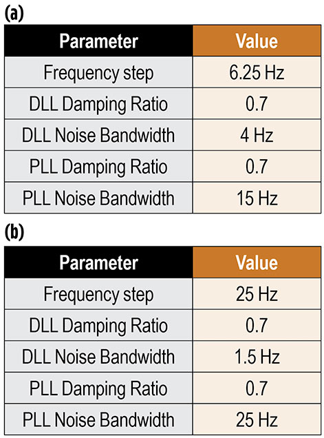
    The initial configuration for this SDR codebase is represented in TABLE 3a.

    Table 3. Configurations for GPS L2C test case.
    Table 3. Configurations for GPS L2C test case.

    With this configuration, a total of 10 satellites were acquired. However, it was observed that for some satellites acquired with high peak metrics, it was not possible to demodulate their navigation data, and thus they were not considered for the navigation solution in later stages. This situation was abnormal, as typically this behavior is more characteristic of weaker signals whose bit transitions are too noisy to be decoded. This problem suggested that either the code-phase or the carrier frequency estimates (or both) were not accurate enough for each tracking channel to generate a proper replica to lock onto the input signal.

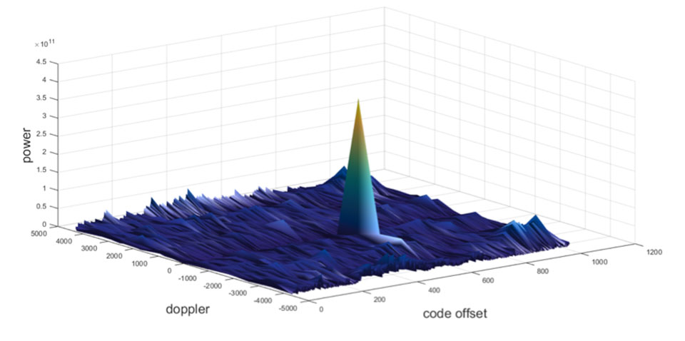
    The first step taken to address this matter was to inspect the SDR’s acquisition stage for a file presenting the mentioned problems. For instance, taking a closer look at the carrier and code-phase 3D representation for those satellites acquired with a high acquisition metric that were not successfully tracked afterwards. After doing so, some satellites were identified with the irregular characteristics described above, as for example the PRN 10 satellite. PRN 10 is taken as a reference throughout this subsection.

    The metric analyzed for PRN 10 was the matrix built by the acquisition’s serial search process. This matrix contains the correlation results obtained for each frequency bin. The width of each frequency bin is determined by the frequency step size defined in the configuration file. In this way, the smaller the frequency step, the more frequency bins that the corresponding matrix contains. This implies a better frequency resolution. 

    With this in mind, the frequency resolution was progressively increased by decreasing the frequency step size. Extra logic had to be added to the acquisition algorithm to implement this feature. It was found that when using a step size of 6.5 Hz, the tracking stage was then able to lock and demodulate navigation bits from PRN 10 effectively. This was the most significant determining factor to overcome the issue in question for the majority of the satellites available. However, other smaller adjustments also improved tracking results in general. These are depicted in TABLE 3b.

    CODE AVAILABILITY

    All the resources concerning the SDR collection are publicly available at the portal hosted by University of Colorado Boulder. Through this portal, all the GNSS codebases along with the data sets for testing can be acquired, as well as access to the discussion forum.

    CONCLUSION

    The first version of the SDR collection was made available after the seminal text by Borre et al. was published and consisted of a GPS L1C/A SDR and multiple data sets. From then on, this project kept evolving by adding more SDRs as new GNSS signals emerged across different satellite constellations.

    Our most recent work was to collect all the SDR codebases, arrange them in a common format, and test each implementation to assert their robustness and extract statistics concerning their performance.

    Future work will be dedicated to adding more features aiming at refining the PVT estimates delivered by each SDR.

    More progress is expected to be made soon, with additional improvements made in the GNSS laboratory. In addition, there is plenty of room for contributions from other researchers who want to support and collaborate with this open-source initiative. Our portal provides a convenient way to manage these contributions.

    ACKNOWLEDGMENTS

    We thank the many individuals who collaborated in the development of the open-source GNSS SDR collection. 

    This article is based on the paper “A Collection of SDRs for Global Navigation Satellite Systems (GNSS)” presented at ION ITM 2022, the 2022 International Technical Meeting of the Institute of Navigation, Jan. 25–27, 2022. 


    JOAN BERNABEU is a Ph.D. student at the Institut Supérieur de l’Aéronautique et de l’Espace, Toulouse, France. He also works as a satellite navigation engineer for GMV, Spain.

    NICOLAS GAULT is a Ph.D student at École Nationale d’Aviation Civile, Toulouse, France. He was a visiting scholar in the Department of Aerospace Engineering Sciences at the University of Colorado (CU) Boulder in 2020-2021.

    YAFENG LI is an associate professor in the School of Automation at the Beijing Information Science and Technology University, China. He was a visiting researcher with the Department of Aerospace Engineering Sciences, CU Boulder in 2017–18.

    DENNIS M. AKOS is a faculty member in the Department of Aerospace Engineering Sciences at CU Boulder.

  • CYAN EC software-defined radio performs multiplexing for system integrators

    CYAN EC software-defined radio performs multiplexing for system integrators

    Photo: Per Vices
    Photo: Per Vices

    Per Vices Corp. has launched an upgraded version of its high-performance software-defined radio (SDR) platform Cyan EC (extended channel).

    Cyan EC enables up to 64 digital signal processing (DSP) channels across 16 physical SMA ports. This extension allows Cyan EC users to break up the one large bandwidth physical chain into multiple digital channels, allowing the radio platform to do the multiplexing.

    By providing additional digital chains, which are coherently superimposed into a single physical channel, the computational complexity required to address wide bandwidths is further reduced, and allows for processing over multiple cores on a single host system or across multiple host systems concurrently.

    “We are excited that customers have already used and integrated our platform into their products,” said Victor Wollesen, CEO of Per Vices Corp “The additional processing capability provided by this option allows our customers to improve performance and implement more advanced applications using existing computational resources. I believe Cyan EC is the highest channel count software-defined radio commercially available.”

    The Cyan EC product option enables engineers and system integrators to realize the benefits of both the high-bandwidth SDR and having more independent channels to ease the complexity associated with processing the high amount of data by breaking it up into separate channels. This further helps to achieve better spurious-free dynamic range (SFDR), sensitivity and signal-to-noise ratio (SNR) while continuing to offer a high throughput SDR solution.

    Cyan EC benefits engineers and integrators across different markets including GNSS/GPS, radar systems, magnetic resonance imaging (MRI) receivers and exciters, and spectrum monitoring, as well as test and measurement.

    A Top Canadian Defense Company

    Image: Canadian Defence Review
    Image: Canadian Defence Review

    Per Vices Corp. has been named one of the Top Defence Companies in Canada for 2021 by Canadian Defence Review, a defense and military magazine. A new inclusion to the list for 2021, Per Vices specializes in software-defined radio (SDR) solutions that are integrated into radar, GNSS/GPS, satellite, aerospace and communications systems.

    The company is growing and expanding its operations and product line to satisfy the stringent and advanced requirements of its clients and their applications.

    “We are incredibly honoured to be added to this list,” said Brandon Malatest, COO, Per Vices Corp. “This shows recognition and support for high performance manufacturers and companies that are bringing innovative solutions to the table, both within Canada and internationally. We offer the best software defined radio solutions commercially available and work closely with our customers to solve challenges for mission critical applications.”

    The 100 companies, which must have manufacturing, R&D or service operations in Canada, are evaluated by Canadian Defence Review editorial staff and independent advisors. They are ranked on factors such as economic impact to the country, research and development initiatives, innovation, contribution to the nation’s security, and contract wins. The list is used to showcase Canadian technological innovation and its defence industry.

  • How do we ensure GNSS security against spoofing?

    How do we ensure GNSS security against spoofing?

    By Maria Simsky
    Technical Writer, Septentrio

    As technological advances make GPS/GNSS devices more affordable, our lives are becoming increasingly dependent on precise positioning and timing. Industries such as survey, construction and logistics rely on precise positioning for automation, efficiency and safety.

    GNSS time provides the pulsating heartbeat for the backbone of our industry by synchronizing telecom networks, banks and the power grid. A single day of GNSS outage is estimated to cost $1 billion U.S. dollars alone.

    GNSS is a reliable system, and to keep it as such, professional GNSS receivers need to be wary of all possible vulnerabilities which could be exploited. Using GNSS receivers that are robust against jamming and spoofing is key for secure PNT (positioning, navigation and timing).

    What is GPS/GNSS spoofing?

    Radio interference can overpower weak GNSS signals, causing satellite signal loss and potentially loss of positioning. Spoofing, is an intelligent form of interference which makes the receiver believe it is at a false location. During a spoofing attack a radio transmitter located nearby sends fake GPS signals into the target receiver. For example, a cheap software-defined radio (SDR) can make a smartphone believe it’s on Mount Everest!

    Figure 1. A cheap SDR can overpower GNSS signals and spoofs a single-frequency smartphone GPS into believing it is on Mount Everest. (Image: Septentrio)
    Figure 1. A cheap SDR can overpower GNSS signals and spoofs a single-frequency smartphone GPS into believing it is on Mount Everest. (Image: Septentrio)

    Why GPS spoofing?

    Imagine a combat situation. Clearly, the side which uses GPS/GNSS technology would have an advantage over the side which does not. But what if one side could manipulate GPS receivers of their adversary? This could mean taking over control of autonomous vehicles and robotic devices which rely on GPS positioning.

    For example, in October 2018, Russia accused the U.S. of spoofing a drone and redirecting it to attack a Russian air base in Syria.

    Figure 2. GNSS spoofing could be used to manipulate movement of aerial drones. (Image: Septentrio)
    Figure 2. GNSS spoofing could be used to manipulate movement of aerial drones. (Image: Septentrio)

    In the last three years, more than 600 incidents of spoofing have been recorded in the seas near the Russian border. These ships appeared to be “transported” to nearby airports.

    This type of spoofing might have been introduced as a defense mechanism to ground spy drones. Most semi-professional drones on the market have a built-in geo-fencing mechanism that lands them automatically if they come close to airports or other restricted areas.

    Some of the most enthusiastic spoofers are Pokémon GO fans who use cheap SDRs to spoof their GPS position and catch elusive Pokémon without having to leave their room.

    Types of spoofing

    Spoofers overpower relatively weak GNSS signals with radio signals carrying false positioning information. There are two ways of spoofing:

    1. Rebroadcasting GNSS signals recorded at another place or time (so-called meaconing)
    2. Generating and transmitting modified satellite signals

    Spoof-proof: How can you protect your receiver against spoofing?

    To combat spoofing, GNSS receivers need to detect spoofed signals out of a mix of authentic and spoofed signals. Once a satellite signal is flagged as spoofed, it can be excluded from positioning calculation.

    GNSS receivers can offer various levels of spoofing protection. Let’s compare it to a house intrusion-detection system. You can have a simple entry alarm system or a more complex movement detection system. For added security you might install video image recognition, breaking-glass sound detection or a combination of the above.

    Like a house with an open door, an unprotected GNSS receiver is vulnerable to even the simplest forms of spoofing. Secured receivers, on the other hand, can detect spoofing by looking for signal anomalies, or by using signals designed to prevent spoofing such as Galileo OS-NMA and E6 or the GPS military code.

    Advanced interference mitigation technologies, such as the Septentrio AIM+, use signal-processing algorithms to flag spoofing by detecting various anomalies in the signal. For example, a spoofed signal is usually more powerful than an authentic GNSS signal.

    AIM+ won’t even be fooled by an advanced GNSS signal generator: Spirent GSS9000. With realistic power levels and with actual navigation data within the signal, AIM+ can identify it as a “non-authentic” signal.

    Other advanced anti-spoofing techniques such as using a dual-polarized antenna are being researched.

    Satellite navigation data authentication

    Various countries invest in spoofing resilience by building security directly into their GNSS satellites. With OS-NMA (Open Service Navigation Message Authentication), Galileo is the first satellite system to introduce an anti-spoofing service directly on a civil GNSS signal.

    OS-NMA is a free service on the Galileo E1 frequency. It enables authentication of the navigation data on Galileo and even GPS satellites. Such navigation data carries information about satellite location and if altered will result in wrong receiver positioning computation. While currently in development, OS-NMA is planned to become publicly available in the near future. Also GPS is experimenting with satellite based anti-spoofing for civil users with their recent Chimera authentication system.

    Figure 3. European Galileo satellites provide an open authentication service on the E1 signal and a commercial authentication service on the E6 signal. (Image: European Space Agency)
    Figure 3. European Galileo satellites provide an open authentication service on the E1 signal and a commercial authentication service on the E6 signal. (Image: European Space Agency)

    Recently, within the scope of the FANTASTIC project led by GSA, OS-NMA anti-spoofing protection was implemented on a Septentrio receiver.

    The strongest shield: signal-level GNSS authentication

    The Galileo system will be offering Commercial Authentication Service (CAS) on the E6 signal with the highest level of security for safety-critical applications such as autonomous vehicles. The signal level encryption will be based on similar techniques as the military GPS signals. Only the receivers who have the secret key are able to track such encrypted signals. The secret key is also needed to generate the signal making it impossible to fake. CAS authentication techniques are currently being prototyped at Septentrio in collaboration with the European Space Agency.

    Spoof-resilient GNSS means reliable precise positioning and timing, and a peace of mind for everyone touched by this indispensable technology.

    References

    1. Study finds that a GPS outage would cost $1 billion per day
    2. Russia Claims US Spoofed Drones to Attack Base
    3. Spoofing in the Black Sea: What really happened?
    4. Technical paper by Septentrio – Authentication by polarization: a powerful anti-spoofing method
    5. New Report Details GNSS Spoofing Including Denial-of-Service Attacks
  • Innovation: The continued evolution of the GNSS software-defined radio

    Innovation: The continued evolution of the GNSS software-defined radio

    Getting better all the time

    In this month’s column, we review the history and future of software-defined radios (SDRs), looking in particular at GNSS SDRs.

    This online version of the print article includes two bonus sections for which there wasn’t room in the magazine: New Frontiers: GNSS SDRs in Space and The Economics of SDRs.

    By James T. Curran, Carles Fernández-Prades, Aiden Morrison and Michele Bavaro

    Innovation Insights with Richard Langley
    Innovation Insights with Richard Langley

    I had a fairly normal childhood—as a nerd. I was interested in radio and so was my sister. For her, it was the local AM radio stations where she could hear the latest Beatles’ hits on her six-transistor handheld portable. But for me, it was shortwave radio. I received a Knight-Kit two-tube regenerative shortwave receiver for Christmas 1963 when I was 14. It used one tube for the RF section and one tube for the audio amplifier. Using a random-length antenna above my mother’s clothesline, I was able to log radio stations from more than 100 countries during my high-school days.

    With the pressures of university studies and starting to work for a living, I put my radio hobby on hold. But on an Air Canada flight to a conference early in 1985, I spotted an advertisement in the inflight magazine for the diminutive Sony ICF-7600D portable shortwave receiver — the height of miniaturization of microprocessor-controlled receivers at the time — and I acquired one in Hong Kong in May of that year before starting a lecture tour in the People’s Republic of China. I used the Sony receiver extensively at home and on trips overseas and heard many interesting broadcasts over the years including President Gorbachev’s resignation speech live from Radio Moscow.

    Fast forward to 2013, when I purchased my first software-defined radio (SDR) receiver, a FUNcube Dongle Pro+, with frequency coverage from longwave up to the L-band. Interfaced via USB to a computer and bespoke software, an SDR receiver allows one to monitor a wide swath of the radio spectrum or record it for future analysis as in-phase and quadrature components. I have since acquired several other SDR receivers, and the capability of these units keeps getting better and better, delighting me and my fellow radio hobbyists. But these improvements in SDR technology extend to other uses of the radio spectrum including GNSS. In this month’s column, we review the history and future of SDRs looking in particular at GNSS SDRs. And what the Beatles said about improving one’s nature as a human being also aptly describes the performance of SDRs: it’s getting better all the time.


    The software-defined radio (SDR) has an infinite number of interpretations depending on the context for which it is designed and used. By way of a starting definition, we choose to use that of a reconfigurable radio system whose characteristics are partially or fully defined via software or firmware. In various forms, the SDR has permeated a wide range of user groups, from military and business to academia and the hobby radio community.

    SDR technology has evolved steadily over the decades following its birth in the mid-1980s, with various surges of activity being generally aligned with new developments in related technologies (processor power, serial busses, signal processing techniques and SDR chipsets). At present, it appears that we are experiencing one such surge, and the GNSS SDR is expanding in many directions. The proliferation of collaboration and code-sharing sites such as GitHub has enabled communities to share and co-develop receiver technology; the rise in the maker-culture and crowdsourcing has led to the availability of high-performance radio-frequency (RF) front ends; and the adoption of SDRs by some major telecommunications companies has led to the availability of suitable integrated circuits.

    These contributing factors have played a part in an increased uptake of GNSS SDRs in military, scientific and commercial applications. In this article, we explore the recent trends and the technology behind them.

    SDR TOPOLOGIES

    The software-defined radio for GNSS has evolved over the past decade, both in terms of the adoption of new frequencies, new signals and new systems, as they have become available; as well as the adoption of new processing platforms and their associated processing techniques. Shown in FIGURE 1 is a (simplified) depiction of how the topology of the software-defined GNSS receiver has evolved over the years (a–d) with a hint at where it might go next (e, f).

    FIGURE 1. A simplified depiction of different SDR topologies (GPP = general-purpose processor, GPU = graphics processing unit, FPGA = field-programmable gate array, SoC = system on chip, RFSoM = radio-frequency system on module, RFSoC = radio-frequency system on chip).

    In a traditional GNSS SDR, as depicted in Figure 1 (a), the RF front end typically interfaces with the general-purpose processor (GPP) through a standard bus, and intermediate-frequency (IF) samples are streamed to a buffer. Once on the GPP, basic operations such as correlation, acquisition/tracking, measurement generation and positioning were performed.

    Of all of the operations performed by a GNSS receiver, correlation is (by some orders of magnitude) the most computationally intensive. However, the correlation operations are relatively simple, often requiring only integer arithmetic, and can be easily parallelized. When running on modern processors, optimized software receivers can avail themselves of multi-threading (task parallelism) or the operations can be vectorized to exploit data parallelism (single-instruction, multiple data).

    Beyond a certain number of GNSS signals and a certain bandwidth, a GPP simply cannot cope, and many SDR receivers looked to hardware acceleration for the correlation process. This either took the form of a graphics processing unit (GPU), or a field-programmable gate array (FPGA), as depicted in Figure 1(b), both of which are well suited to highly parallel tasks. These processing platforms can be powerful and efficient, and so can almost alleviate all challenges associated with correlation. This is not the only way to alleviate the processing burden, as it is also possible to delegate the correlation task to a network of computers. This “cloud” receiver architecture, depicted in Figure 1(e), has received particular attention of late, showing promise for certain niche applications. This computation-in-the-cloud trend has partially reverted with the proliferation of many-core desktop and mobile processors, but at a certain level of signal or processing complexity, the extensions remain applicable.

    Nowadays, data throughput becomes an important consideration. When considering multi-constellation, multi-frequency receivers, the objective is often to preserve signal quality, which implies high bandwidth and high digitizer resolution. A triple-frequency front end might easily produce in excess of 100 or even 500 megabytes per second. When this data is delivered to the GPP or somewhere in the host computer, and then offloaded to the GPU (or any other hardware accelerator), it might be handled twice, exacerbating the bottleneck. To overcome this problem (and for other practical architectural reasons) it can be preferable to interface the front end directly with the accelerator, where correlation was performed, and leave the brains of the receiver (including loop closure; data processing; and position, velocity and time computation) on the GPP. This is a particularly convenient approach when using an FPGA accelerator, as shown in Figure 1(d).

    A similar architecture can be achieved using modern system-on-chip (SoC) integrated circuits (ICs), which can offer a large FPGA and a powerful GPP on the same piece of silicon, as depicted in Figure 1 (d). Indeed, a number of receivers using this architecture have seen commercial and scientific success, having many of the benefits of dedicated silicon while retaining the benefits of the software-defined radio (for example, the Swift Navigation Piksi Multi GNSS Module). Recent developments in the field have seen the world’s first RF system-on-module (RFSoM) or system-on-chip (RFSoC) devices, targeting 5G mobile communications applications. With an architecture similar to that of Figure 1(f), the IC touts up to eight inputs and eight outputs (8×8) multiple input, multiple output (MIMO) with 12-bit analog-to-digital converters (ADCs) and digital-to-analog converters (DACs) running at rates of 2/4 gigasamples per second. Depending on how this trend evolves (assuming lighter versions become available), this might offer an exciting new platform for GNSS SDRs, simultaneously capable of multi-frequency and multi-antenna operation.

    RF HARDWARE: THE ENABLER

    GNSS SDRs see the world through a hardware peripheral, and the capability of this hardware defines the perimeter between what the receiver can and cannot do. In essence, the front-end peripheral converts one or more analog RF signals at the antenna to a stream or sequence of packets of digital-baseband/IF data to the GPP.

    A software-defined radio for GNSS benefits greatly from being flanked in the RF spectrum on both sides by signals that are of interest to the civilian population. Applications such as Digital Video Broadcasting — Terrestrial (DVB-T) and Digital Video Broadcasting — Satellite Second Generation (DVB-S2) receivers have resulted in the availability of a wide range of low-cost RF ICs that are tunable to GNSS frequencies (typically spanning from 900 MHz to 2.1 GHz), which, along with dedicated GPS ICs, were at the heart of early GNSS SDR front ends. Later developments in ICs designed around the 2/3/4G mobile communications standards brought another generation of ICs, bringing higher instantaneous bandwidth, higher ADC resolution and MIMO, and re-transmit capability. With the increase in popularity of the software-defined radio for cognitive radio, Wi-Fi, 3G and Long-Term Evolution or LTE, and enjoying the benefits of a crowdfunding movement, a wide range of front-end peripherals quickly appeared. Many of these front ends are compatible with GNSS, offering significantly increased performance relative to their predecessors. A selection of some GNSS-compatible SDR peripherals (both new and old) is shown in TABLE 1.

    TABLE 1. A selection of GNSS-compatible SDR front ends (Half duplex = transmit and receive but not simultaneously; Full duplex = transmit and receive simultaneously).

    Reference Oscillators. Although many of the requirements of modern telecommunications ICs are beyond what is needed for GNSS (such as ADC resolution, frequency range, bandwidth and linearity), clock stability is often inadequate. Communications signals are generally received at high signal-to-noise ratio so the carrier can be easily recovered, even given very poor clock stability.

    In contrast, clock stability can be critical for GNSS applications, due to the required comparatively long coherent integration period (greater than 1 millisecond) for a couple of reasons. Firstly, because the search-space granularity is related to the integration period and the size of the search space to the frequency uncertainty, clock accuracy is important, as an uncertainty of some tens of kHz might increase acquisition time. Secondly, the short-term stability is important as a large degree of phase wander can be challenging when attempting to track the carrier phase with a loop-update rate below 1 kHz. In fact, this issue was so pronounced on early RTL-SDR DVB-T front ends, that later revisions upgraded the quartz reference oscillator to a more respectable 0.5 parts per million temperature-compensated crystal oscillator (TCXO). Typically, a TCXO with an accuracy of better than 1 part per million is preferable, but this metric alone is far from sufficient.

    Depending on the class of signals for which the SDR front end will be used, the characteristics of the oscillator, the configuration of its support electronics, and even whether the mixers and analog-to-digital conversion process use the same reference can vary. For example, not all TCXOs are suitable for GNSS applications due to the way in which they internally apply their temperature compensations. If a given TCXO uses a stepwise compensation configuration based on any form of digital feedback, the size of the resulting steps can severely impact the GNSS tracking loops. Even if a given TCXO has a suitable compensation curve and implementation, as well as low and acceptable intrinsic phase noise, every other link in the clock chain must preserve this performance. In some front-end implementations, swapping out a low-quality clock for a higher quality one is sufficient, but in others there can be design limitations in the oscillator power supply, the oscillator signal conditioning, subsequent clock generation steps, or distribution routing that can prevent the design from ever being suitable for GNSS use. This can be critical in cases where the carrier phase is of interest, for example, where phase coherence between channels is important for multi-frequency linear combinations, or for multi-antenna systems.

    Fortunately, many modern SDR front ends support the use of an external clock. This feature can also be important when attempting to combine two front-end peripherals to effect a dual-frequency or dual-antenna software receiver.

    The Bus. An intrinsic bottleneck for any SDR system is the fact that some form of connection or bus is needed to carry data from the collection point to the processing element. In a fully integrated system, this connection still exists, but it is typically a trace on a circuit board or even a pathway within an integrated device. In contrast, in an SDR this often takes the form of a cable or connector between the physically discrete system modules. In cases where the devices are discrete, it is often necessary to implement some data buffering on both ends of the bus.

    The suitability of a particular bus is often determined by the sustained data throughput rate required by the application and, in some cases, the latency of the bus. An example of a number of interfaces popular in modern SDR front ends is shown in FIGURE 2, illustrating the nominal throughput and the minimum latency of each. In the case of a GNSS SDR, the minimum conceivable throughput required would be hundreds of megabytes per second, but a system could easily use in excess of 200 megabytes per second for multi-frequency, high-bit-depth data.

    Of course, in post-processing applications, bus latency is not a factor. However, certain applications may require that this latency is small, or bounded, or somehow deterministic. Applications such as closed-loop vehicle control or certain safety systems might impose tight requirements on latency. High or unpredictable latency in GNSS measurements might lead to loop instability, in the case of a control system, or might erode safety margins. Although the trend in modern interfaces is for higher throughput, only certain interfaces offer low latency.

    FIGURE 2. Bandwidth vs. latency scatter plot for popular buses.

    The Silicon. In comparison with less-flexible fixed-function GNSS receiver chips, GNSS SDR hardware platforms provide the opportunity to exchange one to three orders of magnitude of power consumption and system size to gain substantial control over the characteristics of the design. Moreover, one of the other main differences between GNSS front ends and general purpose SDR front ends is the number of bits of ADC resolution and the conversion linearity. Both contribute to power consumption. However, it may be worth considering that GNSS-specific front ends have not received as much attention as telecommunications front ends and, consequently, there is at least a generational gap in silicon mask technology (most GNSS products are at the 350-nanometer level).

    In terms of GNSS-specific devices, products such as the SiGe SE4110L, the Maxim MAX2769 and Saphyrion’s SM1027U provide a solution for slightly flexible L1 GPS, Galileo or, in some chip revisions, GLONASS operation. These kinds of chips support a few sampling rates and filtering configurations.

    In the middle ground are the much more flexible chips from Maxim including the MAX2120 and MAX2112, which provide total L-band coverage, a myriad of filtering options, and adjustable gain control, all within a 0.3-watt power budget per channel (RF portion only). These chips allow for single-band coverage of adjacent GNSS signals such as GPS and GLONASS L1 or L2 in a single non-aliased RF band.

    In terms of multi-channel options, devices such as the Maxim MAX19994A or the NTLab NT1065 offer dual- or quad-channel functionality, respectively. Similar functionality can be achieved by pairing downconversion and IF receiver ICs such as, for example, the Linear Technologies LTC5569 dual-active downconverting mixer and the Analog Devices AD6655 IF receiver, which might offer sufficient performance for high-accuracy dual-frequency positioning.

    Higher up the cost, power and complexity structure are radios designed explicitly to support SDR applications that happen to cover GNSS bands such as the Lime LMS6002d/LMS7002M and the Analog Devices AD9364. Notably, these provide receive and transmit channels and frequency coverage up to 6 GHz.

    Another interesting and relevant trend is in the use of direct RF sampling ICs, which offer the possibility of full L-band coverage and multi-antenna support. Examples include the Texas Instruments ADS54J40, which offers a dual-channel, 14-bit, 1.0-gigasamples-per-second ADC, or the LM97600 offering a 7.6 bit, quad-channel, 1.25-gigasamples-per-second ADC.

    Future Trends, Limitations and Opportunities. Most of the innovation in SDR peripherals has taken place in the telecommunications domain. The GNSS SDR community, being comparatively small, has benefited from these innovations, insofar as they were applicable, but has had little influence over their design.

    Looking at the bigger picture, it is clear that GNSS SDRs will simply have to follow the road paved by telecommunications SDRs. We will have to use what is made available, and so future trends in GNSS SDRs will likely be driven by the needs of the telecommunications SDR community.

    So what are these trends and will they be aligned with GNSS trends? The answer seems to be yes and no. One of the bigger trends in modern GNSS receivers is the move to dual- or multi-frequency and a second trend is towards multi-antenna receivers for attitude determination or multi-element antennas for interference management. Meanwhile, telecommunications applications are almost universally using MIMO transceivers; however, they don’t seem to be using multiple (simultaneous) carriers.

    What is particularly interesting is that the requirements for a MIMO transceiver are well aligned with that of a null-steering GNSS antenna: namely high linearity and high ADC resolution, and phase-coherence between channels (provided by, for example, the Lime Microsystems LMS7002M or the Analog Devices AD9361). As a result, it is possible (or even likely) that in the near future we will see more innovation in GNSS SDRs in the area of multi-antenna processing than in multi-frequency processing.

    Signal Processing Techniques for SDRs. As mentioned above, signal correlation for acquisition and tracking is the most computationally intensive operation conducted by a GNSS receiver. In software receivers, many signal acquisition strategies are built around the fast Fourier transform (FFT) algorithm with a signal tracking rake of three or more correlators per signal. When targeting real-time processing, these operations need to be applied to a stream of signal samples arriving at a rate of many megasamples per second. This is a challenge for GPPs when implementing a multi-constellation, multi-frequency GNSS receiver.

    The processing task can either be alleviated or accelerated. Assistance data can allow the receiver to reduce the size of the search acquisition space, thereby dramatically reducing the overall computational load. In many cases, the software receiver is running on a host computer with many connectivity options. Alternatively, a variety of options are available for accelerating the tasks.

    Parallelization. The main approach for accelerating GNSS signal processing is parallelization. Shared-memory parallel computers can execute different instruction streams (or threads) on different processors, or by interleaving multiple instruction streams on a single processor (simultaneous multithreading or SMT), or both. This approach is referred to as task parallelism, and it is well supported by the main programming languages, compilers and operating systems. This approach fits naturally with the architecture of a GNSS receiver, which has many channels (one per satellite and frequency band) operating in parallel over the same input data. When programmed with the appropriate design, execution can be accelerated almost linearly with the number of processing cores. However, the spreading of processing tasks along different threads must be carefully designed in order to avoid bottlenecks (either in the processing or in memory access).

    In combination with task parallelization, software-defined receivers can still resort to another form of parallelization: instructions that can be applied to multiple data elements at the same time, thus exploiting data parallelism. This computer architecture is known as Single Instruction Multiple Data (SIMD), where a single operation is executed in one step on a vector of data, as illustrated in FIGURE 3.

    FIGURE 3. Illustration of the operation of single-instruction multiple-data (SIMD) processors, which take a multiple-data input (arguments) and produce multiple results, given a single instruction operated in parallel in a set of processing units (PUs).

    In GNSS receivers, this type of instruction can implement operations like multiply-and-accumulate across multiple (16, 32, 64 and so on) samples in a single clock cycle. Intel introduced the first instance of 64-bit SIMD extensions, called MMX, in 1997. Later SIMD extensions, SSE 1 to 4, added multiple 128-bit registers. AMD quickly followed and SIMD is now present in almost all modern processors.

    Later, Intel introduced more new instruction sets called Advanced Vector Extensions (AVX) featuring 256-bit registers, new instructions and a new coding scheme. In 2013, AVX-2 expanded most integer commands to 256 bits and by 2016, the introduction of AVX-512 provided 512-bit extensions. SIMD technology is also present in embedded systems: NEON technology is a 128-bit SIMD architecture extension for the ARMv7 Cortex-A series processors, providing 32 registers, 64-bits wide (dual view as 16 registers, 128-bits wide), and AArch64 NEON for ARMv8 processors, which provides 32 128-bit registers. In many cases, well written code will be automatically implemented as some combination of these SIMD intrinsics. In other cases, they can be coded explicitly.

    Hardware Acceleration. Another possibility for accelerating signal processing is to offload computation-intensive portions of the workload to a device external to the main GPP executing the software. This is the case of graphics processing units (GPUs). Such processor architecture follows another parallel programming model called Single Instruction, Multiple Threads (SIMT). While in SIMD elements of short vectors are processed in parallel, and in SMT instructions of several threads are run in parallel, SIMT is a hybrid between vector processing and hardware threading. Currently, Open Computing Language or OpenCL is the most popular open GPU computing language that supports devices from several manufacturers, while CUDA (originally, Compute Unified Device Architecture) is the dominant proprietary framework specific for Nvidia GPUs. The key idea is to exploit the computation power of both GPP cores and GPU execution units in tandem for better utilization of available computing power. The main constraint in using GPUs is memory bandwidth. If not programmed carefully, most of the time will be spent on transferring data back and forth between the GPP and the GPU, instead of in the actual processing. A possible solution to this is an approach known as zero-copy operations, which consists of a unified address space for the GPP and the GPU that facilitates the passing of pointers between them, thus reducing the memory bandwidth requirements.

    Similar benefits can be had by offloading correlation to reconfigurable hardware such as  FPGAs. The correlation duties can be offloaded to an FPGA and the loop-closure and navigation engine can remain in the GPP. The FPGA is particularly well suited to the GNSS correlation tasks and can implement dedicated low-resolution (such as 1-4 bit) multiply-and-accumulate blocks, where the equivalent 8-, 16- or 32-bit operations on a GPP would be excessive or inefficient. Early approaches involved an FPGA connected as a peripheral device via Ethernet, Peripheral Component Interconnect Express (PCIe) or a similar bus. However, similar to the GPU, the data transfer quickly becomes a bottleneck. This challenge is addressed by integrating the GPP-FPGA packages. An early example of this approach was the Intel Atom E6x5C package hosting an Altera FPGA. More recent examples are Xilinx’s Zynq 7000 family integrating ARM and FPGA processors in a single encapsulation. These SoCs allow the direct injection of signal samples from the RF front end into the FPGA, greatly reducing the amount of information to be interchanged with the GPP. This approach provides flexibility with regard to how tracking and correlation resources are allocated, allowing configurable architectures according to the targeted signals of interest and application at hand, and enabling the execution of full-featured software-defined receivers in small form factor devices.

    THE CLOUD

    The ability to manage resources as logical entities instead of as physical, hardwired units dedicated to a given application has materialized in business models such as Software as a Service (SaaS), Platform as a Service (PaaS) and Infrastructures as a Service (IaaS). A network of software-defined GNSS receivers executed in the cloud, appears to be the next natural step in this technology trend, in which the GNSS receiver is no longer a physical device but a virtualized function provided as a service (see FIGURE 4).

    FIGURE 4. Illustration of the cloud-based GNSS signal-processing paradigm. (Courtesy of SPCOMNAV, Universitat Autònoma de Barcelona)

    A virtualized software application is a program that can be executed regardless of the underlying computer platform. This can be achieved by packaging the application and all its software requirements (the operating system, supporting libraries and programs) in a single, self-contained software entity, which can be then run on any platform. An instance of a software-defined GNSS receiver executed in a virtual environment can then be called a virtualized GNSS receiver.

    Early virtualization was in the form of full or machine virtualization (virtual machine or VM), which is a software application that emulates the hardware environment and functionality of a physical computer. With VMs, a software component called a hypervisor interfaces between the VM environment and the underlying hardware (CPU), providing the necessary layer of abstraction. A VM can run a full operating system, so conventional software applications (such as a software-defined GNSS receiver) can run within a VM without any required change.

    Recently, the use of operating system virtualization or software containers has become more popular as they are often faster and more lightweight than VMs. Instead of a hypervisor, software containers use a daemon that supplements the host kernel, and can therefore be more efficient in making use of the underlying hardware. Examples of these software containers are Docker and Ubuntu Snaps. An example of an open-source software-defined GNSS receiver packaged as a Docker container is available.

    Virtualized GNSS receivers bring important benefits in two fields: business-wise, as a technology enabler for new GNSS-based services; and also the use of GNSS SDRs as scientific tools, to ensure reproducibility.

    As a service enabler, virtualized GNSS receivers allow for automatic and elastic creation, execution and destruction of application instances as required, and intelligent spread of the running instances across computing resources, regardless of processor architecture, host operating system or physical location. Several solutions are reported in the technical literature, many based on the GNSS snapshot-receiver, in which a short batch of data is sent to the software for position, velocity and time computation. Notable examples of such an approach are Microsoft’s energy-efficient GPS sensing with cloud offloading and the system running on Amazon Web Services. These approaches allow extremely low power consumption to the user equipment, at the expense of limited accuracy (ranging from 10 to 100 meters of error) and high latency. Commercially, Trimble offers Catalyst, a subscription-based GNSS receiver cloud-based service for which the user is charged according to the provided accuracy level, although the exact details are not yet public.

    Virtualization technologies also offer a convenient solution for security-related applications (such as GPS M-code and Galileo PRS), since the encryption module remains on the service provider’s premises, and there is no need for a security module in the receiver equipment. This approach may enable the widespread use of restricted/authorized signals by the civilian population.

    Finally, virtualization also offers important benefits for science. The flexibility of SDR receivers makes them an ideal tool for scientific experiments, since an implementation released under an open source license would allow a scientist to share a complete description of the processing from raw signal samples to the final research results.

    STANDARDIZATION EFFORTS

    GNSS signals are generally introduced to the front end through a standard interface, perhaps an SMA, MCX, or U.FL RF connector, and the digitized signals depart through another standard interface, perhaps USB, PCIe, or RJ45. However for a GNSS SDR, this is where the standardization ends. As discussed above, it is clear that there is a wide range of possibilities when capturing and digitizing a GNSS spectrum. Before processing this stream of digitized samples, details such as sample rate, center frequency, sample resolution and format/packing, and a variety of other parameters must be established. This is particularly important in a variety of scenarios such as when sharing/post-processing archived datasets in scientific applications, when offloading computational burden to a cloud-computer, or when interfacing different data-capture devices with different receivers. Ad-hoc methods of digitized data formats do not encourage interoperability and instead cultivate the potential for technology segmentation.

    To address this challenge, The Institute of Navigation has lead an effort to develop a specification for standardized metadata, which would accurately and unambiguously describe the digitized data. Adoption of this metadata standard both by the data collection hardware and the software-defined radio receiver can promote interoperability, and can reduce the potential for error. Similarly, an SDR processor’s utility is extended when it is capable of supporting many file formats from multiple sources seamlessly. For more detail on the initiative, readers are encouraged to visit sdr.ion.org.

    NEW FRONTIERS: GNSS SDRS IN SPACE

    In space, GNSS receivers need to operate in scenarios that are quite different from those of ground-based receivers: higher (albeit predictable) dynamics conditions, low signal-to-noise-density ratios and poor positioning geometry. It is then an excellent scenario for SDRs, since it requires non-standard features from the receiver.

    However, space is a harsh environment for semiconductor devices. Charged particles and gamma rays create ionization, which can alter device parameters. In addition to permanently damaging complementary metal-oxide semiconductor (CMOS) ICs, radiation may cause single-event effects, which are caused by ionizing radiation strikes that discharge the charge in storage elements, such as configuration memory cells, user memory and registers. When those effects happen, the system is usually recoverable with a power reset or a memory rewrite, but they also may destroy the device.

    Until recently, radiation-hardened solutions were limited to application-specific integrated circuits or ASICs and one-time-programmable solutions. However, recently there has been an increase in the availability of space-grade FPGAs and memory devices. As examples, we can mention Xilinx’s Virtex-5QV, Microsemi’s RTG4 and Atmel’s ATF80 FPGA processors, and commercial SDR platforms such as GOMspace’s GOMX-3. Those devices allow the implementation of space-qualified GNSS receivers fully defined by software.

    SDR receivers offer both reprogrammability (or upgradeability) and self-healing (or auto-remediation) capabilities. Examples could be the possibility to upload algorithms yet-to-be-invented at the receiver’s launch time, or the ability to recover from a single-event effect by remotely rewriting damaged functionalities, reducing the need of onboard redundancy.

    THE ECONOMICS OF SDRS

    Flexibility has a cost—and more flexibility costs more. This is why an FPGA implementation of a complex system can never compete with the unit cost of a fixed function ASIC. An example of a virtuous overlap might be seen in the Maxim 2120 and 2112 line of DVB-S2 TV receiver ICs, which have been successfully co-opted for GNSS SDR front ends due to their features (configurable mixers, gains, filters, operating power range and so on), which happen to be a good-enough match for the GNSS domain. On initial inspection, this allows for flexibility between the two application spaces and provides an ideal platform for SDRs supporting both TV decoding or GNSS on the same hardware radio module, but soon problems appear. The MAX21xx series are designed for TV applications, and TV applications tend to use 75-ohm input impedances while GNSS has standardized on 50 ohms. Certainly, one could add a software-defined impedance-selector block to the design, but we are now spending real hardware resources to accommodate SDR options. Adding an application that requires reception and transmission such as Wi-Fi, adds an entire signal chain to the design, as well as a large increase in the required dynamic range of the system. Adding an application that exploits MIMO, multiplies the hardware resources needed.

    The flexibility of SDR makes it an indispensable research, development, validation and hobbyist tool, but system design is about target selection and trade-offs. To quote one of the most successful engineers of the current era and Eckert-Mauchly Award winner Dr. Robert P. Colwell: “Pick your [technical] targets judiciously. … Pick your vision and then chase it. You can’t pick everything as your vision, that’s a recipe for mediocrity. If you can’t pick your target you’re not going to hit any of them.” For SDR-based systems, this would seem to mean that we should focus on applications where the flexibility afforded offsets the inevitable platform cost push, or where it allows targets of opportunity that require a subset of the capabilities of the platform already being used.

    At the same time, our earlier definition of an SDR as “a reconfigurable radio system whose characteristics are partially or fully defined via software or firmware” means that SDRs are already everywhere around us on some level. Cellular phones provide an example of devices that connect a large number of hardware radios to a dizzying array of applications that process, consume, modify and sometimes retransmit the received data, while consumer devices such as wireless routers can often add support for protocol changes or tweaks via firmware. While the economics might prevent radio systems from being universal on all dimensions, there are very few radio devices now sold that don’t expose at least a few parameters via software.

    CONCLUSION

    It seems that we are at an interesting epoch in the evolution of the software-defined GNSS receiver. The GNSS community has begun to springboard off developments and advances in RF equipment and is enjoying both an increase in functionality and a reduction in cost.

    Simultaneously, the software-defined GNSS receiver architecture has morphed in multiple directions, enjoying virtually unlimited processing power of cloud computing, or availing itself of fully integrated RF and host-processor modules. As the use cases and host environments for GNSS receivers continue to diversify and the need for flexibility in the receiver continues to increase, it may be that the software-defined GNSS receiver emerges as a contender for the ASIC receiver for certain specialized use cases. Furthermore, as navigation is increasingly provided by an internet-connected device, the software-defined radio may even carve out its own niche, to become the go-to solution.

    ACKNOWLEDGMENTS

    The authors thank Sanjeev Gunawardena at the Air Force Institute of Technology and José López-Salcedo of Universitat Autònoma de Barcelona for their discussions and correspondence and for providing valuable insight and suggestions.


    JAMES T. CURRAN received a Ph.D. in electrical engineering in 2010 from the Department of Electrical Engineering, University College Cork, Ireland. He is a radio-navigation engineer at the European Space Agency in the Netherlands.

    CARLES FERNÁNDEZ-PRADES received an M.Sc. and a Ph.D. in electrical engineering from the Universitat Politecnica de Catalunya, Barcelona, Spain, in 2001 and 2006, respectively. In 2006, he joined Centre Tecnològic Telecomunicacions Catalunya, Barcelona, where he holds a position as senior researcher and serves as head of the Communications Systems Division.

    AIDEN MORRISON received his Ph.D. in 2010 from the University of Calgary, where he worked on ionospheric phase scintillation characterization using multi-frequency civil GNSS signals. He works as a research scientist at SINTEF Digital in Trondheim, Norway.

    MICHELE BAVARO received his master’s degree in computer science from the University of Pisa, Italy, in 2003. After working for several organizations including his own consulting firm, he was appointed as a technical officer at the Joint Research Centre of the European Commission in Brussels. He now works at Swift Navigation in San Francisco, California.

    FURTHER READING

    • Software-Defined GNSS Receivers

    Python GNSS Receiver: An Object-Oriented Software Platform Suitable for Multiple Receivers” by E. Wycoff, Y. Ng and G.X. Gao in GPS World, Vol. 26, No. 2, February 2015, pp. 52–57.

    Digital Satellite Navigation and Geophysics: A Practical Guide with GNSS Signal Simulator and Receiver Laboratory by I.G. Petrovski and T. Tsujii with foreword by R.B. Langley, published by Cambridge University Press, Cambridge, U.K., 2012.

    Software GNSS Receiver: An Answer for Precise Positioning Research” by T. Pany, N. Falk, B. Riedl, T. Hartmann, G. Stangl, and C. Stöber in GPS World, Vol. 23, No. 9, September 2012, pp. 60–66.

    Simulating GPS Signals: It Doesn’t Have to Be Expensive” by A. Brown, J. Redd and M.-A. Hutton in GPS World, Vol. 23, No. 5, May 2012, pp. 44–50.

    A Software-Defined GPS and Galileo Receiver: A Single-Frequency Approach by K. Borre, D.M. Akos, N. Bertelsen, P. Rinder, and S.H. Jensen, published by Birkhäuser Engineering, Springer-Verlag GmbH, Heidelberg, 2007.

    GNSS Software Defined Radio: Real Receiver or Just a Tool for Experts?” by J.-H. Won, T. Pany, and G. Hein in Inside GNSS, Vol. 1, No. 5, July–August 2006, pp. 48–56.

    Satellite Navigation Evolution: The Software GNSS Receiver” by G. MacCougan, P.L. Normark, and C. Ståhlberg in GPS World, Vol. 16, No. 1, January 2005, pp. 48–55.

    • GNSS Software Defined Receiver Metadata Standard

    The Institute of Navigation’s GNSS SDR Metadata Standard” by J. Curran, M. Arizabaleta, T. Pany and S. Gunawardena in Inside GNSS, Vol. 12, No. 6, November/December 2017, pp. 50–55.

    The Institute of Navigation SDR Metadata Standard Website

    • Snapshot Positioning

    “Snapshot Positioning for Unaided GPS Software Receivers” by Y. Qian, X. Cui, M. Lu and Z. Feng in Proceedings of ION GNSS 2008, the 21st International Technical Meeting of the Satellite Division of The Institute of Navigation, Savannah, Georgia, September 16–19, 2008, pp. 2343-2350.

    • Cloud GNSS Signal Processing

    “A Cloud Optical Access Network for Virtualized GNSS Receivers” by C. Fernández-Prades, C. Pomar, J. Arribas, J.M. Fàbrega, J. Vilà-Valls, M. Svaluto Moreolo, R. Casellas, R. Martínez, M. Navarro, F.J. Vílchez, R. Muñoz, R. Vilalta, L. Nadal and A. Mayoral in Proceedings of ION GNSS+ 2017, the 30th International Technical Meeting of the Satellite Division of The Institute of Navigation, Portland, Oregon, Sept. 25–29, 2017, pp. 3796–3815.

    “Computational Performance of a Cloud GNSS Receiver Using Multi-thread Parallelization” by V. Lucas-Sabola, G. Seco-Granados, J.A. López-Salcedo, J.A. García-Molina, and M. Crisci in Proceedings of Navitec 2016, the 8th Satellite Navigation Technologies and European Workshop on GNSS Signals and Signal Processing, Noordwijk, The Netherlands, Dec. 14–16, 2016, doi: 10.1109/NAVITEC.2016.7849357.

    “CO-GPS: Energy Efficient GPS Sensing with Cloud Offloading” by J. Liu, B. Priyantha, T. Hart, Y. Jin, W. Lee, V. Raghunathan, H.S. Ramos and Q. Wang in IEEE Transactions on Mobile Computing, Vol. 15, No. 6, June 2016, pp. 1348–1361, doi: 10.1109/TMC.2015.2446461.

    • High-Performance RF Sampling

    “A 13b 4GS/s Digitally Assisted Dynamic 3-stage Asynchronous Pipelined-SAR ADC” by B. Vaz, A. Lynam and B. Verbruggen in Proceedings of 2017 ISSCC, the IEEE International Solid-State Circuits Conference, San Francisco, California, Feb. 5–9, 2017, pp. 276-277, doi: 10.1109/ISSCC.2017.7870368.

  • Spoofing in the Black Sea: What really happened?

    Spoofing in the Black Sea: What really happened?

    We’ve heard a lot in the news recently about GPS spoofing, mostly centred on the story of ship spoofing in the Black Sea. Between June 22-24, a number of ships in the Black Sea reported anomalies with their GPS-derived position, and found themselves apparently located at an airport.

    What happened is open to educated conjecture. In this column, I’ll briefly cover the history of spoofing, its basic techniques, some spoofing tests that we conducted, and then return to the infamous Black Sea incident.

    As part of my day-to-day work in navigation warfare, I do a fair amount of work in defensive anti-spoofing. Naturally, in order to test anti-spoof technology, it is necessary to also perform spoofing. It’s a delicate subject and, as with any topic involving defense or national security or critical infrastructure, there’s a balance to strike between responsible disclosure, how much information is released into the public domain, and so on.

    In this article, I will stick firmly to information available in the public domain, lest I be accused of proliferating the threat, but this still gives us enough material to tiptoe around the subject for the benefit of our readers. I could have included more details about the spoofing attacks, but was advised to hold some back — it makes governments nervous. You can read some of the background in an excellent article by Norwegian broadcaster NRK and a Resilient Navigation and Timing Foundation press release. Similar GPS anomalies still continue to occur at various locations.

    Let’s start with basic spoofing background, and we’ll return to the Black Sea incident at the end of the article.

    A brief history of spoofing

    Spoofing isn’t a new threat — it’s been around for decades. But only in recent years has it received so much public attention. As with jamming and anti-jamming technology, and most other topics in the GPS domain, spoofing finds its roots back in the days of Cold War radar. In those times, it was often known as “deception jamming,” where you would transmit fake radar returns to paint an incorrect picture on your adversary’s radar screen.

    When GPS came along, it was understood at the time that the C/A code would be vulnerable to spoofing. It’s an open code, so anyone is free to reproduce it. That is, after all, what a GPS simulator is: a GPS spoofer. We legitimately test our GPS receivers by fooling them with fake signals from a GPS simulator.

    Of course, this is precisely why legacy GPS satellites also transmit the military P(Y)-code, and continue to do so. The P-code offers improved accuracy, and some other benefits, but more importantly, it is modulated with the W encryption sequence to give us the encrypted P(Y)-code. Ever since the anti-spoofing module was set to the “on” state, unless you have the key, you are unable to directly spoof the P(Y)-code. (You can still perform a meaconing attack, though, where you simply record the transmitted satellite signals and retransmit them again. Although this kind of attack can’t be used to impose a particular scenario on a GPS receiver, it might still cause havoc in unwary receivers).

    So. in the early days it can be argued that the spoofing threat was solved. It wasn’t until GPS became ubiquitous in the commercial and civilian domain that spoofing really raised its head again. The fact that the vast majority of GPS receivers in the world relied solely on the unencrypted C/A code became a cause for concern — especially where those GPS receivers were essential to critical infrastructure.

    The threat of GPS spoofing was discussed at many conferences and behind many closed doors and, although most people agreed that spoofing was a theoretical threat, some people argued that in reality it was “simply too hard” to conduct a realistic spoofing attack. And therefore we should not worry ourselves about it.

    It wasn’t until a couple of high-profile demonstrations were carried out by the University of Texas Radionavigation Laboratory that spoofing became front-page news once again. In 2012, the lab staff carried out an exercise at White Sands Missile Range where a GPS-guided drone was spoofed from a distance. The drone was fooled into thinking its altitude was increasing, causing it to compensate by dropping straight down. Then in 2013, the same team demonstrated how an $80 million yacht could be steered off course by means of a spoofing attack.

    These exercises publicly demonstrated that spoofing was indeed a real threat, and could be done. But many people still believed that it was very hard to build the complex equipment necessary to perform the attack, and thus spoofing was out of reach for most potential criminals or terrorists.

    Fast forward another two or three years, to when a new mobile phone game appeared. Pokemon GO became the game craze of the moment, where players would travel around the country with their phones, getting points by collecting creatures in an augmented reality world. It didn’t take long for people to dream up new ways of earning points in the game, without having to go to the effort of traveling around the world.

    What if you could make your phone think it was somewhere else, without ever having to leave your bedroom? And thus, bizarrely, it was a mobile phone game that brought GPS spoofing into the mainstream.

    The rise of the low-cost software-defined radio (SDR) has enabled “spoofing for everyone.” Today, the tool of choice for the casual user is often the HackRF or bladeRF. Couple small SDRs that cost around $200 with open-source GPS simulation software, and you have a basic spoofer. Plenty of websites detail how to perform basic spoofing, and at hacker gatherings, people can present how they spoofed a drone. These may not be the most sophisticated setups, but it’s good enough to do the job in many cases. With a better setup, which I won’t describe here, it’s possible to achieve a much more realistic attack, which will fool even the most shrewd and wary GPS receivers.

    Spoofing basics

    Let’s take a quick look at what it means to spoof GPS. A receiver searches for a satellite over a two-dimensional surface to find a correlation peak, and it must examine a range of Doppler frequencies and code offsets. An example is shown in Figure 1. Once the receiver finds the peak, the satellite is acquired, and it will then track the satellite as it moves and can demodulate the navigation data message.

    When a spoofer comes along, it tries to recreate this peak. By doing so, and usually with little more power than the real satellites, the receiver will begin to track the spoofed signal. Once the spoofed signal is being tracked, the spoofer can begin to manipulate reality by slowly modifying the properties of the signal.

    Figure 1. GPS correlation surface. (Image: Michael Jones)

    A poor spoofer doesn’t always align itself very well with reality, which essentially creates a second peak on the correlation surface. But a gullible receiver can still be fooled by this, and may lock on to false peaks.

    The reality of spoofing and anti-spoofing

    To understand the reality of spoofing and anti-spoofing, we carried out outdoor experiments at one of the Roke Manor trials areas (thanks go to my colleague Mike Wells for letting me use some of his results here).

    In the first experiment (Figure 2), we spoof a commercially available mass-market receiver. The receiver is outside, reporting its correct location at Roke Manor. When we commence the spoofing attack, we are able to take control of the receiver. Once captured, we can then make the receiver appear to follow an arbitrary course. Here we make it wander off into the forest, spelling the word “roke” as it goes.

    Figure 2. Spoofed GPS receiver appears to follow a course, whilst in reality being stationary. (Image: Michael Jones)

    In the next experiment (Figure 3), we place a conventional anti-jam antenna (a CRPA) on the receiver. What we observe, as you might expect, is that the basic CRPA offers no protection against the spoofing attack.

    Figure 3. A GPS receiver is still successfully spoofed when protected by a conventional CRPA. (Image: Michael Jones)

    Now let’s make the experiment more interesting. We’ll move away from the basic commercial receiver, and replace it with a unit that contains not only a GPS receiver, but also a 3-axis accelerometer, 3-axis gyro, 3-axis magnetometer and a barometric sensor. An Extended Kalman Filter (EKF) performs an optimal fusion of the various sensors to yield the position solution.

    The result, when we again try our spoofing attack, is shown in Figure 4. In short, the receiver is still successfully spoofed, despite the additional sensor inputs it offers.

    Figure 4. A GPS receiver with integrated inertial sensors is still spoofed. (Image: Michael Jones)

    Before everyone gets too depressed by the ease at which GNSS, and even GNSS fused with other sensors, can be spoofed, there are answers to this problem. Some decent, modern GNSS receivers contain a whole host of algorithms for detecting and ignoring spoof signals. The issue is that many legacy receivers are still in the field, and these can be extremely vulnerable indeed.

    Another option is to use a more advanced CRPA, which offers anti-spoof capabilities. These adaptive antennas are able to correlate on the spoof signals, and then remove them based on direction of arrival. So, in our final experiment here, we use our commercial mass-market receiver again, and protect it with an anti-spoofing CRPA.

    The result is shown in Figure 5. You can see that the receiver is briefly spoofed, and starts to wander off course. When the anti-spoof is enabled and kicks in, the position quickly drifts back to the true location and stays there. Good job.

    Figure 5. With an anti-spoof CRPA, the GPS receiver detects the spoofer and quickly returns to its true location. (Image: Michael Jones)

    Back to the Black Sea

    Let’s finish by returning to the hot topic of the day. Did spoofing occur in the Black Sea back in June? Or was it a different form of interference? Could it have been a low-level jamming incident, causing the GPS receivers to report misleading information?

    Without resorting to SIGINT (signals intelligence) data, and basing this discussion solely on public domain information and anecdotal evidence, I would say this was almost certainly a spoofing incident. A number of factors lead to this conclusion, and I’ll share some of them.

    • Firstly, it didn’t happen to one ship – it happened to over 20 separate vessels. So it wasn’t a malfunctioning GPS unit; it was an external incident of some kind.
    • Secondly, a large number of ships in the area reported identical or very close locations. This is a symptom of a large-scale spoofing attack. If it was a low-level jamming attack, then any misleading positions reported by vessels would typically have some randomness to them.
    • Thirdly, ships reported that their positions would periodically “jump” from the true location to the incorrect location. Again, this is very typical behavior in some spoofing experiments: For various reasons, GPS receivers may temporarily lose lock on a spoof set of satellites, and then reacquire  the real ones, and vice versa. This causes the characteristic random flipping between two well-defined locations.

    If we accept that a GPS spoofing attack did occur, it brings us to the million-dollar question.

    Who did the spoofing, and why?

    What I’ll do here is a bit of a lightweight analysis exercise using public information and basic physics, and you can formulate your own conclusions.

    Let’s start by placing a ship, located in the Black Sea at 44°14.0’N 037°43.1E, which is the actual position of one of the reported spoofed vessels. For this example, I have placed a representative GPS antenna on the ship’s mast, with its antenna pattern shown.

    Figure 6. Victim ship in the Black Sea, with GPS antenna pattern shown. (Image: Michael Jones)

    To get a rough handle on the scenario, consider the possible propagation of the spoofing signal. As a first-order approximation, let’s assume a standard 4/3 Earth refraction model, with obstruction by terrain. That’s a reasonable assumption at this frequency: Any obscuration by terrain will block the spoof signal. Let’s also initially assume that our GPS antenna on the ship is mounted 38 meters above sea level, and our spoofing equipment is mounted on a mast 20 meters aboveground. From this information, we can plot a map of possible spoofer locations for this particular incident (Figure 7).

    Figure 7. Possible spoofing source locations. (Image: Michael Jones)

    The first thing we might conclude from this is that the spoofing indeed originates from Russian territory, close to the Black Sea coast. To spoof the ship from further afield would require a much higher antenna, or even an airborne antenna. Which, of course, is possible, but then we would also expect vessels over a much wider area to report interference.

    To me, it’s fairly conclusive that spoof GPS signals are being transmitted from this area, to make GPS receivers in the area think they are at an airport. The final question is: “Why would someone do this?” To answer this question, we must resort to educated speculation. Why would you want to spoof GPS receivers into thinking they are at an airport?

    There’s one explanation that fits very nicely: drone defense. Many drones, especially those operated by casual users, have geofencing rules that prevent flights over airports and other restricted areas. So, if you were trying to perform aerial surveillance of the Russian border, your drone may suddenly think it was over an airport, and take action accordingly. The action taken depends, of course, on how the drone is programmed, but often includes “land immediately” or “return to launch point.” Certainly some of the drones we operate will immediately attempt to land if they find themselves in restricted airspace.

    So if your drones are falling into the sea, you now have one idea why.

  • Bluvision demonstrates indoor location solution at CES 2016

    Bluvision, a real-time location services (RTLS) provider, will be demonstrating its RTLS solution along with Texas Instruments (TI) at CES 2016.

    Bluvision’s location algorithms “continue to redefine how technology can be used for indoor location,” the company stated in a news release. Its RTLS solution uses Bluetooth low-energy and Wi-Fi technology to determine specific positioning, leveraging multiple techniques, including smart machine learning algorithms for accuracy.

    The combination of Bluetooth Smart, Wi-Fi and sophisticated algorithms on the cloud allows tracking and monitoring of assets — equipment or people — without the need for a smartphone application and uses minimum hardware that is fast and easy to implement, Bluvision said.

    Bluvision’s RTLS solution is accurate down to three feet even in harsh conditions. It can be deployed in a large area within hours. The solution supports creating multiple alerts and policies, including creating multiple virtual geofences that trigger alerts when entering or leaving pre-defined areas.

    Bluvision will demonstrate the RTLS solution in the TI Village (#N115-N118) at CES 2016, using TI’s SimpleLink Bluetooth Smart CC2640 wireless microcontroller (MCU).

    “Our LBS (location-based service) solution is disruptive,” said Jimmy Buchheim, CEO of Bluvision. “Using TI’s SimpleLink CC2640 wireless MCUs with built-in SDR (software-defined radio) and the combination of our talented data scientists, advanced algorithms team and cloud team, allows us to revolutionize indoor location, achieving what is considered impossible accuracy for Bluetooth-based technology.”

    For more information on the demo or Bluvision’s RTLS solution, contact Subhashree Sukhu.

  • Inexpensive Hack Spoofs GPS in Smartphones, Drones

    Researchers at Qihoo 360, a Chinese Internet security firm, say they have found a way to make a GPS emulator that can falsify the location of smartphones and in-car navigation systems, reports Forbes. The system is inexpensive compared to expensive, sophisticated GPS emulators that can cost thousands of dollars.

    Qihoo’s researchers hacked a Tesla Model S in 2014, taking control of the car’s lock, horn and flashing lights.

    Qihoo lead researcher Lin Huang is the first Chinese woman to present at the yearly hacker conference Defcon, held in Las Vegas on Aug. 6-9. Huang said her team used common software-defined radio (SDR) tools to create their module and software. They also used open-source software found on Github that had come from researchers at a Chinese university, along with their own code.

    The SDR tools used include HackRF, described by Forbes as the $300 wireless Swiss army knife for hackers. The small board can move between radio frequencies, and read and transmit to a broad range of radio frequencies. On smartphones, the attack targets navigation signals delivered at the chipset level, on both Apple or Android smartphones.

    Huang suggests that chipset manufacturers consider introducing new software that can better detect GPS spoofing.

    One potential target of such spoofing is a drone., which could be commandeered by the spoofer and taken into restricted airspace. Alternatively, it’s possible to make drones believe they’re in a no-fly area.

    The Qihoo team demonstrated such attacks using the free and open source GNU Radio, among other tools, to alter the GPS coordinates on a DJI Phantom 3. In a video at Forbes,  filmed from a drone-mounted camera, the hackers force a UAV to crash land.

    The researchers said the weaknesses could be fixed by DJI and other drone makers, but they would have to do so at the GPS chip level, meaning any drones already out there are unlikely to receive an update.

  • Mobile Computing Product Showcase

    Mobile Computing Product Showcase

    LT500-CHCNav-landscape-W
    Photo courtesy of CHC Navigation.

    From our July issue comes this showcase featuring products for surveyors, geographic information systems (GIS) professionals, field workers, and anyone who is looking to expand the capabilities of their smartphone or tablet.

    Dedicated Survey/Geospatial

    LT500-with-DigiTerra-WThree-Accuracy Series

    The LT500 series of handheld GPS receivers, LT500H/T/N, covers three accuracy ranges from sub-meter to centimeter. It is a cost-effective full GNSS positioning solution for survey, construction and GIS professionals.

    Powered by the Windows Embedded Handheld 6.5 operating system, the LT500 is accurate, rugged and versatile. User productivity is enhanced with the built-in gyroscope, an innovative laser plummet for positioning the accurate handheld receiver over a point, an E-compass for showing the direction and G-sensors for leveling. The LT500 series comes bundled with software including SurvCE, DigiTerra and MapCloud. The LT500H has120 channels (GPS L1/L2/L2C, GLONASS G1, G2, BeiDou B1 and Galileo E1), the LT500T has 220 channels (L1, G1, B1), and the LT500N has 12 channels (L1).

    CHC Navigation, www.chcnav.com


    GNSS Survey Receiver

    TR-LS-JAVAD-Triumph-WThe all-in-one TRIUMPH-LS by JAVAD GNSS combines a high-performance 864-channel GNSS receiver, all-frequency GNSS antenna, and a modern featured handheld. The 864 all-in-view channels include Galileo E1/E5A/E5B, GPS L1/L2/L5, GLONASS L1/L2/L3, QZSS L1/L2/L5, BeiDou B1/B2 and SBAS L1/L5.

    More than 100 channels are dedicated to continuous interference monitoring, allowing safe GNSS operation in a city, airport and military environment.

    JAVAD GNSS, www.javad.com


    Custom GIS Data Recording

    Geosat-GEOmeter-MX-WThe GEOmeter MX system is designed to gather GIS information in heavily wooded areas, with object description, area coordinates and measurement time grasped automatically. The system consists of the GEOsat MXbox receiver, a combination antenna, a PDA such as the Trimble Recon or the Handheld Nautiz X8, and GEOfield software for mobile GIS.

    The Mxbox receiver is a Hemisphere multi-constellation GNSS OEM board with GPS, GLONASS, BeiDou, Galileo and QZSS, plus code- and carrier-phase tracking for increased positioning accuracy and availability. The GEOfield software offers reliabe recording, representation and processing of geodata. Measurement quality is indicated in the field with statistics and graphics, in either German or English.

    GEOsat GmbH, www.geosat.de


    Software-Defined Radio Platform

    Epiq-MatchstiqS10-WThe Matchstiq S10 is a software-defined radio (SDR) platform. It provides increased RF flexibility, RF performance and signal processing capacity in a small package. The Matchstiq S10 platform combines the Epiq Solutions’ Sidekiq SDR with a quad-core processor system running Linux. The Sidekiq MiniPCIe SDR card provides an independently tunable RF transmitter and receiver covering 70 Mhz to 6 Ghz with an RF bandwidth up to 50 Mhz, plus FPGA. The Matchstiq S10 platform also integrates GPS, Gigabit ethernet (with PoE), USB 2.0 OTG, HDMI and real-time clock in a very small form factor package.

    Epiq Solutions, www.epiqsolutions.com


    CS35_FRONT_300DPI_RGB-W

    3D Field Capture for GNSS

    CS20_FULL_FRONT_300DPI_RGB-WLeica Captivate software provides a 3D view for the Leica Viva GNSS, merging the overlay of measured points, 3D models and point clouds into a single view.

    Using Leica Captivate, users can capture and manage complex data with the touchscreen on both the Leica CS20 handheld controller and the CS35 tablet.

    The CS20 runs on Windows EC7 and is IP68 and MIL-STD-810F rated. It has a 5-inch WVGA color touchscreen that allows for comfortable and quick data processing and a fully integrated radio and antenna for long range robotic total station control. The CS35’s 10.1-inch screen is visible in all conditions. It runs on Windows 8.1 Pro, enabling workers to take their office into the field. It is IP65 and MIL-STD-810G rated.

    Leica Geosystems, www.leica-geosystems.com


    GIS Field Controller

    Foif-F55-WThe FOIF F55 series GIS handheld comes in two models: F55-A and F55-B. The onboard software FOIF SuperGiS allows users to conduct field mapping with powerful functions for data collecting, data editing and data querying.

    The F55 measures 234 x 99 x 56 mm and weighs 895 grams. It has an IP65 rating for water and dust protection. The F55-A supports four GNSS (GPS, GLONASS, Galileo and Beidou) as well as SBAS, and can search for up to 120 channels. The F55-B supports GPS and SBAS and provides 12 channels.

    With Differential GPS, the F55-A has an accuracy of 0.4 meters, and the F55-B has an accuracy of 0.5 meters. RTK surveying on the F55-A obtains high precision of 1 cm + 1 ppm. Real-time correction service and post-processing are available.

    FOIF, www.foif.com


    LVEA-P_Powerline-W

    High-Definition GPS Digital Video Recorder

    geoDVR2_2HD2SD-WThe geoDVR Gen2 is an advanced multi-channel high-definition/standard-definition geospatial digital video recorder designed for aerial and mobile environments.

    Unlike a DVR, the rugged geoDVR permanently embeds videos with important GPS location, time and other data — the GPS metadata remains intact even when a video is edited. Most video cameras and gyro-stabilized gimbals can be connected to the geoDVR for recording of HD or geospatial video files.

    Video files created by the geoDVR can be analyzed in the RemoteGeo LineVision suite of mapping applications, including tools for Google Earth, Esri ArcGIS, PLS-CADD and the LineVision Cloud. The administrative dashboard allows for monitoring up to four video streams in real-time.

    RemoteGeo, www.remotegeo.com


    Portable Surveying System

    G1-m1-geomatics-WThe G1-m1 receiver is part of the G1 family of products from Geomatics USA. The G1 system is scalable from a single-frequency semi-mobile receiver — for control networks and some semi-kinematic mapping applications — to a dual-frequency network RTK solution. It was designed to be lightweight, accurate and portable, especially suited to building a system for travel; for example, all the G1-m1 components, including tripod, will easily pack into a baseball-style bag for transport. The G1-m1 offers centimeter and sub-foot accuracy (centimeter-level accuracy is possible for OPUS-compliant static sessions).

    Geomatics USA, www.navtechgps.com


    Mobile Workforce

    Windows Tablet with GPS

    Panasonic-FZ-M1-WThe Panasonic Toughpad FZ-M1 is a thin, light and rugged 7-inch Windows tablet with dedicated GPS — the u-blox Neo M8 series — as an option. The FZ-M1 is built to enable mission-critical mobile worker productivity. Powered by Windows 8.1 Pro and a choice of two Intel processors, it features a long life, user-replaceable battery and a daylight-readable, high-sensitivity multi touchscreen for use with heavy gloves. With a broad range of configuration options, the customizable Toughpad FZ-M1 is rated MIL-STD-810G and IP65, resistant to five-foot drops, weather, dust and water.

    Panasonic, panasonic.com


    Handheld with Correction Service

    Trimble-Geo-7X-Forestry-WTrimble’s RTX technology-based correction services — Trimble CenterPoint RTX, Trimble RangePoint RTX and the new Trimble ViewPoint RTX — are now available on Trimble Geo 7X handhelds.

    Trimble RTX technology provides compatible GNSS receivers with correction services that significantly improve accuracy and reliability in obtaining positions worldwide. Operational efficiency and productivity in the field is improved by delivering real-time DGNSS corrections directly to the Trimble Geo 7X handheld.

    The handheld solution is designed for industries such as utility companies, municipalities and environmental management agencies, in which workers are highly mobile and require a reliable, flexible data-collection and asset management solution.

    A choice of RTX correction services ranging from 4 centimeters to submeter-level horizontal accuracies is available.

    Trimble, www.trimble.com


    Smartphone and Tablet Products

    Laser Measurements with Smartphones

    Spike-with-iPad-Mini-WThe Spike device and Spike mobile app allow users to measure an object by capturing a photo from a smartphone or tablet. From the photo, users can capture real-time measurements, including height, width, area, length and target location. Location data includes latitude, longitude and altitude. Spike is useful for construction, inspection, safety, advertising, real estate, insurance and government applications.

    Measurements and location data are saved with the picture and can be shared via email as a PDF, XML and KMZ. KMZ files can be imported into GIS tools such as ArcGIS and Google Earth. The photo can be referenced via the Spike app to take new measurements or view original measurements.

    The Spike device pairs with an Android or Apple iOS smartphone or tablet via Bluetooth. Its laser rangefinder works with a smartphone’s camera, GPS, compass and Internet connection.

    ikeGPS, www.ikegps.com


    High-Accuracy GNSS Receiver for iPad or iPhone

    iSXBII+GNSS-WThe iSXBlue II+ GNSS is a palm-sized receiver that delivers real-time, high-accuracy performance using GPS+GLONASS satellites and free SBAS corrections for an iPad or iPhone. Its battery-powered lightweight design is for a variety of mapping applications including GIS, forestry, mining, utilities, agriculture, surveying and environmental. It delivers high accuracy in real time without the need for post-processing or another correction source when SBAS (WAAS, EGNOS, MSAS or GAGAN) are available. Using both GPS and GLONASS satellites, the iSXBlue II+ GNSS will work where GPS receivers struggle, such as in the forest, around buildings and in other difficult mapping environments. The L1/G1, GPS+GLONASS receiver has 372 channels.

    Geneq, www.sxbluegps.com


    Software for Data Collection

    IPhone_notes_map-TerraGo-WTerraGo Edge allows organizations to collect data and share field information on their smartphones and tablets. TerraGo Edge replaces traditional GPS handheld devices with a mobile cloud-based solution. Users can collect GPS data points at any accuracy level, either by using the onboard GPS on a smartphone or by attaching a centimeter-level GPS receiver to a mobile device.

    TerraGo Edge 3.6 features enhanced support for high-accuracy GPS receivers such as EOS and SXBlue on both iOS and Android, as well as better mapping features, basemap sources and integration with Google Earth.

    For managers, TerraGo Edge provides a real-time dashboard for monitoring field users and data collection.

    TerraGo, terragotech.com


    Smartphone Precision Farming

    MachineryGuide-WMachineryGuide enables a tablet or smartphone to be used as a precision tractor GPS system. The MachineryGuide Android guidance program functions as a precision farming application using an antenna capable of receiving and processing EGNOS and WAAS corrections. It can be used for any farming activity that is done by tractor or other agricultural machinery, including fertilization, manure application and spraying. It even can be used for land measurements.

    MachineryGuide sells the software separately; a GNSS receiver + antenna separately; and a package bundle that includes software, GNSS receiver and antenna. The receiver uses GPS, GLONASS, SBAS and QZSS signals for a position accuracy of 2.5 meters CEP.

    MachineryGuide, machineryguideapp.com


    Action Camera and App

    tomtom-bandit-action-camera-WThe TomTom Bandit Action Camera allows creation of videos within moments of the action. It comes with a built-in media server, eliminating the need to download footage before editing. The camera works with a companion app, making it possible to create and share videos in a matter of minutes — by shaking a smartphone.

    The TomTom Bandit Action Camera is equipped with in-camera motion and GPS sensors to automatically find and tag footage based on speed, altitude, G-force, acceleration and heart rate. Highlights can also be tagged manually with a tagging button on the camera or the remote control.

    TomTomwww.tomtom.com


    GPS Running Watch

    Forerunner_Garmin-225-WThe Forerunner 225 integrates optical heart-rate technology by Mio and features a colorful graphic interface showing runners their zone and beats per minute at a glance. A built-in accelerometer provides distance and pace data for indoor running with no need for a separate foot pod. To keep runners active between workouts, it doubles as an activity tracker, counting steps, calories and distance.

    When paired with a compatible smartphone, the Forerunner 225 will automatically upload a completed run to the Garmin Connect Mobile app for post-run analysis and sharing on social media sites. Runners can also use live tracking to allow friends and family to follow along during training or on race day to see stats in real time.

    Garmin, www.garmin.com

  • Rockwell Tracks Galileo Signal with Secure Software Receiver

    Rockwell Collins has successfully received and tracked a Galileo satellite signal using a prototype GNSS receiver designed for secure military use.

    In 2013, Rockwell Collins received a $2 million contract from the Air Force Research Laboratory (AFRL) and the GPS Directorate to develop and demonstrate a Secure Software Defined Radio (S-SDR) GNSS receiver capability. By using multiple available satellite signals, improved and more robust signal availability can be obtained, enabling a compatible GNSS receiver to deliver superior position determination that can improve navigation performance and signal availability.

    Hosted in a software-defined radio, the S-SDR program will develop the security architecture required for receiver equipment approvals and certifications. The arrival of modernized GPS signals and other global constellations is changing the way the U.S. military and its allies accomplish secure GNSS-based positioning, navigation and timing. The European Galileo constellation coming on line during 2015, including its open signals and secure Public Regulated Service, is expected to provide an opportunity for improved robustness in satellite based navigation, in both commercial and government applications.

    “This milestone reinforces our belief that Rockwell Collins is uniquely positioned to produce a navigation receiver that will meet global needs,” said John Borghese, vice president of the Advanced Technology Center for Rockwell Collins. “With decades of experience developing GPS systems and leading edge security architectures, our company continues to be a top innovator in this field.”

    More than 35 years ago, Rockwell Collins assisted the U.S. Air Force in developing GPS technology. That legacy continued when the company created the world’s first all-digital miniature GPS receiver under contract with DARPA. Over the years, Rockwell Collins has produced more than 50 GPS products and delivered more than 1 million GPS receivers for commercial avionics and government applications. The GNSS receiver technology being provided for the S-SDR program will continue this legacy of providing leading edge GNSS solutions.