GNSS positioning is highly accurate and reliable — until satellite signals are disrupted. Hexagon | NovAtel has developed SPAN technology that integrates GNSS positioning with inertial measurements for a three-dimensional understanding of position and orientation.
SPAN technology delivers accurate heading, velocity, azimuth, pitch and roll. NovAtel SPAN-enabled receivers and enclosures are effective across applications, including marine environments to monitor heave movements from waves and autonomous vehicles requiring a higher level of precision and integrity.
NovAtel has demonstrated SPAN technology’s capabilities in a sensor-fusion project alongside AImotive and STMicroelectronics. Leveraging sensors on a moving vehicle — GNSS, inertial measurements, and cameras for visual odometry — allowed the teams to produce promising results for continuous positioning on real roads, in underground parking garages, and through tunnels. NovAtel’s PwrPak7-E1 enclosure was used as a reference system in the project, gathering data to confirm the accuracy of the sensor-fusion solution.
Through this project, NovAtel and its partners validated how alternative PNT like SPAN and other sensor fusion solutions complement and extend GNSS positioning availability, accuracy, and reliability.
Geoscience Australia is seeking a prime contractor for a new satellite-based augmentation system (SBAS) that Australia and New Zealand have committed to implement.
The SBAS will improve position, navigation and timing (PNT) capabilities to end-users in Australia and New Zealand.
The system, which will be called the Southern Positioning Augmentation Network, will augment standard positioning capability provided by GPS and Galileo across all of Australia and New Zealand, with expected user applications in agriculture, construction, resources, utilities and other industries; with decimeter accuracy.
It will also support the aviation and road transport sectors, which have requirements for high-integrity positioning data with sub-meter level accuracy, Geoscience Australia said.
Full operational capability will require a number of satellite payloads in geostationary orbit needed to broadcast data to users. These may be hosted payloads rather than dedicated SBAS satellites, Geoscience Australia added.
This procurement process is administered by Geoscience Australia and is undertaken for the benefit of Geoscience Australia and its New Zealand counterpart, Land Information New Zealand.
The 6th Satellite-Based Augmentation Systems Interoperability Working Group (SBAS IWG) took place Feb. 5-7 in Delhi, India.
During the meeting, SBAS developers and operators were joined by users of the systems, with representatives of airlines, aircraft makers and avionics manufacturers. About 50 people in total attended the meeting.
“Satellite-based augmentation systems deliver the necessary accuracy, integrity, availability and service continuity for aircraft to be able to rely on them though all phases of flight, from cruising in the air to being guided down for landing,” said navigation engineer Didier Flament, head of the European Space Agency’s (ESA) EGNOS and SBAS division, representing ESA at the SBAS IWG.
The meeting covered the Southern Positioning Augmentation Network (SPAN), which had been born since IWG’s previous gathering six months ago. SPAN, a regional SBAS program, covers Australia and New Zealand.
The meeting also covered the progress of the four SBAS currently under definition or development: China’s Beidou SBAS, BDSBAS, represented by the China Satellite Navigation Office; South Korea’s KASS, represented by the Korea Aerospace Research Institute; the African and Indian Ocean SBAS, represented by the Agency for Aerial Navigation Safety in Africa and Madagascar; and the Russian Federation’s System for Differential Corrections and Monitoring (SDCM), represented by Russian Space Systems, RSS.
Current systems are mostly based around the U.S. GPS system (except for SDCM using Russia’s Glonass and BDSBAS using China’s Beidou) but plans are being laid to move to a dual-frequency, multi-constellation version making use of Europe’s Galileo, China’s Beidou and Russia’s Glonass satnav systems later this decade, IWG said.
Finally, the meeting touched on SBAS research and development, including applying SBAS to Europe’s railways.
Today, there are 10 satellite-based augmentation systems for satnav that are either in operation or active development, IWG added. The group is working to ensure that the future evolutions of all these systems will operate on a similar basis with common technical requirements, allowing the easy transition of continent-crossing air traffic from one system to another.
NovAtel, part of Hexagon’s Positioning Intelligence division, now brings users greatly improved processing speed and accuracy as well as significantly reduced signal acquisition time through the latest 7.07.03 firmware release.
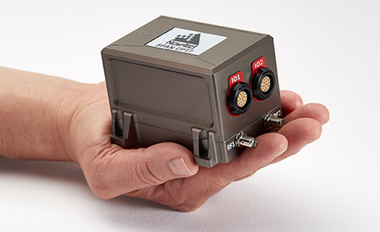
The SPAN CPT7. (Photo: NovAtel)
The firmware works best with the recently launched TerraStar-X correction service, which delivers accuracy and reliability, as well as the OEM7, SPAN CPT7 and PwrPak7 products, which use signals from all GNSS constellations and frequencies to provide users with reliable autonomy and exceptional positioning availability.
The 7.07.03 firmware offers a significant improvement to the SPAN GNSS + INS (inertial navigation system) technology. SPAN with 7.07.03 shows improvements of up to 20% in the horizontal position over the entire SPAN IMU catalog and across various industry use cases including agriculture and marine. SPAN with 7.07.03 also provides improved motion detection, resulting in more robust time to convergence.
“The 7.07.03 firmware features improvements to both our SPAN Marine and SPAN Rail profiles that will greatly impact application performance and consistency,” noted NovAtel Director of Product Management, Neil Gerein, “The SPAN Marine Profile sees improvements to the heave performance and will allow users to start their work significantly faster thanks to a simplified setup for applications in marine dynamics. The SPAN Rail Profile improves position accuracy over long GNSS outages, which is crucial for applications in rail environments that often deal with potential signal obstructions such as trees, tunnels and dense urban areas.”
To download the 7.07.03 firmware update for your platform, click here.
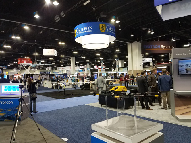
AUVSI Xponential was a big show once again — 8,500 attendees, more than 600 exhibitors, 200 educational sessions and 400 speakers. The show floor was huge as usual, with virtually every kind of UAS product and service imaginable for inspection at small, large and larger booths or display areas.
The morning kick-off presentation on Tuesday was enthusiastic about the coming large-scale adoption of drones and associated robotic technology, with a couple of real-time examples — driverless vehicles at Babcock Ranch in Florida and drone supply deliveries for humanitarian aid in Rwanda.
A view of show floor.
However, there still remain a number of barriers to wide-scale integration of drones into daily life from a regulation perspective, as Steven Bradbury, general counsel of the U.S. Department of Transportation, pointed out — while at the same time also indicating that the Federal Aviation Administration (FAA) has granted hundreds of waivers where the safety case has been adequate for lots of commercial UAS operations.
Most of the major GNSS players were exhibiting at the show, so we focused on gathering their news while also collecting a flavor of the many drone system suppliers in attendance.
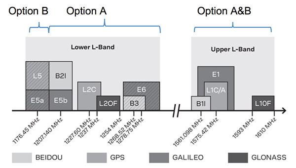
U-blox introduced its new ZED-F9P multi-band, multi-constellation chip — with GPS, GLONASS, Galileo and BeiDou signal reception and processing and on-chip multi-band RTK with fast convergence times — promising centimeter-level accuracy and low 85 mA (4x GNSS) power consumption in a 17 mm x 22 mm package.
ZED-F9P signals: coverage added in two stages. Option A – available now. Option B – available Q2/2020.
Initial urban testing in Finland in challenging conditions has indicated RTK performance at 9 cm 94%, with high availability, short convergence times (<10 seconds) and fast reconvergence. This kind of performance is apparently initially targeted at automotive applications — u-blox is a member of the Sapcorda automotive group — and is forecasting samples for this July, with production beginning before the end of this year.
The NovAtel tagline for the show was “Assured PNT,” which matches many U.S. and International agency objectives — this was accompanied by several announcements for both commercial and government agency products and applications.
The integrated E1 package includes NovAtel’s SPAN technology, which optimizes positioning and attitude performance during extended GNSS outages. Both new PwrPak enclosures come with the Interference Toolkit advanced interference detection and mitigation capability.
With most UAVs, the electronics on the airframe can produce a disruptive internal interference environment, and can lead to potential problems for the integration of sensitive GNSS. To help overcome this issue, NovAtel has released the OEM7600 receiver board in an extremely small form factor, enclosed with protective shielding to reduce the effects of emissions from nearby electronics.
The 7600 comes with 555 channels, multi-frequency/constellation positioning; L-band support for TerraStar corrections; serial, USB, CAN and Ethernet interfaces; advanced interference detection and mitigation features; RTK; GLIDE and Steadyline firmware options with 20-g vibration rating and the option to add integrated SPAN GNSS + inertial.
NovAtel also announced Inertial Explorer Express, which provides the same core processing and utilities as Waypoint Inertial Explorer software for applications including unmanned aerial vehicles (UAVs) and smaller projects. Inertial Explorer Express will produce centimeter-level position and attitude solutions for lidar, camera and other sensor data with faster processing times and reduced complexity.
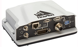
On the government/agency business side of the house, NovAtel has been quite successful with the GAJT antenna, which includes integrated anti-jam technology. GAJT is in use operationally and has been shipped to 16 allied nations around the globe, with the latest success being with the artillery Observation Post Vehicles (OPV) for the Canadian Army.
The NovAtel GAJT-710ML GPS anti-jam antenna.
The Type 26 Frigate of the British Fleet will use NovAtel anti-jam technology. (Photo: BAE Systems)
Canadian OPVs are used on the front-line of combat, so its essential that their location and timing information should not be compromised by enemy jammers. The NovAtel GAJT is readily retrofitted to existing vehicles to provide the necessary jamming defense needed by front-line forces.
Previously, NovAtel also announced the selection of GAJT for the UK fleet of Type 26 Frigates – providing essential anti-jam protection for its onboard navigation system.
MB-Two module by Trimble.
Chris Wheeler and Omar Subra were good hosts when we visited them at the Trimble booth — Chris first made a YouTube video for GPS World (see below) and then gave me some insights into what’s new.
Basically, the OEM line has rolled over new versions of almost all individual receiver boards, with the addition of the BeiDou B3 frequency, capability for RTX PPP (precise point positioning) corrections, the addition of new constellations and inertial integration options.
An updated MB-Two receiver module can be configured for single frequency GPS through to dual frequency GPS, GLONASS, QZSS, Galileo and Beidou, uses RTX PPP and has an improved RTK engine for cm positioning from a base-station, or from over-the-air RTK corrections, or provides relative RTK against a moving base.
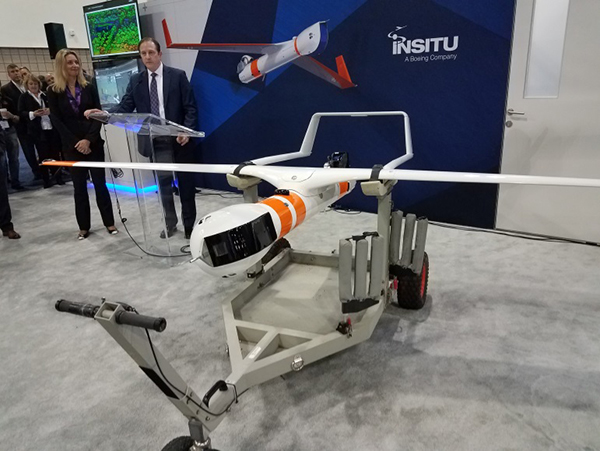
A typical Trimble application could include capturing an Insitu ScanEagle UAV in a difficult shipboard multipath environment with integrated GNSS-inertial, UAV navigation and control, UAV payload stabilization, or providing a “truth-system” for autonomous unmanned ground vehicles.
Since last year when Trimble introduced a “cell-phone” software receiver application, one useful application could have involved an insurance company using a “pocket-carried” antenna (with integrated RF) for field incident assessments. The cell-phone software license would be transferable to other assessors in the department, while a few pocket antennas are available for the whole assessment crew. This saves purchasing a whole load of hardware, and being limited to where the functionality can be moved or deployed. Everyone has a cell phone, and the relatively inexpensive antenna/RF can be available to all needing them.
Watch this video to learn about Trimble’s latest products, including its BD990 and BD992 GNSS receiver boards.
Trimble is also ramping up its OEM customer service and repair capabilities to improve turn around for multiple customers and applications in the field. Improved results are beginning to help customers and its OEM business, while increased R&D investment is expected to put new products into the field in the fall.
This year Intel’s emphasis continued to be on how to manage the huge amount of data that high-precision visual and multi-spectral cameras are gathering by UAVs carrying out asset inspections for their customers. The Intel view is that this data is useless to an end-user unless it is interpreted and presented in a format that can be readily understood and used for the purpose it was intended.
Let’s say a company operates 75 drones inspecting installations it owns or operates across several states, and that 50 GB of data is the nominal amount of data each drone collects on each mission. That means that nearly 4 TB of data could be collected daily if all 75 drones operate at once. More likely, over 1 TB daily shows up in a central location — a huge amount of unprocessed data.
In a live demonstration, Intel showed how a typical installation inspection — by a drone taking high-resolution still photos at a remote location – could be collected and managed. Once in an Intel processing environment, the data quickly became visual format in 2D or 3D, and could be accessed remotely by an inspection team, saving significant travel costs and time to actionable results.
Intel also promised to soon exceed its record at the Pyeongchang Winter Olympics for the number of drones flown at once — currently set at 1,218 drones. The company’s next target is for a light display using 1,500 multi-colored drones.
Insitu CEO Esina Alic
Insitu held a media event at the show to announce its ScanEagle-3 drone system. Esina Alic, the new Insitu CEO, led a team who introduced and then unveiled the new commercial-standard ScanEagle variant.
This new variant has grown out of 20 years of experience and 15 years of working with the FAA to enable integration of drones into the U.S. National Airspace System (NAS). The ScanEagle-3 (SE-3) has been rebuilt with the objective of developing a certifiable vehicle with increased payload and endurance capability that is free of any ITAR restrictions — allowing export without restrictions to the rest of the world.
Insitu unveils the ScanEagle-3 is at Xponential 2018.
SE-3 features include:
Significantly increased (x2) payload
Still provides for full integration of all existing payloads
Commercial, non-ITAR product for the global market
Long-endurance platform
Service contracts available
Product release in Q2 2019
Fully compatible with existing launch and recovery systems
Around ~100 lb without payloads
ScanEagle variants were used in emergency response to the California wildfires at Santa Rosa and Medicina, gathering real-time information for fire-line combatants.
ScanEagle helped fight these wildfires using High Accuracy Photogrammetry (HAP) sensors. Military-grade electro-optical (EO) cameras during daylight and infrared (IR) cameras for night-time imaging extended the time available for tracking fire lines. Penetrating smoke or darkness, these UAVs gathered video and still images that were used to create geo-referenced, high-resolution digital fire progression and suppression maps to guide firefighting on the ground.
This small overview of Xponential 2018 attempts to provide a flavor of the breadth of activity we saw at the show last week. A good portion of this has also been captured through short videos published on the GPS World website, along with news articles.
There is more to come, with a report to follow from the show on Septentrio’s new product releases, Spirent’s GNSS simulation demo, DJI’s overview of drone products featured at the show, CyPhy Works tethered drones, Swift’s announcement of its Skylark correction service trials, Hemisphere’s new Vector Smart Heading Antenna, and Harxon’santennas for drones.
A big show to cover, that’s for sure! It’s a good sign that people were perhaps talking more business than in previous years and a sign that the UAS industry is perhaps moving into its next growth phase.
Exploring IMU specifications and correlating them to performance of a final product can be daunting, as differences between MEMS sensors are not always apparent. This article presents achievable performances in fusion technology across a range of IMUs among the best in their respective performance categories.
The number of available options in inertial navigation systems (INS) has grown substantially over the last several years. Major advances have been made not only in inertial measurement unit (IMU) technology, but also in the ability to exploit sensor information to its fullest extent. In both cases, the largest impact can be seen in the micro-electrical-mechanical systems (MEMS) sensors. MEMS sensors are typically much smaller, lower power and less expensive than traditional IMUs. The net result of these improvements is a proliferation of INS systems at much lower cost than were previously available and, therefore, greatly increased accessibility to technology that has historically seen limited deployment. Selecting the appropriate sensor and fusion solution for a particular application can be very challenging due to the large and confusing spectrum of solutions.
The IMUs will be examined in the context of new enhancements to sensor fusion algorithms such as the use of INS profiles. The concept of INS profiles applies environment specific constraints to improve performance in certain types of vehicles, or motion profiles. External sensors such as odometers and dual antenna operation can also aid the solution considerably, but will be unused in this analysis except for occasional comparisons. These external aiding sensors are extremely helpful in many cases and are available to use with a proprietary tightly coupled GNSS+INS solution called SPAN, but this paper seeks to evaluate what performance can be achieved without such aids.
Real-world test results will be examined using a selection of IMUs with the latest SPAN algorithms to illustrate what kind of performance can be achieved with different sensors in difficult conditions. Despite their major advances over the past few years, there are many challenges involved with utilizing MEMS technology to provide a robust navigation solution, particularly during limited GNSS availability or low dynamics. The measurement error characteristics of these devices have improved dramatically, but are still much larger and more difficult to estimate than traditional sensors. Advancements in SPAN sensor fusion algorithms have enabled these smaller sensors to achieve remarkable performance, especially in applications where environmental conditions allow for additional constraints to be applied.
This testing focuses on the land profile, meaning the constraints applied to a fixed-axle vehicle. The test scenarios were selected in such a way as to provide results for ideal, poor and completely denied GNSS coverage.
INS Profiles
GNSS and IMU sensors are only one part of the overall INS system performance. The sensor fusion algorithms used to exploit the available sensor data to its utmost capability are equally as important. In this regard, several improvements have been made to the SPAN INS algorithms to enhance performance under a variety of scenarios.
The largest addition to the SPAN product line is the introduction of INS profiles. That is, environment- and vehicle-specific modeling constraints can be utilized to enhance the filter performance. For example, the land profile, which will be examined in depth in this article, is intended for use with ground vehicles that cannot move laterally. The assumptions introduced for land vehicles, however, are not necessarily valid for different forms of movement, such as those experienced by a helicopter. Therefore, profiles have been implemented via command, and controlled as required by the user, allowing for maximum performance depending on the application at hand.
The land profile is analogous to what has historically been identified as dead reckoning. It is a method that uses a priori knowledge of typical land vehicle motion to help constrain the INS error growth. In other words, it makes assumptions on how land vehicles move to simplify inertial navigation from a six-degree-of-freedom system to something closer to a distance/bearing calculation. The land profile takes the concept of dead reckoning, models it as an update type into the inertial filter and adds a few additional enhancements.
Velocity Constraints / Dead Reckoning. Amongst other optimizations, the land profile enables velocity constraints based on the assumption of acceptable vehicle dynamics. This includes limiting the cross track and vertical velocities of the vehicle. Of all the enhancements, this is the one most colloquially referred to as dead reckoning.
In its simplest form, dead reckoning is the propagation of a position without any external input. In this forum, external input generally refers to GNSS satellites. Without external input, dead reckoning is inherently dependent on assumptions of velocity and heading to propagate the position. These solutions have evolved by integrating inertial and directional sensors to provide more local input and improve the solution propagation. This also is not a perfect method, however, as inertial sensors have their own errors that grow exponentially over time. The land profile velocity constraints explain the bulk of optimizations SPAN has made to enable dead-reckoning performance in extended GNSS outage conditions.
Explaining the velocity updates involves using the current INS attitude (); the vehicle attitude ( ) is estimated by applying the measured or estimated IMU body to vehicle direction cosine ( ). From this, the pitch and azimuth for the vehicle is estimated.Using the magnitude of the measured INS velocity in conjunction with the derived vehicle orientation, the vehicle velocity is computed, allowing the expected vertical velocity and cross-track to be constrained.
A velocity vector update is then applied to the inertial filter to constrain error growth. The effects of this method are expected to be most apparent in extended GNSS outage conditions when the INS solution must propagate with no external update information.
Phase Windup Attitude Updates. Some applications are inherently difficult for inertial sensors due to the fact that these systems are reliant on measuring accelerations and rotations in order to observe IMU errors. When traveling at a constant bearing and speed, separating IMU errors from measurements becomes challenging, so any application that does not provide meaningful dynamics is more demanding on inertial navigation algorithms. This type of condition commonly appears in applications such as machine control, agriculture and mining.
Gravity is a strong and fairly well known acceleration signal, so the real difficulty in this type of environment is managing the attitude, and especially azimuth, errors. Attitude parameters become difficult to observe when the system experiences insignificant rotation rates about its vertical axis.
External inputs can be used for providing input during low dynamic conditions when rotational observations are weaker. These are particularly helpful in constraining angular errors and include the same types used to assist in initial alignment: dual antenna GNSS heading, magnetometers, etc. However, as the goal of this testing is to demonstrate the achievable performance from a single antenna GNSS system, this type of external aid was specifically omitted.
Utilizing a patented technique for determining relative yaw from phase windup, the system is able to distinguish between true system rotation and unmodeled IMU errors during times of limited motion. This is a novel way to extract additional information out of existing sensors rather than adding more equipment and complexity.
The phase windup update is used to constrain azimuth error growth during low dynamic conditions that are typically not favorable to inertial navigation. However, it does require uninterrupted GNSS tracking and is therefore applicable only in GNSS benign environments. This approach is expected to show the greatest benefit in low dynamic conditions and be directly attributable to azimuth accuracy, but only in conditions where GNSS availability is relatively secure.
Equipment and Test Setup
We paired OEM-grade GNSS receiver cards with a selection of IMUs in different performance categories. Since the OEM GNSS platform is capable of tracking all GNSS constellations and frequencies, we configured each receiver to use triple frequency, quad-constellation RTK positioning. The receivers were coupled with a wideband antenna capable of tracking GPS L1/L2/L5, GLONASS L1/L2, BeiDou B1/B2 and Galileo E1/E5b signals.
Three IMUs were tested: an entry-level MEMS IMU (UUT1), a tactical-grade MEMS IMU (UUT2) and a high-performance fiber-optic gyro-based IMU (UUT3).
All GNSS receivers and IMUs were set up in a single test vehicle and collected simultaneously for all scenarios. IMUs were mounted together on a rigid frame, and all receivers ran the same firmware build that were connected to the same antenna.
The tests were conducted using a single GNSS antenna with no additional augmentation sources, such as distance measurement instrument (DMI) or wheel sensor. These are extremely helpful in aiding the solution, but as previously mentioned, this testing seeks to demonstrate the possible performance without the benefit of additional aiding sources. Dependence on aiding sources is a very important distinction when comparing such systems.
The GNSS positioning mode used was RTK via an NTRIP feed from a single base station with baselines between 5–30 kilometers. This was done to try to minimize GNSS positioning differences between the three systems. L-band correction signals were not tracked, and PPP positioning modes were not enabled.
A basic setup diagram of each system under test can be seen in Figure 1.
FIGURE 1. Equipment set-up (not to scale).
Test Scenarios
Four test scenarios will be examined using all the equipment and algorithms described above. They are: urban canyon, low dynamics, parking garage and extended GNSS outage.
The urban canyon test is designed to show the performance of the system in restricted GNSS conditions. The challenge to this scenario is to maintain a high-accuracy solution when GNSS positioning becomes intermittent or even unavailable.
The low dynamics test is intended to illustrate the benefits of the land profile, and specifically the phase windup azimuth updates in maintaining the azimuth accuracy.
The parking garage test will show the efficacy of the velocity constraint models over the different IMU classes as the extended outage provides no external information to the INS filter whatsoever. Again, no other aiding sources were used.
Urban Canyon Test. The urban canyon environment has been and remains one of the strongest arguments in favor of using GNSS/INS fusion in a navigation solution. Because urban canyons are common, densely populated and, of course, a demanding GNSS environment, they represent both an important and challenging location to provide a reliable navigation solution. Typically, they contain major signal obstructions, strong reflectors and complete blockages (depending on the city). For this reason, they provide an excellent use case for INS bridging to maintain stability of the solution.
During most urban canyon environments, it is typically rare to incur total GNSS outages of more than 30 seconds. Therefore, this scenario examines the stability of the solution in continuously degraded, but not generally absent, GNSS. In this case, the coupling technique of the inertial algorithms rather than quality of the IMU dominates achievable position accuracy.
The receiver platform is capable of tracking all GNSS constellations and frequencies. This provides a significant benefit to test scenarios, such as the urban canyon, where the amount of visible sky is significantly restricted. In this case, the more satellites that are observable, the more the tightly coupled architecture can exploit the partial GNSS information.
Though position accuracy between IMUs is less apparent in this condition, attitude results remain separated by IMU quality, which is a major consideration for some mapping applications such as those using lidar or other sensors where a distance/bearing calculation must be done for distant targets.
Test data for this scenario was collected in downtown Calgary, Canada. The trajectory (Figure 2) includes several overhead bridges for brief total outages and some very dense urban conditions.
FIGURE 2. Urban canyon test trajectory.
Table 1 shows the RMS error results of the three systems running both the default and land profiles. The first thing to notice is that the errors are differentiated by IMU category, though the differences are fairly small in the position domain thanks to the tightly coupled architecture. However, because GNSS information is partially available, the differences seen in activating the land profile are fairly modest, especially as the IMU performance rises.
TABLE 1. RTK RMS errors for urban canyon.
As the clearest benefits of the land profile are seen on the entry-level MEMS IMU (UUT1), these will be explored graphically in Figures 3 and 4. Figure 3 shows the position domain, and the RMS differences can be seen in a few cases where the default mode errors increased faster than the land profile. An example of this divergence is most obvious around the 1500-second mark of the test during periods GNSS is most heavily blocked.
FIGURE 3. UUT1 position error (std vs. land). Source: GNSS
FIGURE 4. UUT 1 attitude error (std vs. land). Source: GNSS
Low Dynamics Test. The low dynamics test is designed to emulate conditions experienced by machine control, agriculture and mining applications. In this situation, GNSS availability is generally not the limiting factor and can be used to control the low frequency position and velocity errors of the INS system. The difficulty is managing the attitude, especially azimuth, errors because attitude parameters are very hard to observe without significant rotations or accelerations (Figures 5 and 6).
FIGURE 5. Low dynamics test trajectory. Source: GNSS
FIGURE 6. Low dynamic UUT1 position errors. Source: GNSS
The low dynamics test was collected in an open-sky environment and consisted of traveling in a straight line on a rural road for roughly 2 km at an average speed of 10–15 km/h.
As this type of scenario provides little physical impetus, the azimuth and gyroscope biases are not observable. The reason for this is due to the use of the first-order differential equations to estimate the navigation system errors. Essentially, the differential equations define how the position, velocity and attitude errors change (grow) over time based on each other and the IMU errors. The observability of a particular update is tied to additional states through the off-diagonal elements of the derived transition matrix with the accelerations and rotations experienced by the system.
The overall RMS solution errors for RTK are provided in Table 2. As evident by the results presented, the position and velocity errors are clearly constrained by the continuous RTK-level GNSS position regardless of whether the land profile is enabled or not. The real differentiator in the land profile is the attitude performance due to the use of phase windup as a constraint. Moreover, the attitude improvements are certainly tied to IMU quality.
UUT1 exhibited a noticeable improvement in the attitude performance, while the higher performance IMUs did not. This is not entirely unexpected as the precision of the phase windup is lower than that of the higher grade IMUs.
Looking at the data graphically, Figure 7 shows the effect of land profile on positioning performance in this scenario. The two solutions are indistinguishable on the plot, and are all within standard RTK-level error bounds as was indicated in the RMS table.
Figure 7 shows the attitude accuracy with and without the land profile enabled. Again, the largest gains are seen on the entry-level UUT1, so this is the graphic shown below. This shows how the error peaks of the azimuth estimates are constrained. All the sharp corrections in each plot correspond to the vehicle turning around at the end of each 2-Km line and illustrates how much more powerful a rotation observation can be in azimuth accuracy overall.
FIGURE 7. UUT1 attitude error (std vs. land).
Parking Garage Test. This test was carried out at the Calgary International Airport and was selected to show the INS solution degradation during extended complete GNSS outages. The test consisted of an initialization period in open sky conditions to allow the SPAN filter time to properly converge, followed by a 500-second period within the parking garage. During the interval within the parking garage there were no GNSS measurements available.
Figure 8 provides a trajectory of the test environment. The time spent inside the parking structure is evident on the center bottom of the image.
FIGURE 8. Parking garage test trajectory.
Unlike urban canyon environments that contain partial GNSS information, this exhibits an extended period of complete GNSS outage. During this type of scenario, the IMU specifications become much more significant. IMU errors directly translate to the duration the solution can propagate before the accumulated low-frequency errors of the IMU grow to unacceptable levels. System performance during the outage degrades according to the system errors at the time of the outage and the system noise. The velocity errors increase linearly as a function of attitude and accelerometer bias errors. The attitude errors will increase linearly as a function of the unmodeled gyro bias error. The position error is a quadratic function of accelerometer bias and attitude errors.
Position results from each IMU are shown for UUT 1 in Figure 9. This plot shows the error with the land profile on and off. Without the land profile, the second-order position degradation in an unconstrained system is clearly visible.
FIGURE 9. UUT1 position error (std vs. land ).
By enabling the land profile, the filter constrains IMU errors by utilizing a velocity model for wheeled vehicles. With the constraints, the position errors are startlingly reduced for UUT1 and then progressively less impactful as the IMU quality increases in UUT2 and UUT3, respectively. This makes sense as the IMU error growth is progressively smaller in those IMUs, so the effect of mitigating them is also reduced.
Extended GNSS Outage Test. An extension of the parking garage test is to evaluate the performance in a much longer outage. Instead of 10 minutes, an outage of one hour was tested. Also, due to the extremely long GNSS outage bridging, the effects of adding a DMI sensor (odometer) will also be explored as they are able to be used as a major additional aiding source.
The most common measure of dead-reckoning performance is error over distance traveled (EDT). Due to the very long duration outages in this test, the errors will be reported in error over distance traveled to conform to the typical reporting method. This test was conducted in a mixture of highways and suburban streets with an average speed of 65 Km/h, incorporating a moderate amount of dynamics.
This effect can be seen over the duration of the entire outage as well in Figure 9. In this case, the points are the RMS error over several tests. and the light background shroud represents the one-sigma confidence as time progresses. The confidence increases over time as the overall distance traveled also increases.
FIGURE 10. Land profile EDT with and without DMI aid over 1-hour GNSS outage.
Results and Conclusions
In testing a range of IMUs in some challenging scenarios, this paper has sought to illustrate what kind of performance is achievable using each kind of system. An added complexity is looking at what effect certain inertial constraint algorithms have on this solution.
Although low-cost MEMs IMUs are continuing to greatly improve in quality and stability, the end application is still highly correlated to the overall performance of a selected INS system. For a great many applications, the MEMS devices in combination with a robust inertial filter can meet requirements and provide excellent value. However, some applications continue to require higher end sensors, and possibly post-processing to meet their needs.
The ability of SPAN to utilize partial GNSS measurements such as pseudorange, delta phase and vehicle constraints means even low-cost MEMs are capable of providing a robust solution in challenging GNSS conditions. However, this tightly coupled integration is limited in cases where GNSS is completely denied or when in low dynamic conditions.
INS profiles using velocity constraints, phase windup and robust alignment routines have been shown to provide substantial aid to the INS solution in tough conditions, such as GNSS denied or low dynamics. These improvements were shown to exhibit greater impact as the IMU sensor precision decreases. These abilities, in conjunction with the existing tightly coupled architecture of SPAN and the ever-increasing accuracy of MEMS, IMUs indicate that robust GNSS/INS solutions will continue to proliferate at lower cost targets. However, very precise applications such as mapping will continue to rely on higher quality sensors to meet strict accuracy requirements.
ACKNOWLEDGMENTS
The authors thank Trevor Condon and Patrick Casiano of NovAtel for collecting and helping to process the data presented in this article, and to Sheena Dixon for her tireless editing.
Manufacturers
NovAtel SPAN technology on the NovAtel OEM7 receiver is the testing and development platform for this research. NovAtel OEM7700 GNSS receiver cards and a NovAtel wideband Pinwheel antenna were employed. The inertial units under test were an Epson G320 (low-power, small-size MEMS IMU); Litef μIMU-IC (larger tactical-grade performance IMU still based on MEMS sensors); and a Litef ISA-100C (near navigation-grade IMU using fiber-optic gyros (FOG). Although all are excellent performers in their class and capable of providing a navigation-quality solution, the intent is to show the potential limitations that might arise due to the intended application.
RYAN DIXON is the chief engineer of the SPAN product line at NovAtel Inc., leading a highly skilled team in the development of GNSS augmentation technology. He holds a BSc. in geomatics engineering from the University of Calgary.
MICHAEL BOBYE is a principal geomatics engineer at NovAtel and has participated in a variety of research projects since joining in 1999. Bobye holds a BSC. in geomatics engineering from the University of Calgary.
NovAtel Inc. is showcasing its high precision positioning technology as part of AutonomouStuff’s “Roadmap to Autonomy” exhibit at the 2017 Consumer Electronics Show (CES), Jan. 3-8 in Las Vegas. The exhibit is located at the MGM Grand in the Skyline Terrace Suite.
AutonomouStuff provides research and development platforms for the safe and reliable testing of automation technologies.
It uses NovAtel’s exceptionally robust SPAN GNSS + Inertial (INS) technology to provide the highly precise, continuous 3D positioning necessary to evaluate robotic and autonomous solutions for autonomous applications.
NovAtel’s SPAN technology combines a high-performance Global Navigation Satellite System (GNSS) receiver with an Inertial Measurement Unit (IMU) to deliver deeply-coupled centimeter-level positioning. SPAN provides robustness against short GNSS outages, using IMU updates to bridge the positioning solution. SPAN also provides high data rate position, velocity and attitude (pitch, roll, heading) updates to capture the full real-time motion profile of a vehicle. Widely deployed in the automotive R&D space, SPAN supports applications ranging from autonomous navigation to V2X systems, where it is utilized to provide a source of vehicle ground truth.
As a committed technology partner, NovAtel has worked closely with AutonomouStuff to optimize SPAN for AutonomouStuff’s vehicle perception kits. As a result of these efforts, AutonomouStuff is able to offer three different levels of positioning performance — “good, better, best” — based on the grade of IMU selected.
“We are always excited to work with the team at NovAtel and cannot wait to show off their ‘good, better, best’ SPAN GNSS options for autonomy in our suite at CES,” said AutonomouStuff CEO Bobby Hambrick. “Their solutions are a significant piece of autonomous research and development. With three kit options, there is something for everybody. We’ve done the work for you, allowing you to choose which kit is best for you based on your accuracy needs and price range.”
The collaboration with AutonomouStuff is reflective of NovAtel’s commitment to the development of fully autonomous vehicles for a wide range of industries. In May 2016, NovAtel announced the formation of a new Safety Critical Systems (SCS) Group, tasked with developing functionally safe GNSS positioning products that will meet the exceptional performance and safety requirements of autonomous vehicles.
“Our team made significant progress in 2016 towards product definition, GNSS integrity for automotive applications, and corporate TS 16949 compliance,” said Jonathan Auld, Director of the SCS Group at NovAtel. “As the world leader in high precision GNSS technology for more than 20 years, NovAtel is leveraging its extensive experience developing safety critical systems for the aviation industry to meet the future safety thresholds required for driverless cars.”
AutonomouStuff and NovAtel representatives will be available in the MGM Grand Skyline Suite during the CES to answer customer questions. To set up a meeting with the NovAtel SCS team at CES 2017, attendees can contact Allan MacAulay, Business Development Manager, SCS ([email protected]).
NovAtel’s SPAN GNSS/INS technology is now available on the company’s OEM625S dual-frequency SAASM GPS plus civil RTK receiver. The addition of SPAN offers system developers with SAASM requirements the benefit of continuously available 3D positioning, velocity and attitude (roll, pitch, yaw) for their U.S. Department of Defense (DOD) applications.
Authorized defense customers need access to the Precise Positioning Service (PPS) for DOD applications. When keyed, the existing OEM625S board level receiver provides an RTK PPS solution by taking the raw measurements from an L-3 XFACTOR SAASM and applying them to NovAtel’s industry leading RTK algorithm. SPAN technology couples NovAtel’s precision GNSS receivers with robust IMUs to provide a more reliable, stable solution, even during short periods of time when satellite signals are blocked or unavailable. The company offers a range of IMU options to meet the accuracy and size requirements for nearly any defense application.
NovAtel’s FlexPak-S enclosure.
SPAN technology is also available on NovAtel’s FlexPak-S enclosure, with multiple RS-232/RS422 serial ports for ease of integration.
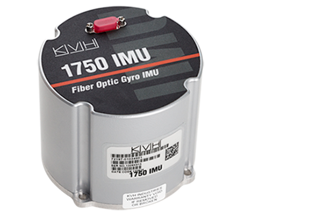
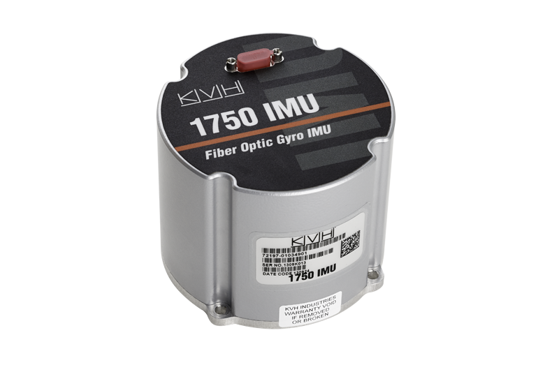
NovAtel, Inc., has added the IMU-KVH1750 as an inertial measurement unit (IMU) option in its SPAN GNSS/INS line of positioning products. The IMU-KVH1750 is a high-performance commercial off-the-shelf (COTS) sensor that offers excellent bias stability and repeatability, NovAtel said. It incorporates KVH’s DSP-1750 precision fibre-optic gyro with very low noise MEMS accelerometers.
Commercially exportable, the IMU-KVH1750 integrates easily with NovAtel’s OEM6 series of receivers to provide a tightly coupled 3D navigation solution, the company said. Offering customers continuous position, velocity and attitude (roll, pitch and azimuth) measurements, a SPAN system is stable and available even through periods when satellite signals are blocked or unavailable.
The IMU-KVH1750 supported SPAN system is designed for mobile and airborne mapping applications as well as hydrographic survey. It can be relied on to provide accurate, continuous performance in harsh environments, and features excellent shock vibration and thermal functionality.