System Design & Test
Galileo Test Bed
Over the past few years, GATE has become well known for being a top-level Galileo test and development range worldwide. It is operated by IFEN GmbH under contract of the owner DLR (German Aerospace Center). The GATE test bed offers a wide range of possibilities for navigation test scenarios with realistic Galileo signals on three frequencies simultaneously in an outdoor environment. Although the test range is, of course, a ground-based infrastructure in the Berchtesgaden Alps, the certified GATE system is able to transmit the original navigation signals from eight “virtual” Galileo satellites. This also includes the simulation of natural influences such as ionosphere or troposphere delays, the adaptation of other signal characteristics, as well as effects of signal strength. Furthermore, GATE includes the capability to induce dedicated “Feared Events” and alerts for one or several satellites of the simulated Galileo constellations.
IFEN
 Machine Control
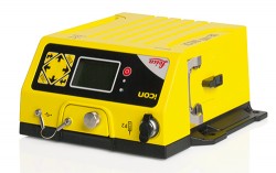
Machine Receiver
The Leica iCON gps 80 GNSS machine receiver offers features and benefits for system integrators looking for powerful, reliable, and future-proof GNSS machine receivers. It increases the overall performance of the iCON machine control system, allowing users to work more productively. Besides Galileo, signals tracked include GPS, GLONASS, and BeiDou. The iCON gps 80 increases the overall performance of the system, so that the uptime of dozers, excavators, drilling and dredging machines, wheel loaders, graders, and pavers is maximized with fast, reliable 3D positioning and productive operation by a perfectly tuned machine control system.
xRTK allows machine guidance in difficult environments, increasing machine productivity. Leica iCON telematics provides remote access to the machine computer for fast data transfer and support.
Leica Geosysems
 Simulation
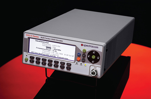
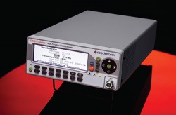
GNSS Signal Generator
The GSG-51 GNSS signal generator provides a fast and cost-effective solution for production testing for Galileo and other GNSS. It emulates a single GNSS signal and can be upgraded for Galileo, as well as to increase the channel count, add receiver trajectory control, and add advanced features such as SBAS (WAAS, EGNOS,MSAS, or GAGAN), white noise generation, or multipath simulation. Its main application is a simple but very fast manufacturing test, to assure that the assembly is correct, that the antenna is properly connected, and that the receiver can receive and identify a satellite signal, for instance, in mobile phones with integrated GNSS receivers.
With a wide RF level range from –65 to –160 dBm, the sensitivity of all types of GNSS receivers can be verified with a minimum of delay. The 60-dB of extra power from normal test scenarios allows for splitting the signal many times.
Spectracom
 Space Weather Monitoring
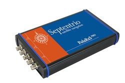
Multi-Constellation Receiver
The PolaRxS is a multi-frequency, multi-constellation receiver dedicated to ionospheric monitoring and space weather applications. It features simultaneous high-quality tracking of all visible signals (L1, L2, L5, E5ab/AltBOC GPS/GLONASS/Galileo/Beidou/SBAS) at low noise levels. The receiver outputs an extensive set of GNSS measurements, including signal phase and intensity at up to 100 Hz, with a phase noise standard deviation (phi60) as low as 0.03 rad.
The A Posteriori Multipath Estimator (APME+) tackles short-delay multipath to enhance the measurement quality, while LOCK+ tracking guarantees robust tracking of rapid signal dynamics during scintillation events. Included tools provide continuous total electron content (TEC) and scintillation indices logging for space weather and ionosphere monitoring.
Septentrio
 Personal Tracking
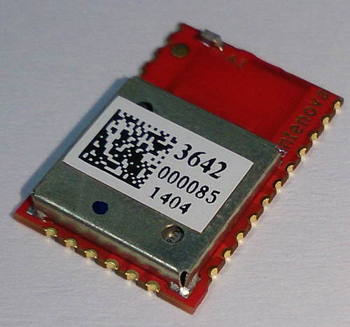
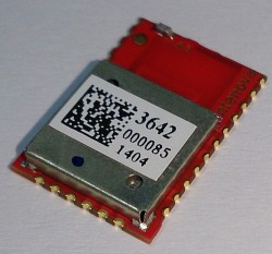
Multi-GNSS Antenna Module for Wireless
The M2M Radionova M10478-A3 antenna module combines a full receiver and antenna on the same ultra-compact module. The highly integrated multi-GNSS RF antenna module is based on the Mediatek MT3333 architecture combined with Antenova’s antenna technology, receiving Galileo as well as GPS, GLONASS, BeiDou, QZSS, and SBAS signals. Using patented external matching means this module is suitable to applications from small watches to smartphones and asset trackers. All front-end and receiver components are contained in a single package laminate base module, providing a complete GNSS receiver for optimum performance.
Antenova
Location-Based Services / Wireless
Software Receiver
A software-based GNSS receiver from Galileo Satellite Navigation (GSN) is available on Tensilica ConnX digital signal processor (DSP) cores, for wireless mobile applications. The GSN GNSS receiver running on a Cadence ConnX BBE16 DSP consumes as little as 10 mW of power on a 40-nm process and has the ability to work in lower rates, or snapshots, for ultra-low-power mobile scenarios. It delivers high-sensitivity tracking, offering a seamless GNSS experience in challenging environments. This provides customers with the ability to upgrade their designs to include future satellite systems, including Galileo. With no additional silicon costs and a low cost of deployment, this software-based solution offers a way to implement satellite navigation functionality in many products where it otherwise might be impractical.
Cadence; Galileo Satellite Navigation
 Asset Tracking
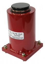
Hazardous Goods Surveillance
The Ulys-Ex2 beacon is a standalone tracking unit providing worldwide location-based alerts for up to seven years, for monitoring of unpowered mobile assets in potentially explosive atmospheres.
With a Galileo-ready u-blox receiver, it provides monitoring data for tank containers and tank-trailer transport operations, increasing the level of security and safety of explosion-sensitive shipments. The beacon is part of a turnkey, real-time dangerous goods monitoring solution adapted to risk environments, guaranteeing global visibility on routing from the production site to the customer delivery point. It is ATEX Zone 1 certified for Europe — Zone 1 is an atmosphere where a mixture of air and flammable substances in the form of gas, vapor, or mist is likely to occur in normal operating circumstances.
Saphymo
 Consumer OEM
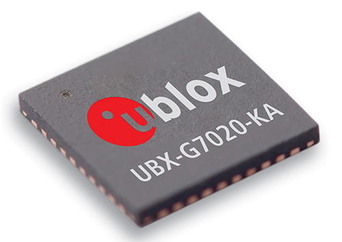
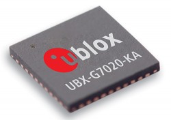
Galileo-Ready Module
The Galileo-ready NEO-M8 series of standalone concurrent GNSS modules is built on the u-blox M8 GNSS (GPS, GLONASS, Galileo, BeiDou, QZSS, and SBAS) engine in the NEO form factor. The NEO-M8 series provides high sensitivity and minimal acquisition times while maintaining low system power. It is optimized for cost-sensitive applications, with the NEO-M8N and NEO-M8Q providing high performance and easier RF integration. Sophisticated RF-architecture and interference suppression ensure maximum performance even in GNSS-hostile environments. The NEO-M8 combines a high level of robustness and integration capability with flexible connectivity options. The future-proof NEO-M8N includes an internal Flash that allows simple firmware upgrades for supporting additional GNSS systems, making the NEO-M8 suitable for industrial and automotive applications.
u-blox
 Professional OEM
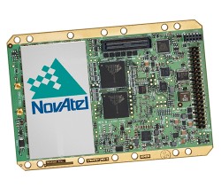
High-Precision Receiver Card
The OEM638 high-precision receiver card tracks all existing and planned constellations including Galileo, GPS, BeiDou, GLONASS, and QZSS. By providing flexible positioning options, from standalone meter-level to AdVanceRTK centimeter-level accuracy, the OEM638 offers the flexibility to meet a wide range of positioning requirements. A powerful API, 4-GB on-board data storage, wide input voltage, and a host of interface options simplifies integration, decreasing time to market and overall system costs. With 240 channels and comprehensive tracking and positioning with all current and planned GNSS signals, the OEM638 is field upgradeable. It offers user configurability for reference station, timing, and other precision positioning applications.
NovAtel
Consumer OEM
 Low-Noise Amplifier
The BGA825L6S is a cost-effective low noise amplifier (LNA) for Galileo and other GNSS. It features an ultra-low noise figure, high linearity, high gain, and low current consumption over a wide range of supply voltages from 3.6V to 1.5V. It is designed for GNSS LNA, as it improves sensitivity, provides greater immunity against out-of-band jammer signals, and reduces filtering requirements, which lowers the overall cost of the receiver. The low noise figure of 0.6 dB is a key parameter for GNSS systems as it directly influences the sensitivity of the system, as well as the time-to-first-fix and time-to-subsequent-fix. LNAs with a lower noise figure enable mobile phones with faster GNSS signal fix and higher end-user satisfaction.
Infineon Technologies AG
 Simulation
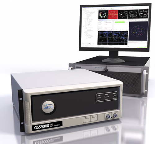
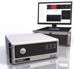
RF Constellation Simulator
The newly released Spirent GSS9000 Multi-Frequency, Multi-GNSS RF Constellation Simulator can simulate signals from all GNSS and regional navigation systems, including Galileo. The GSS9000 offers a four-fold increase in RF signal iteration rate (SIR) over Spirent’s GSS8000 simulator. The GSS9000 SIR is 1000 Hz (1ms), enabling higher dynamic simulations with more accuracy and fidelity. It includes support for restricted and classified signals from the Galileo and GPS systems, as well as advanced capabilities for ultra-high dynamics. It can evaluate resilience of navigation systems to interference and spoofing attacks, and has the flexibility to reconfigure constellations, channels, and frequencies between test runs or test cases.
Hardware changes can be done in the field, supported by the new on-board calibrator module. The GSS9000 is extensible and can support the widest range of carriers, ranging codes, and data streams for the Galileo, GPS, GLONASS, and BeiDou systems, as well as regional/augmentation systems. Multi-antenna/multi-vehicle simulation, for differential-GNSS and attitude determination, and interference/jamming and spoofing testing are also supported.
Spirent
 Transportation
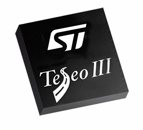
eCall-Ready Positioning Chip
The Teseo II (STA8088 series) is a single-chip positioning device capable of receiving signals from multiple satellite navigation systems, including Galileo, GPS, GLONASS, and QZSS. The Teseo II combines high-positioning accuracy and indoor sensitivity performance with powerful processing capabilities and design flexibility, making Teseo II suitable for eCall, ERA-GLONASS, telematics, handheld, consumer, portable navigation devices, marine, and in-car navigation systems. The Teseo II is being tested by the European Space Agency and the European Commission Joint Research Center for eCall approval. The testing campaign is coordinated by the European GNSS Agency as part of its effort to accelerate Galileo adoption.
While the Teseo II Ihas always had the capability to be Galileo-ready, ST is enabling a firmware update from Galileo that benefits consumers and doesn’t require a hardware modification. The Teseo II chips can simultaneously use signals from multiple satellite navigation systems, including the currently available Galileo satellites, and progressively, as future satellites are launched, the full satellite constellation.
STMicroelectronics
 Professional OEM
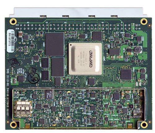
High-Precision Receiver
The 864-channel TRE-3 receiver can simultaneously access all current GNSS signals, with room to spare for multiple-channel tracking of select signals. The new product offers three ultra wide-band (100 MHz) fast sampling and processing, programmable digital filters, and superior dynamic range. After 12-bit digital conversion, nine separate digital filters are shaped for each of the nine bands: GPS L1/Galileo E1, GPS L2, GPS L5/Galileo E5A, GLONASS L1, GLONASS L2, Galileo E5B/BeiDou B2/GLONASS L3, Galileo altBoc, Galilee E6/BeiDouB3/QZSS LEX, and BeiDou B1.
JAVAD GNSS
 Interference Monitoring
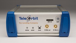
Modular RF Front-End
The GTEC-RFFE is a flexible, portable, and affordable ultra-wideband recording solution that can be adapted to the reception of all GNSS bands available, including Galileo, supporting up to 80 MHz of RF bandwidth. Because of its modular concept, the GTEC-RFFE not only supports a set of pre-selected configurations, it can be set up for multi-antenna inputs, user selectable bandwidth, intermediate frequencies, and customized ADC sampling rates and resolutions. It is designed for development of software-defined radios and receivers, GNSS multi-system signal analysis and comparison, analysis of atmospheric effects such as ionospheric and tropospheric irregularities and scintillation, and interference monitoring for protecting critical operations and infrastructures.
TeleOrbit
 Timing
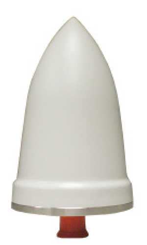
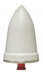
GNSS Timing Reference Antenna
The GNSS1-TMG-26N is a fixed-mount network timing antenna covering Galileo L1, as well as GPS, GLONASS, and Beidou frequencies. It is designed for long-lasting, trouble-free deployments in congested cell-site applications. The low-noise, high-gain amplifier is suited to address attenuation issues associated with applications requiring longer cable runs. The proprietary quadrifiliar helix design, coupled with multistage filtering, provides superior out-of-band rejection and lower elevation pattern performance than traditional patch antennas.
PCTEL
 Professional OEM
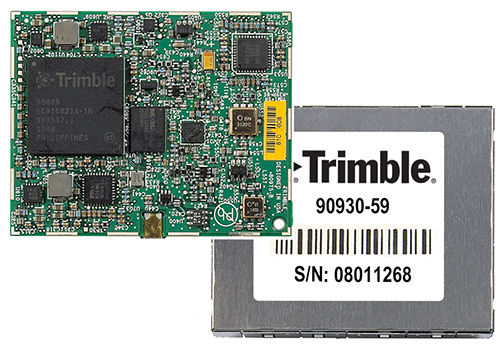
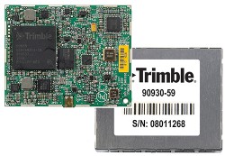
Positioning and Heading System
The Trimble BD930 supports both triple frequency from the GPS and GLONASS constellations, plus dual frequency from Galileo and BeiDou. As the number of satellites in the constellations grows, the BD930 is ready to take advantage of the additional signals to deliver fast and reliable RTK initializations for 1–2 centimeter positioning. Different receiver configurations are available, including autonomous GPS L1 to four-constellation triple-frequency RTK.
Trimble
 Simulation
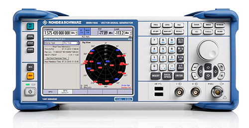
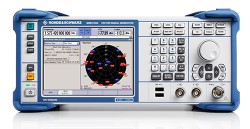
Vector Signal Generator
The R&S SMBV100A vector signal generator can generate Galileo, GPS, and GLONASS signals for up to 24 satellites in realtime. With the SMBV-K107 option, the simulator covers the BeiDou standard as well.
The R&S SMBV-K101 option allows developers in the automotive and wireless communications industries to test GNSS receivers for specific effects such as obscuration and multipath propagation. If the GNSS receiver of a navigation instrument or smartphone is located inside a vehicle, testing must also take into account the obscuring effect of the vehicle’s metal body. The R&S SMBV-K102 option can simulate this obscuration and, if required, the additional antenna pattern.
In addition to test scenarios for A-GPS, smartphone developers have the Assisted Galileo (R&S SMBV-K67) and Assisted GLONASS (R&S SMBV-K95) options at their disposal.
Rohde & Schwarz
 Signal Amplification
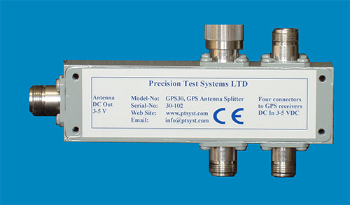
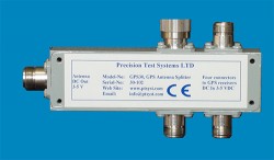
Antenna Amplifier
The GPS35-BNC is an inline antenna amplifier for both the L1 and L2 frequencies of the Galileo, GPS, and GLONASS satellite systems. When connected between the GPS receiver and the GPS antenna, power from the GPS receiver that normally powers the active antenna powers both the active antenna and the GPS-BNC, so no extra power supply is needed. The GPS35-BNC can be used with either active or passive GPS antennas by selecting internal jumpers. The GPS35-BNC provides a gain of 35 dB between 1200 and 1607 MHz. With the GPS35-BNC installed, extra lengths of cable can be used between the antenna and the GPS receiver itself. If low-loss cable is used, cable lengths over 350 meters (1,150 feet) can be used without any degradation to the GPS signal.
The noise figure of the GPS35-BNC is less than 3 dB, and signals in the cellular or mobile frequency bands are rejected by more than 35 dB.
Precision Test Systems