Tag: test track

  • WingtraOne drone maps site for EuroTube high-speed track

    EuroTube is Europe’s first testing ground for high-speed vacuum maglev transportation.

    In May, a WingtraOne drone conducted a topographic survey of a construction site where a EuroTube vacuum high-speed test track will be built.

    The futuristic project is the European answer to its American counterpart Hyperloop of the SpaceX and Elon Musk fame. The EuroTube project plans to provide a 3-kilometer-long vacuum tube to developers of pod technologies for testing.

    The Eurotube test infrastructure for high-speed vacuum transportation will provide an environment free of air resistance to test “pods”, or cars, that can be accelerated to speeds as high as the Boeing 747 in flight. (Photo: EuroTube)
    The Eurotube test infrastructure for high-speed vacuum transportation will provide an environment free of air resistance to test “pods”, or cars, that can be accelerated to speeds as high as the Boeing 747 in flight. (Photo: EuroTube)

    The project proved to be surprisingly challenging from the very beginning. First, the team had to find a long, flat stretch of land for EuroTube’s construction in Switzerland, a country famous for its mountains.

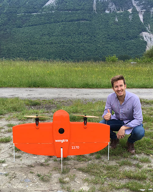
    And just as the right location was found in the canton of Valais, another challenge came along. How to survey such a complicated site surrounded with mountains, water bodies, forests and railway tracks? Luckily, the fellow Swiss company Wingtra already had a solution — the vertical-take-off-and-landing (VTOL) drone WingtraOne.

    After spending months in research and development of prototypes, the team at EuroTube selected the stretch of land in the Valais region of Switzerland as its candidate location. The chosen construction site is located next to railways tracks. A few water bodies, forests and ditches flank the other side of the construction site, making available a mere 3-meter-wide piece of land for take-off and landing of the drone.

    Fortunately, the WingtraOne’s VTOL capabilities were designed with exactly these kind of constraints. But why choose such a peculiar construction site in the first place?

    Bringing Europe’s transportation system to 21st century

    The answer lies in the technology behind the EuroTube itself. One of the main limitations in speeding objects on ground is the high air resistance, also called drag (drag is a type of friction force acting opposite to the relative motion of any object). By maintaining a low-pressure environment or even a vacuum, this air resistance can be lowered drastically, and hence objects can be accelerated to high speeds.

    Technologies such as the EuroTube provide this vacuum environment inside a long tube. Within such tubes, cars called “pods” can be accelerated to speeds as high as 800 km/h, meaning a journey between Zurich and Paris, which currently takes 4 to 6 hours, would be reduced to a mere half an hour. This is the vision driving the EuroTube project, which will provide a 3-kilometer-long vacuum tube to developers of pod technologies for testing.

    Aerial surveying of the construction site

    Gerard Güell, the construction director of EuroTube, at the construction site with the WingtraOne. (Photo: Wingtra)
    Gerard Güell, the construction director of EuroTube, at the construction site with the WingtraOne. (Photo: Wingtra)

    Before the construction of the tube could begin, however, the EuroTube team needed to survey the construction site. Looking at solutions that would cut time and cost, Sascha Mark, the technical director at the EuroTube project, reached out to Wingtra in early May.

    A partnership between Wingtra and EurtoTube was quickly formed where Wingtra would provide the WingtraOne as well as conduct the surveyof the construction site.

    “For a cutting-edge research project involving significant infrastructure, time is of crucial importance,” Mark said. “We were looking at surveying solutions that can provide the dataset required for a construction site quickly without compromising on the accuracy. From this perspective, WingtraOne looked like a viable prospect.”

    The survey was conducted on May 21 when Gerard Güell, the construction director at EuroTube, met Adyasha Dash from Wingtra on site. To survey the area quickly with high accuracy, a WingtraOne equipped with an RX1RII camera and post-processed kinematics (PPK) was chosen. As the survey required flights over a straight, flat piece of land, flight planning was done on site, and took less than 5 minutes for the setup.

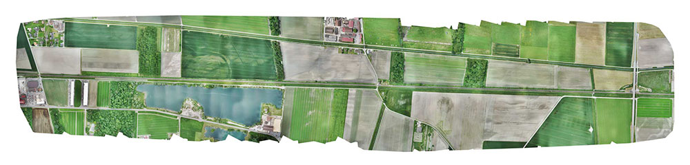
    The wind on site ranged from 2 m/s to 5 m/s. After letting the flight planning app WingtraPilot run a host of automatic pre-flight checks, the drone started its flight to collect aerial imagery at a ground sampling distance (GSD) of 3 cm/px. At the end of two consecutive flights taking less than an hour in total, the drone had collected a little more than 800 individual images.

    “It was nearly effortless to conduct the aerial surveying with the WingtraOne,” Güell said. “All we had to do was to walk to the take-off area, double-check the survey area we wanted to cover on the flight planning app, and hit go.”

    Final orthomosaic generated by the images collected by the WingtraOne: the 3-km long Eurotube will be constructed along the indicated area. (Image: Wingtra)
    Final orthomosaic generated by the images collected by the WingtraOne: the 3-km long Eurotube will be constructed along the indicated area. (Image: Wingtra)

    From aerial imagery to point cloud

    Infographic: Wingtra
    Infographic: Wingtra

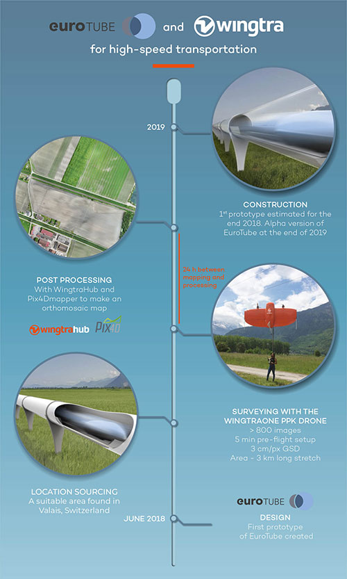
    After two flights, the images were pre-processed with WingtraHub, a desktop app, to add geographical identification metadata to the images. PPK processing was also done in this step. The base file for PPK processing was obtained from Swisstopo, which monitors GNSS receivers at 30 permanent locations in Switzerland. These receivers form the modern-day reference points for positioning and surveying, and help enhance the geolocation information of the images in conjunction with the flight data (hence the name, post-processed kinematics). It took a little more than half an hour to pre-process the entire dataset.

    The images with their accurate geolocation information were then uploaded to Pix4Dmapper to generate a point cloud of the site. All in all, it took less than 24 hours to go from data collection to point-cloud generation, without compromising on the quality of survey itself.

    “We are pleased to say that the dataset gathered by the WingtraOne was precise enough to let the engineering office begin planning construction,” Mark said. “The generated point cloud has a vertical accuracy of 10 centimeters and horizontal accuracy of 3 centimeters. Thanks to the WingtraOne, we are now well on track on our timeline to begin construction.”

    According to EuroTube’s scheduled timeline, a shorter prototype of the tube will be completed at the end of this year, and an alpha tube at the end of 2019. European research and development teams across institutes and universities can then start testing pod technologies to make ultra-high speed transportation systems a reality.


    Adyasha Dash works as a software developer at Wingtra, where she focuses on developing safe flight control and planning algorithms. When she is not tinkering with drones, you can find her writing about the ethics of artificial intelligence and human machine interactions.
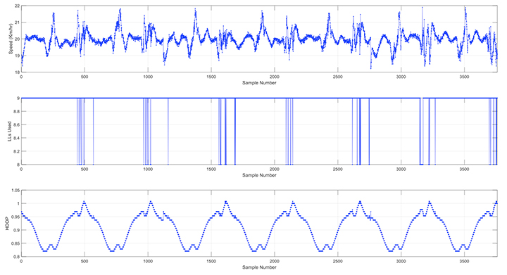
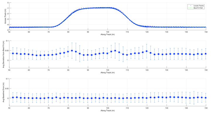
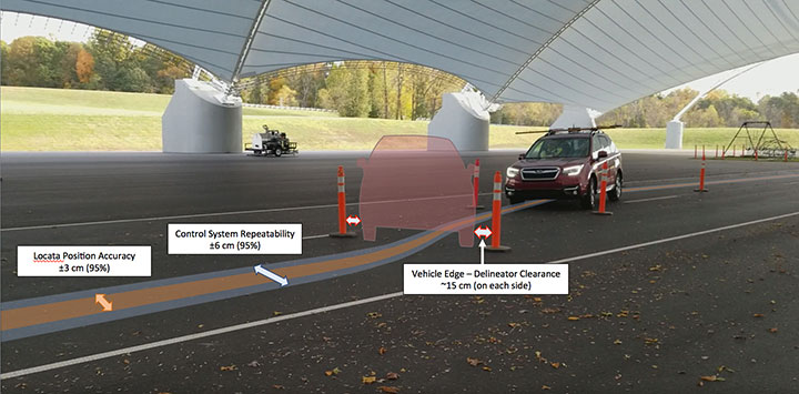
  • Safety testing in indoor and challenged environments

    Safety testing in indoor and challenged environments

    A GPS-like ground-based technology teamed with inertial measurement and driving robots to deliver the necessary accuracy when obstructions knocked out GPS as a reliable sole sensor.

    By David Aylor, Insurance Institute for Highway Safety
    Andrew Pick, Anthony Best Dynamics Ltd.
    Paris Austin and Martin Parry, Oxford Technical Solutions Ltd.

    Consumer information organizations like the Insurance Institute for Highway Safety (IIHS) design test procedures to compare different automobile manufacturers’ safety systems. The test equipment must be repeatable and as independent as possible of time of day, weather conditions or test-driver behavior.

    In 2015 IIHS completed a $30 million expansion of the Vehicle Research Center (VRC), its centerpiece a 5-acre fabric-covered track, to allow testing to continue rain or shine. It is complemented by an outdoor track for a total area of 15 acres.

    IIHS rates crash prevention systems such as Forward Collision Warning (FCW) and Automatic Emergency Braking (AEB), and looks at how well those systems can identify road users like pedestrians and bicyclists.

    To simulate real-life potential crashes for safe, accurate and repeatable testing, the Institute has been researching robotic equipment to automate some of the driving tasks.

    While the covered track offered much needed all-weather testing capability, it introduced a challenge for the standard high-accuracy GPS/GNSS equipment used for testing. IIHS operates a multi-frequency GNSS base station with real-time corrections. High-accuracy position, velocity and time (PVT) and other relevant parameters from these GPS units are required for testing and are essential for operating robotic test equipment.

    However, tests on the covered track clearly showed the equipment was not delivering the required accuracy, reliability and repeatability: the steel trusses of the covered track roof were a sufficient obstruction to GNSS signals.

    Locata. Locata provides an RTK GPS-like positioning capability utilizing ground-based transmitters which precisely time-synchronize to one another using their proprietary ranging signals without the need for cables or atomic clocks. This delivers centimeter-level accuracy with very high reliability, in networks of strategically placed, static LocataLites (LLs).

    The IIHS Locata network was deployed with 16 LLs covering both open and covered test tracks (Figure 1). The network meets two key requirements: accuracy of 10 cm or better at 95% confidence and a very high degree of repeatability with a service availability (defined as meeting the above requirement) of better than 95% of the time.

    FIGURE 1. VRC Locata Network and HDOP Quality in Locata Service Area. (Figure: D. Aylor, A. Pick, P. Austin and M. Parry)
    FIGURE 1. VRC Locata Network and HDOP Quality in Locata Service Area. (Figure: D. Aylor, A. Pick, P. Austin and M. Parry)

    AB Dynamics. Anthony Best Dynamics supplies driving robots for the design, development and testing of automotive technology. Driving robots precisely and accurately control the vehicle steering wheel, brake and throttle pedals with a level of repeatability that vastly exceeds that achieved by human test drivers. When coupled with an accurate position measurement sensor the possibility of centimeter accurate path-following control becomes reality.

    In ABD path-following control software, motion data is collected from a Locata/INS integration unit at 100 Hz and fed back to the robot’s path-following controller. The path-following controller employs a speed-dependent look-ahead algorithm that not only maintains the vehicle heading but allows centimeter-accurate path control.

    OxTS. Oxford Technical Solutions specializes in the design and manufacture of GNSS-aided inertial navigation systems (GNSS/INS) for automotive testing.As well as one-centimeter position accuracy, OxTS systems measure movement in all vehicle-axes at up to 250 Hz.

    Systems that only rely on inertial measurements are also prone to drift with time, so OxTS products are GNSS-aided; several other inputs can be used alongside the inertial measurement platform to create a hybrid system where each technology mitigates weaknesses in others.

    The Locata network and associated receivers are configured to use the same time and coordinate frame as GPS so the measurements are identical to that of a GPS receiver. The OxTS system then uses this information as it would normally and is able to output accurate and reliable vehicle measurements while maintaining excellent position accuracy.

    Measurements can be utilized by other equipment such as driving robots or logged for post-processing. Raw measurements are also logged internally so the data can be downloaded and reprocessed post-test, to test different scenarios or make other changes.

    The driving robots have steering and pedal actuators that can be quickly installed without the need to make modifications to the vehicle as shown in Figure 2. Even with the robots installed, the steering wheel, throttle and brakes remain accessible to a human driver. At the heart of the robot is a dedicated real-time controller, which coordinates the steering and pedal robots and captures data at 1000 Hz.

    FIGURE 2. Driving robot. (Figure: D. Aylor, A. Pick, P. Austin and M. Parry)
    FIGURE 2. Driving robot. (Figure: D. Aylor, A. Pick, P. Austin and M. Parry)

    Locata and OxTS units were installed in a rear passenger seat. The Locata antenna was roof-rack-mounted on a ground plane, approximately aligned with the centerline of the vehicle. The roof rack contained a second Locata antenna connected to a second Locata receiver. This was used for post-processing accuracy analysis of the fixed baseline (distance) between the two Locata antennas.

    Test procedure

    The automation kit enables the vehicle to be driven in manual mode and record scenarios for later replay. Drive scenarios can also be created in the user interface using basic geometric shapes and designate start, end or special maneuvering points within drives.

    A local two-dimensional coordinate frame can be created with or without alignment to a global coordinate system. Each scenario may be replayed at various speed settings. For instance, most scenarios described later were replayed multiple times at different speed settings, often incrementing in fixed steps from a low speed such as 10 Km/hr.

    The demonstration platform was driven in various driving patterns on both test tracks. Figure 3 shows these patterns as a map derived from reported vehicle positions during the repeats of each scenario.

    FIGURE 3. Test Scenarios.(Figure: D. Aylor, A. Pick, P. Austin and M. Parry)
    FIGURE 3. Test Scenarios.(Figure: D. Aylor, A. Pick, P. Austin and M. Parry)

    The Double Lane Changes (DLCs) conducted on both tracks resemble the driving pattern needed for testing most collision-avoidance and lane-change features. The S-curve is a driving pattern used for the IIHS headlight evaluations.

    Analysis and results

    Data analysis was focused on characterizing the accuracy and repeatability of the automated test setup as a complete system first and then Locata alone as the core positioning system. As the first step, data from two full days of testing were reduced to repetitions of the various driving patterns shown in Figure 3. Start and end times of each repetition were extracted from AB Dynamics systems and corresponding Locata system data was further processed to generate the results shown here.

    The foundation for highly repeatable control system and positioning accuracy is to have a highly reliable network that delivers repeatable DOPs and number of ranging signals at any given track location. Repeatability of the numbers of LLs seen and the HDOPs were investigated for this purpose. Shown in Figure 4 is the actual number of LLs observed and the resulting HDOP during the five repeats of the DLCs done at 45 km/h in the covered track.

    FIGURE 4. HDOP & LL Count in Double Lane Change at 45 km/h (Covered Track). (Figure: D. Aylor, A. Pick, P. Austin and M. Parry)
    FIGURE 4. HDOP & LL Count in Double Lane Change at 45 km/h (Covered Track). (Figure: D. Aylor, A. Pick, P. Austin and M. Parry)

    The number of LLs used remain constant at seven as expected and the HDOP change resulting from the motion repeats for each of the repetitions. Shown in Figure 5 are similar plots for the seven repetitions of the Lap scenario done at 20 km/h in the open track. In these, the LLs used vary between 8 and 9, with the drop happening at one end of the lap. Although slight variations can be seen in the times of the drops due to the varying speed of the vehicle during the turns, the HDOP pattern repeats consistently for all seven repetitions.

    FIGURE 5. HDOP & LL Count in Lap at 20 km/h (Open Track). (Figure: D. Aylor, A. Pick, P. Austin and M. Parry)
    FIGURE 5. HDOP & LL Count in Lap at 20 km/h (Open Track). (Figure: D. Aylor, A. Pick, P. Austin and M. Parry)

    Analysis of the 48 DLC repetitions from the covered track is presented in Figure 6. Locata position data from all repetitions were averaged along the drive path to estimate a best fit path and the deviation from this was estimated (top subplot). The best fit path allows the estimation of the run-to-run deviation of the vehicle path. The middle subplot shows the mean and standard deviation of cross track error (or spread) of all the repetitions compared to the best fit path.

    FIGURE 6. Covered Track Double Lane Change Performance Statistics. (Figure: D. Aylor, A. Pick, P. Austin and M. Parry)
    FIGURE 6. Covered Track Double Lane Change Performance Statistics. (Figure: D. Aylor, A. Pick, P. Austin and M. Parry)

    Despite the 48 DLC repetitions being carried out across a range of speeds (10-45 km/h) a high level of repeatability was measured. In straight segments the control system was able to repeat all the runs with below 4 cm of mean deviation from each other. This increases to 5 cm during turns due to the increasing lateral acceleration at higher speeds. The standard deviation also follows the same pattern, remaining below 3 cm during the straight-line segments and increasing up to 5 cm during the turns. The bottom plot shows the mean and standard deviation of the baseline error measured between the two Locata antennas on the vehicle.

    Locata baseline error from repetitions of all scenarios were then used to estimate a probability distribution function (PDF) to assess the Locata positioning system performance alone. This included close to 180,000 data points from around 5 hours of automated driving in various parts of the IIHS tracks. Resulting PDF is shown in Figure 7.

    FIGURE 7. [Brown] Locata position accuracy ±3 cm (95%) using the fixed baseline between two independently operating antenna-receiver pairs in the vehicle (5 hrs of automated driving on both tracks). [Blue] ABD system repeatability ±6 cm (95%) using across track error from 48 repetitions of the Double Lane Change maneuver on the Covered Track. (Figure: D. Aylor, A. Pick, P. Austin and M. Parry)
    FIGURE 7. [Brown] Locata position accuracy ±3 cm (95%) using the fixed baseline between two independently operating antenna-receiver pairs in the vehicle (5 hrs of automated driving on both tracks). [Blue] ABD system repeatability ±6 cm (95%) using across track error from 48 repetitions of the Double Lane Change maneuver on the Covered Track. (Figure: D. Aylor, A. Pick, P. Austin and M. Parry)
    This baseline error PDF gives a positioning accuracy of ±3 cm at 95% for the Locata position system, exceeding the IIHS requirement for positioning of 10 cm at 95% (Figure 8). The control system repeatability itself shows ±6 cm at 95%, better than IIHS expectation for positioning system alone.

    FIGURE 8. Covered track automated double-lane change (DLC) test. Fully automated path following with two back-to-back lane changes through traffic delineators set 15 cm from the sides of the vehicle. Drop-in control system repeatability of ±6 cm (95%) achieved using Locata positioning accuracy of ±3 cm (95%) through 48 repetitions at speeds ranging from 10 to 45 km/hr. (Figure: D. Aylor, A. Pick, P. Austin and M. Parry)
    FIGURE 8. Covered track automated double-lane change (DLC) test. Fully automated path following with two back-to-back lane changes through traffic delineators set 15 cm from the sides of the vehicle. Drop-in control system repeatability of ±6 cm (95%) achieved using Locata positioning accuracy of ±3 cm (95%) through 48 repetitions at speeds ranging from 10 to 45 km/hr. (Figure: D. Aylor, A. Pick, P. Austin and M. Parry)

    Conclusion

    The IIHS, one of two organizations in the United States that issue public crash safety ratings, is using Locata, a GPS-like local positioning system, under a canopy-covered test track that doesn’t have RTK-capable GNSS signal visibility.

    Precise positioning from Locata integrated with INS by OxTS demonstrates automated path following with centimeter-level repeatability using driving robots from AB Dynamics. The authors thank and acknowledge the Locata team for the excellent support provided throughout the project.