Tag: Triumph LS

  • Case studies reveal survey tech advances

    Case studies reveal survey tech advances

    The creed “Neither snow nor rain nor heat” may apply to postal workers, but it also could apply to land surveyors.

    Today’s surveyors rely on GNSS as a critical tool to enable completion of their tasks, whether defining a property boundary or mapping mining drill sites.

    In the articles that follow, surveyors share their success stories using the latest GNSS receivers, software and correction services, all of which are constantly improving to make their tasks easier — despite the terrain or weather conditions.


    How one man triumphs

    Adam Plumley is a one-man surveying shop in North Carolina. He also wears another hat as a sales, support and product development consultant to Javad GNSS.

    “As a land surveyor, I use the equipment every day,” Plumley said. “Javad’s equipment has made it possible for me to operate solo.”

    Photo: Stephen Drake
    Photo: Stephen Drake

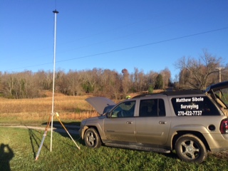
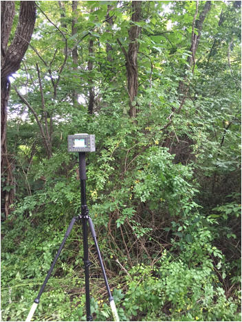
    In the project pictured above, Plumley surveyed a 50-acre farm parcel to separate out the six-acre improved northeast corner. “I located the creek, building and improvements on the property east of the road and ran the lines to the creek on the west side of the road.”

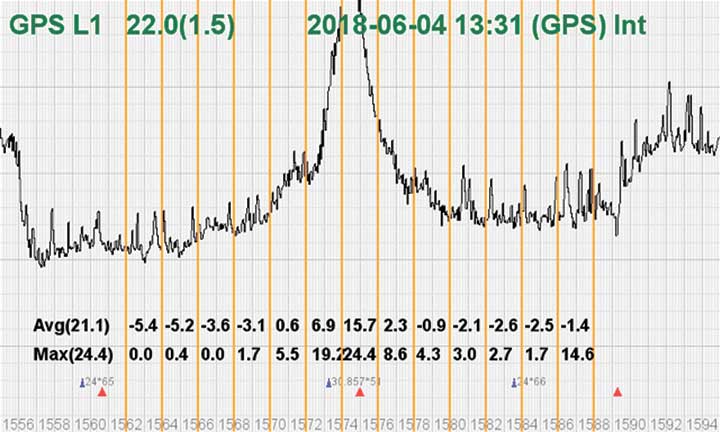
    The difficult locations on this 2016 survey were at the creeks. It took Plumley up to a half hour to locate the corners and creek points under the tree canopy.

    “It would have taken much longer than it did if I had traversed the boundary conventionally,” he said, “not to mention I would have been much more tired at the end of the day.”

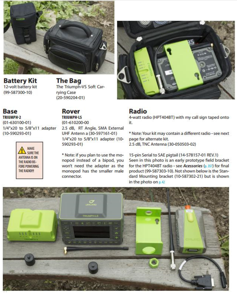
    Instead, Plumley used a Javad GNSS Triumph LS and Triumph 2 base/rover system with corrections broadcast over the internet.

    “I set up the Triumph 2 base about one mile away in an open yard with great sky view. It took me one day to do the initial recon and locations, and another couple of hours to set the new corners the next day,” he said.

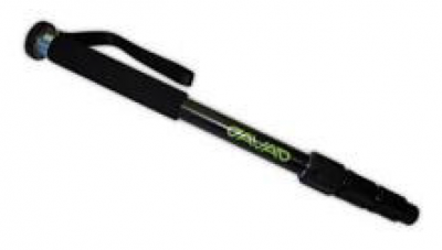
    Plumley has since upgraded his base receiver to another Triumph LS and added a J-Link 35-watt external radio to his toolbox.

    “One thing this and other challenging surveys have taught me is to be patient. To obtain accurate results that you can be confident in takes time.”
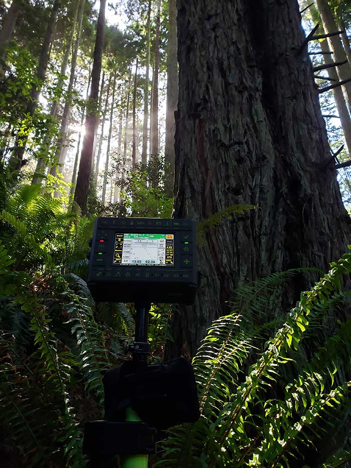
    About our cover

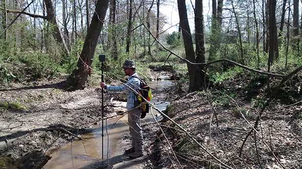
    Our cover photo this month was taken in June 2019 by surveyor Stephen Drake, near his home on the north coast of California. “These redwood forests and very rugged, remote coastal mountains can really test you,” he said. He was using his Javad Triumph-LS rover with the J-Field built-in surveying software, communicating to a Javad GNSS Triumph-2 base station attached to his house. A Verizon Jetpac mobile hotspot (in the black pack hanging below the Triumph-LS in the photo) picks up signals from his home router; the port-forwarded corrections are configured with Javad software.

    Stephen calls this his standard configuration, but finds it very flexible. When he is more than 20 miles from home base, he relies on a Triumph-2 and a radio modem placed near the site. He can also use the California Real Time Network (CRTN) with the Jetpac.

    He also relies on Javad’s Hybrid RTK, automated post-processing with Javad’s DPOS, automatically generated raw data and quality reports, and the many built-in indicators in J-Field that provide real-time feedback and “give me assurance on almost every measurement before I walk away from it,” he said.

    The efficiency that his equipment provides has made Stephen valuable even to firms that already have in-house surveyors, he said. “I honestly do not think I would be here without Javad. It has been a true potent business partner.”

    Read about another one of Stephen’s projects here.


    Check out more surveying case studies here.


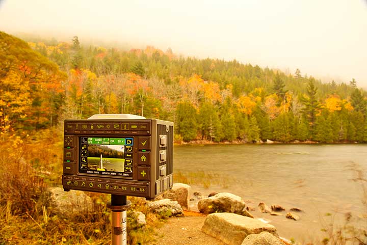
    Feature image: AP Surveying PLLC

  • J-Shield filters out interference

    J-Shield filters out interference

    The Triumph-LS receiver. (Photo: JAVAD GNSS)
    The Triumph-LS receiver. (Photo: JAVAD GNSS)

    J-Shield is a robust filter on Javad GNSS antennas that blocks out-of-band interference (Figure 1). In particular, J-Shield blocks signals that are near the GNSS bands, including the proposed Ligado Networks (formerly LightSquared) broadband signals, explained Javad Ashjaee, founder and CEO of Javad GNSS.

    FIGURE 1. Protection characteristics: The J-Shield filters have a sharp 10-dB/KHz skirt, which provides up to 100-dB of protection. (Image: JAVAD GNSS)
    FIGURE 1. Protection characteristics: The J-Shield filters have a sharp 10-dB/KHz skirt, which provides up to 100-dB of protection. (Image: JAVAD GNSS)

    The anti-jam digital filters protect against in-band interference such as the harmonics of nearby TV and radio stations, or against illegitimate in-band transmissions. The anti-jam filters can be combined in pairs for complex signal processing and can simultaneously suppress several interference signals.

    “The filters make the near band spectrums available for other uses,” Ashjaee said. “They protect GNSS bands now and in the future.”

    In-Band Noise Measurement. The receiver measures the level of interference as a percentage of noise above the normal condition. Figure 2 shows the condition in a clean environment, where eight GPS satellites were visible, according to the almanac. In all, eight C/A, six P1, six P2, six L2C and two L5 GPS signals were tracked. The noise level was 2% on C/A and L5 and 0% on P1, P2, and L2C.

    FIGURE 2. Clean environment. (Image: JAVAD GNSS)
    FIGURE 2. Clean environment. (Image: JAVAD GNSS)

    Figure 3 shows 290% noise in the GPS C/A signal and 121% noise in Galileo E1. Only one of the eight GPS C/A code and none of five Galileo E1 signals could be tracked because of the high level of interference.

    FIGURE 3. High interference levels. (Image: JAVAD GNSS)
    FIGURE 3. High interference levels. (Image: JAVAD GNSS)

    Spectrum Analyzer

    Filters in the GNSS antenna provide one way to protect GNSS signals from interference. Another is the receiver chip itself. For instance, the Javad GNSS Triumph chip includes an integrated spectrum analyzer — a more efficient solution than using a commercial spectrum analyzer to continuously monitor and evaluate the environment, Ashjaee explained.

    The spectrum analyzer monitors the spectrum inside the chip. It has an effective bandwidth of 1 KHz, and can be programmed to automatically record the spectrum (and other information) periodically or according to pre-set conditions. Each spectrum shows the power and shape of any interfering signals and jammers.

    Figure 4 shows the shape of the GPS L1 band spectrum when the band is jammed, as indicated by the huge peak in the center where the C/A code is. The number on the bottom left is the height of the peak. The height of the spectrum is 21.1 dB; compared to a calm spectrum of 11.2 dB, this spectrum indicates a jamming impact of about 10 dB.

    FIGURE 4. The L1 band is jammed, as shown by the peak.
    FIGURE 4. The L1 band is jammed, as shown by the peak. (Image: JAVAD GNSS)

    Automatic Gain Control. In addition to monitoring the spectrum, the Triumph chip also keeps a record of automatic gain control (AGC) — another indicator of unwanted external signals. The AGC monitors the environment and adjusts the gain to keep the voltage at a certain level. The change in AGC is an indicator of interference.

    Spoofers

    “Spoofers are quite different from jammers,” Ashjaee said. “They don’t disturb the environment and the spectrum shape. They broadcast a GNSS-like signal to fool the GNSS receivers to calculate wrong positions. We detect spoofers by digital signal processing.”

    With 864 channels and about 130,000 fast-acquisition channels in the Triumph 2 chip, it has the resources to assign more than one channel to each satellite to find all of the signals transmitted with the same GNSS PRN code — including spoofed signals.
    “If we detect more than one reasonable and consistent correlation peak for any PRN code, we know that we are being spoofed and can identify the spoofer signals,” Ashjaee said. The chip isolates and ignores the wrong peak.

    “Usually more than 100 signals are available at any given time. We need only four good signals to compute position,” Ashjaee said. “We reject infected signals, and then among all the available GPS, GLONASS, Galileo, BeiDou, IRNSS and QZSS signals, we use the healthy ones. It is extremely unlikely that we can be spoofed without our knowledge. We can immediately recognize spoofing and take corrective actions. In the rare case that all signals are affected, we inform the user and guide them to use a compass and altimeter to get out of the jammed area.”

    Figure 5 is a screenshot from the company’s Triumph-LS survey receiver, showing the details of each signal tracked. The first six lines in this screenshot show the spoofed signals that were detected as soon as they appeared (number “1” in the C1 column). Percentages show the amount of interference above the normal level.

    In the last column, T indicates the signal was tracked by the main channels, Q by the fast-acquisition channels, and U indicates the signal was used in position calculations.

    Figure 5. Signal Details: The Triumph-LS receiver provides users with a wealth of information on each signal received, including spoofed signals.
    Figure 5. Signal Details: The Triumph-LS receiver provides users with a wealth of information on each signal received, including spoofed signals.

    Indicators for Healthy Signals

    In addition to the spectrum shape and AGC, these other indicators show the health of GNSS signals:

    • Number of signals tracked.
    • Divergence of SNR from its expected value.
    • Level of additional power and its RMS.
    • Divergence of AGC from its normal value and its RMS.
    • Extra noise.
    • Number of signals spoofed.

    As an aid to users, the company’s Triumph-LS receiver can display the status of all GNSS signals received. Figure 6 shows this compact view, with normalized values of the above indicators (0 means good and 9 means poor).

    Figure 6. Signal Status. Information on all GNSS signals received as shown by the Triumph-LS. (Image: JAVAD GNSS)
    Figure 6. Signal Status. Information on all GNSS signals received as shown by the Triumph-LS. (Image: JAVAD GNSS)

    Users of the Triumph-LS can click on any of the signal buttons to see the actual and normalized values of the indicators for that signal. Action buttons provide quick access to View Satellites, View Spoofing, View Spectrum and Take Spectrum. Jamming and spoofing protection is an option on all Javad GNSS products and OEM boards.


    See also:

    Access denied: Anti-jam technology mitigates navigation warfare threats, By Matteo Luccio
    New CRPA concept antenna designed, By Tony Murfin

  • Spoofing detection available on Javad GNSS OEM boards

    Two methods of spoofer detection, the identification and sourcing of false GNSS signals, have been released by Javad GNSS, using features available for all of its OEM GNSS boards.

    • Spoofer detection and alarm. This feature then identifies and isolates the spoofer signal, ignores it, and provides a position solution using only valid satellite signals.
    • Determination of the direction from which the spoofing signals emanate. This can aid in tracking down the actual spoofing source.

    Spoofer Detection

    With 864 channels and roughly 130,000 quick-acquisition correlators, the Javad GNSS Triumph chip can assign more than one channel to each GNSS satellite, in order to find all the signals that are transmitted with that satellite’s PRN code. If the chip detects more than one reasonable and consistent correlation peak for any PRN code, it concludes that spoofing is present and can the proceed to identify the spoofed signals.

    In this case, it uses the position solution provided by all other clean signals (L1, L2, L5, and so on, from all GNSS constellations — GPS, GLONASS, Galileo, Beidou, and mroe) to identify the spoofer signal and use the real satellite measurement. If all GNSS signals are spoofed or jammed, then the system issues an alarm, directing the user to ignore GNSS and use other sensors in an integrated system.

    Satellite and Spoofer Peaks

    The figure below shows an example of a spoofer signal and a real satellite signal received at a GNSS receiver. These  screenshots  are from a real spoofer in a large city. The bold numbers are for the detected peaks. The gray numbers represent highest noise, not a consistent peak. A “*” symbol next to the CNT numbers indicate that signal is used in position calculation. Each CNT count represent about 5 seconds of continuous peak tracking.

    The first screenshot shows no spoofing is present. The second shows that all GPS satellites are being spoofed.

    No spoofer. Only one reasonable peak for each satellite. (Table: Javad GNSS)
    No spoofer. Only one reasonable peak for each satellite. (Table: Javad GNSS)
    Table: Javad GNSS
    Table: Javad GNSS

    In the above screenshot all GPS satellites have two peaks and all are spoofed. We were able to distinguish the spoofer signal and use the real satellite signals in correct position calculation as indicated by the ”*” next to the CNT numbers.

    GNSS Overall View

    The following screenshot  shows the status of all GNSS signals. The format and the signal definitions are explained below.

    Table: Javad GNSS
    Table: Javad GNSS

    Tracked: Tracked by the tracking channels and has one valid peak only.
    Used: Used in position calculation.
    Spoofed: Has two peaks. Good peak is isolated, if existed.
    Blocked: Blocked by buildings or by jamming. If jammed, shows higher noise level.
    Faked: Satellite should not be visible, or such PRN does not exist.
    Replaced: Real signal is jammed and a spoofed signal put on top of it. Because of jammer, it shows higher noise level.

    For determination of the direction from which the spoofing signals emanate, see Where is that spoofed signal coming from?

  • Where is that spoofed signal coming from?

    An experiment in an anechoic chamber with a JAVAD GNSS TRIUMPH-LS shows the approximate orientation of the spoofer (at 283° azimuth.)

    Javad GNSS advises that with its equipment it is possible, when a spoofer is detected in the area, to identify the direction from which the spoofing signals are coming.

    Hold the receiver antenna horizontally and rotate it slowly (one rotation in 30 seconds) to determine the angle at which satellite energies become minimum.

    The spoofer’s direction lies behind the null point of the antenna reception pattern.

    An experiment in an anechoic chamber with a Javad GNSS Triumph-LS shows the approximate orientation of the spoofer (at 283 degree azimuth.)

  • Adjusting RTK base station coordinates with the JAVAD TRIUMPH-LS

    Adjusting RTK base station coordinates with the JAVAD TRIUMPH-LS

    By Matt Johnson

    When a GNSS RTK base station is started by assuming an autonomous position, it is necessary and good practice to later adjust and correct the coordinates with a solution referenced from known coordinates. JAVAD’s field software for the TRIUMPH-LS, J-Field, has the ability to adjust the RTK base station coordinates and RTK points surveyed using corrections from that base station.

    Three methods can be used to accomplish this.

    Manually Entering New Base Station Coordinates

    Base station coordinates can be updated manually by entering new coordinates for the base station. These new coordinates can obtained through post-processing the base station data with OPUS or JAVAD’s DPOS web interface. Follow these steps to apply the corrected coordinate to the base station and adjust all the points from this base station through J-Field:

    1. Select an RTK or base station point in the Points screen.
    2. Tap on the blue screen displayed on the right side of this screen to view the Base Rover Statistics screen.
    3. Tap the Base button and you will be prompted to enter the corrected coordinates for the base station.
    4. Enter the new coordinates and tap OK.

    J-Field will then search for all the points contained in the current project with the same original matching base station coordinates and apply offsets to adjust all these coordinates into the known coordinate system. The adjusted coordinates along with the original base station and surveyed origin coordinates will still remain stored in the database for documentation purposes and so that adjustments can be undone or modified if necessary.

    Base rover statistics screen.
    Base Rover Statistics screen.

    DPOS

    When a Javad base station is started with J-Field using Base/Rover Setup, the raw GNSS data is automatically saved in the base station receiver. When the base station is then stopped with Base/Rover Setup, the data is downloaded into J-Field so that it will be available for post processing DPOS. To post-process the data, open the DPOS tool found in the CoGo menu and select the base file you wish to process. With the TRIUMPH-LS connected to the Internet, tap the DPOS button to upload the file to DPOS. This automated process will then update the base station and RTK surveyed points using the same algorithm described above.

    Shift Mode

    The newest feature of J-Field, Shift Mode, allows real-time corrections to be applied to receive base station corrections. A base station can be started with an autonomous position and then corrected by surveying a point with known coordinates. The known point could be a point previously surveyed with a base station setup in a different location. This feature is useful for several scenarios:

    • You need to move or “leapfrog” your base station to extend the radio range into a new area.
    • Your original base station point has been lost.
    • You wish to save time by starting the base station with it mounted to the top of your vehicle. Setting the base station and radio up on the top of vehicle by mounting it a roof rack or using a magnet mount saves time by eliminating the need to set up tripods and can help protect the base station from disturbances or theft in undesirable locations. For the best performance, the base station should be mounted in a level position so that phase center variations and antenna offsets are correctly applied. If you are parked on a sloped surface, it may be necessary to use a tribrach to level the receiver on the top of your car.

    The Real-time Position Shift function can be accessed from the Setup menu under Advanced. In this screen, select a point you have collected RTK coordinates from with an autonomous base station, and then the known coordinates of this point. Check the Apply Shift and the shift will be applied to all the RTK surveyed points found in the current project collected from this base station. This shift will continue to be applied to all the points surveyed from this base station.

    Position shift screen.
    Position Shift screen.

    Real-time Position Shift can also be accessed from the Collect Action screen by clicking the button below the Start button and changing the collection mode to Shift. In this mode, select the Known Point and then press Start from the action screen so that the offset can be calculated. After it has been calculated, you can apply the shift.

    Position Shift screen from the Collect Action screen.
    Position Shift screen from the Collect Action screen.
    The Collect Action screen in shift collection mode displaying the Accept/Reject Prompt for the shift.
    The Collect Action screen in shift collection mode displaying the Accept/Reject Prompt for the shift.
  • Using Reverse-Shift in J-Field

    By Matt Sibole

    One of the newest developments in J-Field, JAVAD GNSS’s onboard data collection software, is the Reverse-Shift. This feature will allow you to mount a base on a magnetic mount to the top of your vehicle, instead of putting your base on a tripod.

    This is a good idea for several reasons. First, you won’t have to worry about your tripod sinking in hot asphalt. Second, you will not have to worry about your tripod fading on frozen ground that begins to thaw.

    Figure 1. My TRIUMPH 2 base mounted above my driver-side door on the roof, with my 35-watt radio and antenna just to the left.
    Figure 1. My TRIUMPH 2 base mounted above my driver-side door on the roof, with my 35-watt radio and antenna just to the left.

    The way Reverse-Shift works is by starting your base on an autonomous position. Once your base has started transmitting, you can then go into your collect screen and change the point tab to shift. You then have the ability to select a known point (a previously surveyed or calculated point). After you have selected this known point, you can go and survey that known point.

    Figure 2. The shift screen showing the known point (previously surveyed point).
    Figure 2. The shift screen showing the known point (previously surveyed point).

    When you hit OK as shown in Figure 2, this will take you back to the collect screen, and then it will allow you to survey that point. It will give you an warning screen that states, “You are in Base Shift Calculation Mode, Do you wish to continue?” You will then be able to collect a surveyed point on the previously surveyed or calculated point. It will then give you the position shift information.

    Figure 3. The adjustment parameters for the base.
    Figure 3. The adjustment parameters for the base.

    Hit Accept, and this will adjust your base position by the stated difference, allowing you to continue to work on the known coordinate system without setting your base on a known point.

    Figure 4. Staking back out to the (known point) after the Reverse-Shift has been completed. Notice the DTT (Distance To Target) is 0.006. degrees.
    Figure 4. Staking back out to the (known point) after the Reverse-Shift has been completed. Notice the DTT (Distance To Target) is 0.006. degrees.

    At the end of the day, when you go back to your base, hit “Stop Base”. This will download the static data out of your base into your TRIUMPH-LS rover.

    The next morning when the CORS data has been uploaded, you can then post-process your base data using DPOS (JAVAD’s Data Processing Online Service). With DPOS you can then adjust your base to the TRUE state plane coordinate of where your base was actually sitting. It will also adjust all surveyed points that were collected from that base position.

    For more information on JAVAD’s J-Field software, the TRIUMPH-LS or other JAVAD GNSS solutions, please feel free to visit www.javad.com, email [email protected], or call 1-888-550-5301 or 1-408-770-1770.

  • Configuring the TRIUMPH-LS to Receive 5-Hz ‘Beast Mode’ Corrections

    Configuring the TRIUMPH-LS to Receive 5-Hz ‘Beast Mode’ Corrections

    By Matt Johnson

    In a previous article titled JAVAD GNSS 5 Hz “Beast Mode” RTK Base Station Corrections Reduce the Time to Acquire a Fix by 72 Percent, the benefits of RTK base station correction rates greater than 1 Hz were discussed. This article will detail how to configure a JAVAD base station and radio to transmit 5-Hz corrections to a JAVAD TRIUMPH-LS. This process includes the following steps:

    • Update the TRIUMPH-LS firmware and software.
    • Update the Options Authorization File (OAF) of your base station.
    • Update the firmware of your UHF radio.
    • Configure the UHF radio parameters and start the base station.
    • Update the TRIUMPH-LS Firmware and Software.

    The first step is to update the TRIUMPH-LS to the latest software and firmware. Javad provides all software and firmware updates free of charge. Updates can be easily downloaded and installed when the TRIUMPH-LS is connected to the Internet through Wi-Fi or with a network LAN cable. Press the Support button found on the home screen and then choose Software Updates to search for updates. If updates are found, press Update to download and install the updates.

    Update Software screen showing that an update of J-Field is available.
    Update Software screen showing that an update of J-Field is available.

    Update the Options Authorization File (OAF) of your base station.

    The next step is to check and update the OAF of your base station. Connect your base station to your PC with a USB cable and connect to it through NetView. Navigate to the Options tab in NetView and check to see if your receiver has the “RTK mode (Hz)” option of 10.

    NetView Option tab showing the RTK mode (Hz) option has a value of 10.
    NetView Option tab showing the RTK mode (Hz) option has a value of 10.

    If you do not have this option, press the Upload “From Internet” button to update your options. JAVAD GNSS is giving this option free of charge to all users who have purchased an RTK receiver.

    Update the Firmware of Your UHF Radio.

    A recent update is needed for the UHF radios to work when a call sign is being broadcast with corrections rates faster than 1 Hz. Download the latest firmware from http://javad.com/jgnss/support/update.html and follow the instructions on this page to install this firmware. When launching ModemVU on your PC, be sure to right click on it and choose “Run as administrator”.

    Configure the UHF Radio Parameters and Start the Base Station.

    To start the base with 5-Hz corrections, the Broadcast Period must be changed to 0.2 seconds in the Base/Rover Setup. “RTCM 3.0 Min” should be chosen as the correction format. This format only broadcasts the RTCM messages needed for RTK positioning and excludes information containing signal-to-noise (CNO) and full milliseconds for code observations. A modulation must be selected that has a sufficient link rate to transmit increased data rates with 5-Hz corrections. With the Channel Bandwidth set to the FCC’s limitation 12.5 kHz, the D16QAM modulation must be used. With 2-Hz corrections (0.5 second broadcast period) D8PSK modulation can also be used.

    image005
    UHF Modem Link Rates (bps)

    Modulations with greater link rates have decreased receiver sensitivity to demodulate the signal; the downside to choosing modulations with higher link rates is that they are more subject to interference and data loss when the signal is weak. Field tests have found that D16QAM modulation decreases the working range of the radio approximately 20 percent compared to DQPSK modulation.

    Radio settings for 5-Hz corrections.
    Radio settings for 5-Hz corrections.
    image007
    Radio settings for 5-Hz corrections.

    After these settings in Base/Rover Setup have been modified, press the To Base button to apply them, and then the Start Base button to start broadcasting with the configured setup.

  • INTERGEO 2015: Features of the JAVAD TRIUMPH-LS

    Javad Ashjaee of JAVAD GNSS introduces at INTERGEO 2015 a video by Shawn Billings of Billings Surveying & Mapping who discusses the features and advantages of the JAVAD TRIUMPH-LS. INTERGEO was held Sept. 15–17 in Stuttgart, Germany.

  • INTERGEO 2015: Using the JAVAD TRIUMPH-LS Camera Offset Survey Feature

    Javad Ashjaee of JAVAD GNSS introduces at INTERGEO 2015 a video by Shawn Billings of Billings Surveying & Mapping who explores the JAVAD TRIUMPH-LS camera offset survey function in depth. INTERGEO was held Sept. 15–17 in Stuttgart, Germany.

  • Collecting Points in Difficult Environments with the JAVAD TRIUMPH-LS

    Collecting Points in Difficult Environments with the JAVAD TRIUMPH-LS

    By Matt Johnson

    Fundamental in the determination of GNSS solutions is resolving the correct number of full cycles of the carrier signal (so-called fixing ambiguities) in order to resolve the ambiguity differences between the base and the rover. Distances measured from GNSS receivers contain errors caused by inaccuracies in the satellite and receiver clocks, the satellite orbits, and by the ionosphere and troposphere. When a base station is used, these errors are nearly identical to both the rover and base station receivers when the baseline distance is short. By removing these common errors through RTK processing, centimeter-level accurate vectors can be calculated between the base station and the rover.

    Multipath, the reflection of GNSS signals from nearby objects and structures, creates its own indirect measurements from the satellites to the GNSS receiver and is the most critical source of inaccuracy in precision GNSS applications. The worst case is when the receiver doesn’t see the direct signal at all, such as when satellite is behind a building but is still receiving the signal reflected off of the nearby structure. Such indirect signals are usually strong, unhelpful and misleading.

    A TRIUMPH-LS collecting a point under tree canopy.
    A TRIUMPH-LS collecting a point under tree canopy.

    The other aspect impacting the veracity of a fixed solution is when there are weak GNSS signals. Frequently, weak signals are due to their penetration directly through tree canopy. While the TRIUMPH-LS can’t move the obstacles that are creating multipath out of the way, its sophisticated engineering is designed to handle even the weakest signals like no other system with its RTK Verification System (patent pending).

    When located in difficult environments and under tree canopy, all GNSS receivers are prone to give bad fixed solutions that may appear to be acceptable if they are not verified. Existing methods to verify GNSS solutions include “dumping” the receiver, turning it upside down to cause the RTK engines to reset, and re-observing the point at a later time.

    The TRIUMPH-LS automates these processes with its built-in software features of Verify and Validate. Verify automatically resets the RTK engines after every fixed epoch is collected in the first step of its process. Epochs are sorted by distance and placed into groups during the first step. Once a group has built up a set level of confidence, the RTK engines are allowed to collect the remaining epochs without resetting. If epochs fall too far away from the best selected group from the first step, they are rejected and the RTK engines are reset.

    Validation is the final step of the process. With this feature enabled, the RTK engines will reset one final time at the end of the observation and collect 10 additional epochs. Allowing sufficient time between the first step and the final validation step will guarantee a bad solution is not allowed to be accepted. From extensive testing of these features in the worst of multipath environments, a bad solution has yet to be accepted when the Verify and Validate features are used and 120 epochs are collected.

    After using a TRIUMPH-LS system, many land surveyors who have used other GNSS receivers in the past without preforming any type of verification are starting to realize that they may have accepted many bad fixed solutions over the years. If you are not using a receiver like the TRIUMPH-LS that has the ability to automatically reset the RTK engines and verify the results, it is essential that you manually “dump” the receiver or re-observe the point at a later time so that you don’t make this same mistake.

    More information about the TRIUMPH-LS is available at www.javad.com/jgnss.

  • Form Factor and Portability of Triumph LS: As High as Your Pole Can Reach

    By  Matt Sibole

    I follow the surveyor connect message board and have seen some general discussion of the form factor of the Javad Triumph LS. I wanted to go into a little more detail on the form factor and portability of a couple of the receivers in the Javad GNSS lineup.

    Most surveyors that have been using RTK GPS equipment have been trained to keep their rod height at 2 meters to reduce error in rod height adjustment and to be able to get above general multipath hardships. This is not required with the Javad Triumph LS. The advanced multipath reduction of the Triumph LS gives the surveyor the flexibility to have the receiver anywhere from just over 1-foot high to as high as your pole may reach. The Triumph LS comes standard with a collapsible monopod pictured here.

    Photo: Triumph LS

    With the Triumph LS being an advanced GNSS receiver and data-collection system all in one, you may ask. “But what if I have to raise the pole above an obstruction to get a shot?” The Triumph LS is equipped with an audible tone and time-delayed shot setting, an internal level, an internal compass and a flashing LED light on the bottom of the receiver that all work together to allow the surveyor to collect points on objects with the receiver high above the surveyor’s head (out of sight). The LS is also equipped with a proximity sensor that will allow you to take a shot even if you cannot reach the receiver’s screen. For instance, you are out in a swamp and you can reach out and get the pole generally level (with internal tilt compensation turned on), but you cannot reach up and start collecting the shot. Wave your hand or a lath in front of the LS, and it will start recording your shot. So no matter your height or the height of the obstructions, you can still get the shot that you need.

    The form factor of the LS, while it is much different than what we are used to using, works extremely well. The LS rover paired with a Triumph 2 base is one of the most portable systems on the market as well. The Triumph LS, Triumph 2, 4-watt external UHF radio and UHF power cable all fit into a small camera bag.

    Photo: Javad

    This is the system that I personally use on a regular basis. I find that the ability to collapse the monopod allows me to easily use both hands while riding on a four-wheeler along with the ability to easily pack up the system on the four-wheeler to set up the base in more remote locations. With nearly two years of using this system, the form factor has not once been an issue. Quite the contrary — the form factor makes it much easier to navigate dense brush and have more control over the equipment.

    For more information on Javad’s J-Field software, the Triumph LS or other Javad GNSS solutions, please feel free to visit www.javad.com, email [email protected] or call 1-888-550-5301 or 1-408-770-1770.