Grab Singapore has launched a pilot program that uses high-accuracy lane-level GPS positioning to enhance the navigation experience for its driver and delivery partners in Singapore.
The pilot — rolled out in collaboration with Oppo, Qualcomm Technologies and Swift Navigation — also marks the first deployment of high-accuracy GPS positioning on mobile phones and app integration in Southeast Asia, delivering unprecedented outdoor location accuracy for Grab’s partners.
Grab is a leading app in Southeast Asia, operating across the deliveries, mobility and digital financial services sectors. It enables location-based services in more than 800 cities in eight Southeast Asian countries: Cambodia, Indonesia, Malaysia, Myanmar, the Philippines, Singapore, Thailand and Vietnam.
As part of its ongoing efforts to enhance the GrabMaps navigation experience, Grab continually explores new technologies to help improve accuracy and reliability for its driver and delivery partners. In dense urban environments such as Singapore’s high-rise buildings, multi-level roads, and underground networks can degrade standard GPS accuracy above 20 m, complicating navigation between pick-ups and drop-offs, and reducing ETA accuracy.
By bringing together leading technology partners to create an advanced navigation system, Grab’s driver- and delivery-partners can now pinpoint their location with higher accuracy, improving navigation efficiency in GPS-challenging environments, while enabling smoother pick-ups and reduced cancellations.
The pilot taps on the individual expertise of the following partners:
OPPO, which provides its Find N5 foldable phone with dual-frequency GNSS capable of supporting the latest positioning technology.
Qualcomm Technologies, which activates the Meter-Level Positioning for Mobile featured in the Snapdragon 8 Elite Mobile Platform that powers the OPPO Find N5, enabling real-time GPS correction signals.
Swift Navigation, which provides its cloud-based Skylark Precise Positioning Service that uses advanced atmospheric modeling to correct GPS signal errors and deliver 10x greater positioning accuracy. Skylark is built on top of a network of ground reference stations operated in partnership with network operators around the world, including Singapore Land Authority (SLA). SLA operates the Singapore Satellite Positioning Reference Network (SiReNT) which provides Skylark with accurate GNSS data to enable precise positioning for last mile ride hailing and logistics in Singapore.
Together, these technologies power the pilot, with OPPO’s Find N5 foldable phone, Qualcomm Technologies’s Snapdragon 8 Elite Mobile Platform, and Swift Navigation’s Skylark working in concert to deliver precision navigation experiences.
With results of the pilot, Grab plans to extend the enhanced positioning capability to its proprietary Karta devices in the near future — broadening access to precise navigation technology and ensuring more driver and delivery partners can benefit from it over time.
The term “urban canyon” was inspired by New York’s Canyon of Heroes — a stretch of Lower Broadway where tall buildings line the streets similar to a canyoenn. These human-built canyons can confuse GNSS receivers making it hard to accurately calculate a vehicle’s position. For autonomous cars, that’s not just inconvenient — it’s a major safety issue. However, with the right technology, the automotive world can “close’” these urban canyons, explains Manuel Del Castillo, vice president of business development at Focal Point Positioning.
On open roads with a clear view of the sky, satellite navigation can be remarkably accurate. Signals from multiple GNSS constellations reach the vehicle’s receiver unimpeded, helping calculate position with impressive accuracy. However, this often isn’t the case in dense urban areas.
Tall glass buildings, narrow streets, concrete bridges and overpasses all form urban canyons — and can be a barrier to even the most sophisticated navigation systems.
The Challenge
In cities and other urban environments, there are two common challenges for GNSS performance. The first is multipath interference, which occurs when signals bounce off buildings, glass façades and even parked cars before reaching the receiver. Rather than receiving one clean signal from the satellite, the receiver gets a clean signal and several delayed copies, leading to erroneous positioning estimates.
Signal occlusion is another issue, which occurs when tall buildings and structures physically block some satellite signals from view. The signals that are actually received from that satellite are reflections. This makes it difficult for the receiver to lock onto a stable fix.
In practice, both issues can cause sudden anomalies — enough to place a car on the wrong street entirely. For drivers, this is frustrating. For autonomous systems, it’s a safety risk.
The Road to Autonomy
Urban GNSS challenges aren’t new — taxi drivers in London and New York have long experienced their navigation systems getting “lost” among the towers. However, positioning accuracy is now more important than ever as automotive technology evolves and we hand over more control to our vehicles.
Advanced driver assistance systems (ADAS) are now pushing the limits of conventional GNSS. Features such as lane-keeping, automated lane changes and intelligent speed adaptation all rely on knowing the vehicle’s exact position – not just the road it’s on, but which lane.
As we move further towards autonomous driving, the stakes will be even higher. If GNSS references are unreliable, this could cause serious errors on the road. A sudden position jump in the middle of a complex urban manoeuvre is more than inconvenient — it’s dangerous.
Closing the Canyon
If autonomous cars are to drive safely and reliably in urban environments, GNSS must evolve. The answer lies in rethinking how satellite signals are processed — and in tackling the root causes of error. Traditional receivers rely heavily on hardware-based processing, meaning they integrate new technologies at a slow pace.
To help overcome this challenge, we developed S-GNSS Auto — software that enhances GNSS receiver reliability and accuracy in autonomous vehicles. Delivered as a simple firmware upgrade, it transforms GNSS into a more powerful component of the ADAS stack in areas where traditional solutions fall short.
We recently integrated S-GNSS Auto onto STMicroelectronics’ Teseo GNSS devices, and tested the impact of the joint solution in some of the most challenging urban environments: Shinjuku in Tokyo, and Frankfurt and the Black Forest in Germany. The combined solution demonstrated an improvement in measurement accuracy by up to four times and position accuracy by up to three times in the challenging sections of these environments. By ignoring reflected or non-line-of-sight signals, S-GNSS Auto can also reject potential spoofing attacks, enhancing the security of the GNSS receiver.
McKinsey reports that 12% to 20% of cars could have advanced autonomous driving capabilities by 2030. For automakers, this means expanding the roads and environments that can safely support these capabilities. S-GNSS® Auto helps make that possible by improving GNSS reliability and laying the foundation for advanced vehicle-to-everything (V2X) and ADAS technologies needed to support autonomous vehicle safety in challenging urban areas. Working directly from the chip, it provides a cost-effective and accessible way for automotive OEMs to upgrade their technology via a firmware upgrade.
To see the impact of the integrated S-GNSS Auto and Teseo solution, download the latest data from our trials in Japan and Germany here.
This article is contributed by Focal Point Positioning.
Cohda Wireless has successfully demonstrated its connected autonomous vehicle technology in a live trial on the streets of the city of Adelaide, Australia.
The trial proved the potential for connected self-driven vehicles to make streets safer and that Cohda’s technology is effective even in challenging urban canyons.
In an area covering two city blocks east of Adelaide’s Victoria Square, the demonstration replicated a scenario that is a daily occurrence on the streets of cities all over the world.
In the scenario, two vehicles approach a four-way intersection at right angles to each other. Car 2, driven by a human, fails to adhere to the red-light signal and approaches the intersection at speed, intending to “skip” the red light. Car 1, a connected autonomous vehicle, is approaching the intersection from another direction and intends to proceed through the intersection on the green light.
In a real-life scenario, there would be a risk of a collision as human drivers will invariably approach the intersection when the light is green, fully confident that all other road users will obey the traffic signals. In an instance where Car 2 disobeyed the traffic signal and Car 1 was unable to see the approaching danger, due to visibility being obstructed by buildings or other infrastructure, a collision would be especially likely.
But as Cohda Wireless’s Chief Technical Officer Professor Paul Alexander explained, if the vehicles were connected using Cohda’s V2X (Vehicle-To-Everything) technology, a potential collision situation would be detected and avoided well in advance of it actually happening.
“We demonstrated that when vehicles are connected to each other using our smart V2X technology, Car 1, the connected autonomous vehicle, would detect that Car 2 is approaching the red light at speed and is probably not going to stop. This allows the connected autonomous vehicle to pre-emptively identify and respond to the threat by slowing down and stopping.”
“Cohda’s V2X technology allows vehicles to ‘speak to each other’ to extend their perception horizon,” added Alexander.
“The technology provides the vehicle with an awareness of its environment and risk factors associated with it, consistently and accurately up to ten times per second, enabling it to make decisions that a human being would not be capable of making as the driver of the vehicle.”
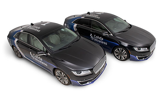
Cohda’s Smart Cars Smart City initiative was funded by the South Australian Department of Transport and Infrastructure’s Future Mobility Lab Fund. In June this year, Cohda Wireless took ownership of two specially-modified vehicles from the U.S. that it is using in advanced trials of its V2X (Vehicle-To-Everything) technology.
The two Lincoln MKZ sedans were fitted with the ADAS (Advanced Driver Assistance Systems), ROS (Robot Operating System) various sensors including lidar, radar, cameras, GPS as well as in-vehicle compute platform and Cohda’s GNSS- independent positioning technology.
The fusion and cooperation of the various sensors and Cohda’s V2X technology augment the vehicles’ perception capability and make the autonomous vehicles features more practical, to include threat detection, the dangers associated with blind intersections and vulnerable road users, the company said.
“Our goal today was not only to demonstrate the efficacy of our technology in enabling self-driven vehicles to communicate with each other, but also to do so in a city environment where so-called ‘urban canyons’ significantly affect the ability of systems reliant on Global Navigation Satellite Systems (GNSS) to achieve accurate positioning,” Alexander said.
“The area in the city of Adelaide in which the trial was conducted was one such urban canyon where positioning through GNSS can be off by up to 40 meters, but with our V2X Locate technology positioning accuracy is improved to within a meter.”
Photo: Cohda Wireless
Cohda Wireless demonstrated the efficacy and accuracy of its V2X-Locate system in a 2017 trial in New York City where it repeatedly demonstrated sub-meter accuracy while driving along Sixth Avenue, which has the tallest buildings in the Big Apple. Comparably tested GPS-based systems were as much as tens of meters off-course, at times showing cars driving through buildings.
Cohda’s V2X technology underpins and complements other technology used by autonomous vehicles such as cameras, sensors, radars and lidars by enabling cooperative perception.
“The role of technology in making our roads safer is probably not generally understood but we hope that this demonstration has helped to prove that with the appropriate technology and infrastructure, connected self-driving vehicles are safer to have on our roads than vehicles controlled entirely by human beings,” added Alexander.
Oscilloquartz has launched the OSA 5405 SyncReach, an integrated PTP grandmaster and GNSS receiver with a patent-pending dual antenna and receiver to enable the mass roll out of small cells.
The new technology has been specifically engineered to provide accurate and affordable phase synchronization for the rapidly growing small-cell market and meet the stringent timing requirements of 4.5G and 5G connectivity.
With the OSA 5405, operators can migrate from legacy GNSS RF antennas and cables to standard, cost-effective copper and fiber Ethernet cabling, reducing capital expenditure and operating expenses, Oscilloquartz said.
Available in both indoor and outdoor variants, the OSA 5405 can be deployed in challenging environments, including urban canyons where GPS signals fail. The OSA 5405’s miniscule form factor also enables it to be positioned on indoor windows to avoid multipath signal interference from objects within the building.
The OSA 5405 uses a unique dual GNSS antenna and receiver algorithm to mitigate interference from multipath signals that can affect accuracy, particularly in urban canyons, according to the company.
“We’re at the start of a new era. With the internet of things (IoT) connecting more wireless devices and 5G just around the corner, small cells will have a big role to play,” said Gil Biran, general manager at Oscilloquartz. “This market is set to grow exponentially in the next few years. Small cells will soon be everywhere and that makes precise synchronization essential. Operators urgently need a way to reliably and affordably deliver new levels of phase accuracy.
“We’ve created our OSA 5405 to effectively deliver small cell synchronization in any environment and eliminate all restrictions,” Biran said. “Our new technology radically simplifies GNSS antenna installation. The use of PTP removes the need to compensate for cable delay and extends the reach of GNSS. It enables operators to forget about archaic and expensive RF cables and use simple copper cabling or optical fiber for longer distances. And, with variants that can be positioned in almost any location, it provides strictly accurate timing precisely where it’s needed.”
The compact design and power-over-Ethernet capabilities of the indoor- or outdoor-mounted OSA 5405 enable synchronization at the edge of the mobile network. This creates dramatic reductions in complexity and power requirements as well as lower costs for installation and operation.
Another feature of the new technology is IP connectivity, so that synchronization becomes another element of the internet of things.
The OSA 5405’s highly precise GNSS-sourced synchronization is supported by network-based Sync-E and PTP backups. In high-rise buildings it can also deliver synchronization recovered from the GNSS smart receiver over optical fiber.
The ADVA FSP Network Manager with comprehensive Syncjack assurance guarantees efficient operation.
“Make no mistake; the launch of our OSA 5405 is a major milestone in the progress towards mass-scale small cell deployment,” said Nir Laufer, product line director at Oscilloquartz. “With its plug-and-play simplicity, miniscule form factor and multiple timing functions in a single device, this is a key technology for 5G networks and the IoT.
“Currently deployed in trials with major carriers, it will shortly be available to all operators looking to harness next-generation synchronization precisely where it’s needed,” Laufer said.
Long-term evolution (LTE) cellular signals can be exploited for accurate and resilient autonomous vehicle navigation in the absence of clear GNSS signals. Simulation and experimental results demonstrate that GPS-like performance can be achieved in the absence of GPS signals when cellular pseudoranges aid an inertial navigation system.
By Zaher M. Kassas, Joshua J. Morales, Kimia Shamaei, and Joe Khalife
Navigation systems onboard today’s vehicles mainly rely on integrating global navigation satellite system (GNSS) receivers with an inertial navigation system (INS). As vehicles approach full autonomy, requirements on the accuracy and resiliency of the vehicle’s navigation system become ever more stringent.
Besides the known limitations of GNSS indoors and in deep urban canyons, recent cyber attacks on GNSS signals (jamming and spoofing) are exposing an alarming vulnerability, necessitating alternative and complementary navigation systems when GNSS signals become unavailable or untrustworthy.
When GNSS signals become unavailable, the errors of the INS’s navigation solution diverge, and the divergence rate is dependent on the quality of the inertial measurement unit (IMU). Such diverging errors compromise the required safe and efficient operation of autonomous vehicles (AVs).
Two conflicting considerations arise in the design of an AV’s integrated navigation system: high accuracy and low size, weight, power and cost (SWaP- C). Current trends to supplement an autonomous vehicle’s navigation system in the inevitable event when GNSS signals become unusable are traditionally sensor-based, such as cameras and lasers.
However, such sensors could violate SWaP-C constraints and may not function properly all the time, in all weather conditions. Recently, research in navigation via signals of opportunity (SOPs) has revealed their potential as an attractive source for navigation in GNSS-challenged environments. SOPs are ambient radio signals, which are not intended as positioning, navigation and timing sources: cellular, Wi-Fi, AM/FM, digital television, Iridium satellites and so on. SOPs are practically free to use and could alleviate the need for expensive and bulky aiding sensors.
Among different SOPs, cellular signals are particularly attractive due to their inherent characteristics:
Abundance: Cellular signals base transceiver stations (BTSs) are plentiful.
Geometric diversity: The cellular system configuration by construction yields favorable BTS geometry, unlike certain terrestrial SOPs such as digital television, which tend to be co-located.
Large bandwidth: Cellular signals have a bandwidth up to 20 MHz, yielding accurate time-of-arrival (TOA) estimation.
High received power: The received carrier-to-noise ratio (C/N0) from nearby cellular BTSs is commonly tens of dBs higher when compared to GNSS signals.
While cellular SOPs are lucrative to exploit for navigation purposes, a number of challenges must be first addressed, since such signals were never intended for navigation purposes. TABLE 1 compares GNSS space vehicles (SVs) and cellular BTSs with respect to relevant navigation attributes. Unlike GNSS SVs whose positions and clock errors are transmitted to the receiver in the navigation message, cellular BTSs do not transmit such information. Therefore, the receiver must either estimate these quantities in a stand-alone fashion or have access to a database (cloud-hosted) that is crowdsourcing this information from multiple nearby receivers.
The first strategy is analogous to the simultaneous localization and mapping (SLAM) problem in robotics, while the second strategy could be achieved by deploying multiple receivers, whether vehicle-mounted or affixed on dedicated stations.
This article discusses relevant cellular code division multiple access (CDMA) and long-term evolution (LTE) signals that could be exploited for navigation. The article also presents a specialized software-defined receiver (SDR) called Multichannel Adaptive TRansceiver Information eXtractor (MATRIX), developed at the Autonomous Systems Perception, Intelligence, and Navigation (ASPIN) Laboratory at the University of California, Riverside. MATRIX is capable of producing pseudorange observables to cellular CDMA and LTE BTSs. We also present a radio SLAM approach for AV navigation via a tightly-coupled cellular-aided INS framework. Simulation and experimental results demonstrate ground vehicles and unmanned aerial vehicles (UAVs) navigating with cellular signals in the absence of GNSS signals.
CDMA SIGNALS
CDMA is at the heart of third-generation (3G) wireless communication systems, which use orthogonal and maximal-length pseudorandom noise (PN) sequences to enable multiplexing over the same channel. The sequences transmitted on the forward link channel, from BTS to receiver, are known. By correlating the received cellular CDMA signal with a locally generated PN sequence, the receiver can estimate the TOA and produce a pseudorange measurement. In a cellular CDMA communication system, 64 logical channels are multiplexed on the forward link channel: a pilot channel, a sync channel, seven paging channels, and 55 traffic channels.
The receiver uses the pilot signal to detect the presence of a CDMA signal and synchronize its locally-generated short code. The sync and paging channels are used to provide time and frame synchronization to enable the receiver to register in the network. All forward-link signals are spread at 1.2288 MHz by a 32,768-chip PN sequence called the short code. To distinguish the received data from different BTSs, each station uses a shifted version of the short code. This shift, known as the pilot offset, is unique for each sector of each BTS and is an integer multiple of 64 chips; hence, a total of 512 pilot offsets can be realized.
The goal of a cellular CDMA navigation receiver is to acquire and track the signal parameters, namely the code phase and the carrier phase. To this end, such a receiver consists of three main stages: signal acquisition, signal tracking and message decoding. The pilot channel is used for signal acquisition and tracking. In fact, the pilot channel is dataless: only the short code is transmitted. This enables longer integration periods. A search in time and frequency in the acquisition stage obtains a coarse estimate of the TOA and the Doppler frequency.
Next, these parameters are tracked and their estimates are refined via tracking loops. Similar to a GPS receiver, a phase-locked loop (PLL) and a carrier-aided delay-locked loop (DLL) are used to track the carrier and code phase, respectively. Finally, the sync and paging channels are decoded for timing and data association purposes. FIGURE 1 illustrates the three stages of the cellular CDMA module of the MATRIX SDR, implemented as LabVIEW virtual instruments (VIs), and the front panel corresponding to each stage.
LTE SIGNALS
LTE has become the prominent standard for fourth-generation (4G) communication systems. Its multiple-input, multiple-output capabilities allow higher data rates compared to previous wireless standards. The high bandwidth and ubiquity of LTE networks make LTE signals attractive for navigation. In LTE Release 9, a broadcast positioning reference signal (PRS) was introduced to enable network-based positioning capabilities within the LTE protocol.
However, PRS-based positioning suffers from a number of drawbacks:
The user’s privacy is compromised since the user’s location is revealed to the network.
Localization services are limited only to paying subscribers and from a particular cellular provider.
Ambient LTE signals transmitted by other cellular providers are not exploited.
Additional bandwidth is required to accommodate the PRS, which caused the majority of cellular providers to choose not to transmit the PRS in favor of dedicating more bandwidth for traffic channels.
To circumvent these drawbacks, user equipment-(UE)-based positioning approaches, which exploit the existing reference signals in the transmitted LTE signals, have been explored.
LTE Frame Structure. LTE uses orthogonal frequency division multiplexing (OFDM) to transmit signals. In OFDM, the transmitted symbols are first parallelized into groups of length Nr. Then, to provide a guard band, the resulting signal is zero-padded to a length Nc, which is set to be greater than Nr. Finally, an inverse fast Fourier transform (IFFT) is taken, and the last Lcp elements are repeated at the beginning. TABLE 2 shows the possible values for Nr and Nc in an LTE system.
The OFDM signals are arranged into blocks called frames. A frame is composed of 10 ms data, which is divided into either 20 slots or 10 subframes with duration of 0.5 ms or 1 ms, respectively. A slot can be decomposed into multiple resource grids and each resource grid has numerous resource blocks. Then, a resource block is broken down into the smallest elements of the frame, namely resource elements. The frequency and time indices of a resource element are called subcarrier and symbol, respectively.
LTE Reference Signals
There are three possible reference sequences in a received LTE signal that can be exploited for navigation.
Primary synchronization signal (PSS). The PSS is transmitted in symbol 7 of slots 0 and 10 of each frame. This signal, which is transmitted on the middle 62 subcarriers, provides symbol timing to the UE. The PSS is expressible in only three different orthogonal sequences, each of which represents a BTS’s (also known as eNodeB) sector ID. This presents two main drawbacks: the received signal is highly affected by interference from neighboring eNodeBs with the same PSS sequences, and the UE can only simultaneously track a maximum of three eNodeBs, which is not desirable in an environment comprising more than three eNodeBs.
Secondary synchronization signal (SSS). The SSS is transmitted in symbol 6 of slot 0 or 10 of each frame. This signal, which is transmitted on the middle 62 subcarriers, provides frame timing to the user equipment. The SSS is expressible in only 168 different sequences, each of which represents the cell group identifier; therefore, it does not suffer from the aforementioned drawbacks of the PSS. The transmission bandwidth of the SSS is 930 KHz, which is slightly less than the GPS C/A code bandwidth (1.023 MHz). Therefore, navigation with SSS provides comparable results to GPS: low-cost and relatively precise pseudorange information using conventional PLLs and DLLs in an environment without multipath, but low TOA accuracy in a multipath environment.
Cell-specific reference signal (CRS). The CRS is mainly transmitted to estimate the channel between the eNodeB and the UE. Therefore, it is scattered in both frequency and time and is transmitted from all transmitting antennas. The CRS is known to provide better accuracy in estimating the TOA in a multipath environment due to its higher transmission bandwidth. Since the CRS is scattered across the LTE bandwidth, it is not possible to track the TOA from the CRS using conventional low-complexity DLLs. Several methods can be used to estimate the channel parameters, including the TOA: multiple signal classification (MUSIC), estimation of signal parameters via rotational invariance techniques (ESPRIT) and space-alternating generalized expectation-maximization (SAGE) algorithms.
LTE Receiver Structure
The LTE navigation receiver exploits SSS, PSS and CRS, and consists of four stages.
Acquisition. In this step, the received signal is correlated with the locally generated PSS and SSS signals to obtain the frame start time estimate, Doppler frequency estimate and the eNodeB’s cell ID.
System information extraction. In LTE systems, the bandwidth can be assigned to different values. The actual value of the bandwidth is provided to the UE by the eNodeB in a block called master information block (MIB). When user equipment enters an LTE network, it starts receiving signals with the lowest possible bandwidth. After obtaining the frame start time, it is possible to convert the LTE signals into frame structure by executing the steps discussed in the LTE Frame Structure section in reverse order. Then, the UE decodes the MIB and obtains the actual bandwidth. The UE can then increase the sampling rate to as high as the signal bandwidth.
Due to the near-far effect on the PSS signal, it is not possible to acquire all the available eNodeBs in the environment. Each eNodeB provides the list of its neighboring cell IDs to the UE in the system information block (SIB). After obtaining the frame start time and the actual transmission bandwidth, the UE can decode the SIB to obtain the neighboring cell IDs.
Tracking. The receiver starts tracking the SSS using components of the tracking loop: a frequency-locked loop (FLL)-assisted PLL to track the carrier phase and a carrier-aided DLL to track the code phase.
Timing information extraction. To overcome the error due to multipath in tracking the SSS, the CRS is used. For this purpose, by knowing the CRS sequence and the received signal, the channel frequency response is first estimated. Then, the channel impulse response is obtained by taking an IFFT of the channel frequency response. Finally, the first peak of the channel impulse response is detected, which represents the line-of-sight TOA.
FIGURE 2 illustrates the block diagram of the LTE module of the MATRIX SDR and the corresponding LabVIEW VIs.
CELLULAR-AIDED INERTIAL NAVIGATION
To correct INS errors using cellular pseudoranges, an extended Kalman filter (EKF) framework similar to a traditional tightly coupled GNSS-aided INS integration strategy is adopted, with the added complexity that the cellular BTSs’ states (position and clock error states) are simultaneously estimated alongside the navigating vehicle’s states (position, velocity, attitude, IMU measurement error states and receiver clock error states). This framework is composed of two modes.
Mapping Mode. The EKF produces estimates and associated estimation error covariances of both the navigating vehicle and the cellular BTSs’ states (augmented in x) using both GNSS SV and cellular BTS pseudoranges. Between aiding corrections, the EKF produces the state prediction x^– and prediction error covariance P– using INS model and receiver and cellular BTS clocks models. When an aiding source is available, either a GNSS SV or cellular BTS pseudorange, the EKF produces a state estimate update x^+ and associated estimation error covariance P+.
SLAM Mode. The cellular-aided INS framework enters a SLAM mode when GNSS pseudoranges become unavailable. In this mode, INS errors are corrected using cellular BTS pseudoranges and the cellular BTSs’ state estimates provided from the mapping mode. As the autonomous vehicle navigates, it simultaneously continues to refine the BTSs’ state estimates. FIGURE 3 illustrates a high-level diagram of the cellular-aided INS framework.
SIMULATION RESULTS
To evaluate the performance of this cellular-aided INS framework presented, simulations were conducted of a UAV equipped with the MATRIX SDR, navigating in downtown Los Angeles, while exploiting ambient cellular signals. Two navigation systems were employed to estimate the trajectory of the UAV: a traditional tightly-coupled GPS-aided INS with a tactical-grade IMU; and the cellular-aided INS discussed here with a consumer-grade IMU.
A simulator generated the true trajectory of the UAV and clock error states of the UAV-mounted receiver, the cellular BTSs’ clock error states, noise-corrupted IMU measurements of specific force and angular rates and noise-corrupted pseudoranges to multiple cellular BTSs and GPS SVs.
The IMU signal generator models a triad gyroscope and a triad accelerometer, each with time-evolving biases that provided sampled data at 100 Hz. GPS L1 C/A pseudoranges were generated at 1 Hz using SV orbits produced from receiver independent exchange files downloaded Oct. 22, 2016, from a continuously operating reference station server. The GPS L1 C/A pseudoranges were set to be available for only the first 100 seconds of the 200-second simulation. Cellular pseudoranges were generated at 5 Hz to four BTS locations, which were surveyed from real tower positions in downtown Los Angeles.
The UAV’s true trajectory included a straight segment followed by two banked orbits in the vicinity of the four cellular BTSs, shown in FIGURE 4(a). The resulting EKF estimation errors and corresponding three standard deviation bounds for the north and east position of the UAV are plotted in FIGURE 4(b). The navigation solution from using the cellular-aided INS and navigation solution from using only an INS during the 100 seconds GPS pseudoranges were unavailable appear in FIGURE 4(c). The final BTS estimated position and corresponding 95th percentile estimation uncertainty ellipse is shown in FIGURE 4(d).
We can conclude that when GPS pseudoranges become unavailable at 100 seconds, the estimation errors associated with the traditional GPS-aided INS integration strategy begin to diverge, as expected, whereas the errors associated with the cellular-aided INS are bounded within this 100-second duration of GPS unavailability. Second, when GPS was still available during the first 100 seconds, the cellular-aided INS with a consumer-grade IMU almost always produced lower estimation error uncertainties when compared to the traditional GPS-aided INS integration strategy with a tactical-grade IMU.
EXPERIMENTAL RESULTS
To evaluate the standalone LTE navigation performance, two field tests were conducted with real LTE signals in semi-urban and urban environments. In both tests, a ground vehicle was equipped with LTE and GPS antennas and universal software radio peripherals (USRPs). LTE signals were simultaneously downmixed and synchronously sampled via a dual-channel USRP driven by a GPS-disciplined oscillator. The GPS navigation solution served as ground truth. FIGURE 5(a) shows experimental results for a CRS-based and an SSS-based receiver in a semi-urban environment with moderate multipath. The table, FIGURE 5(b), demonstrates the importance of exploiting CRS to alleviate multipath effects. Figure 5(b) shows the experimental results for a CRS-based receiver in an urban environment with severe multipath.
To evaluate the performance of cellular-aided inertial navigation, a field test was conducted with real cellular signals and an IMU-equipped UAV. The UAV was equipped with three antennas to acquire and track:
GPS signals
LTE signals from nearby eNodeBs
cellular CDMA signals from nearby BTSs.
Samples of the received signals were stored for off-line post-processing. The LTE and CDMA signals were processed by the MATRIX SDR. FIGURE 6 depicts the experimental hardware setup.
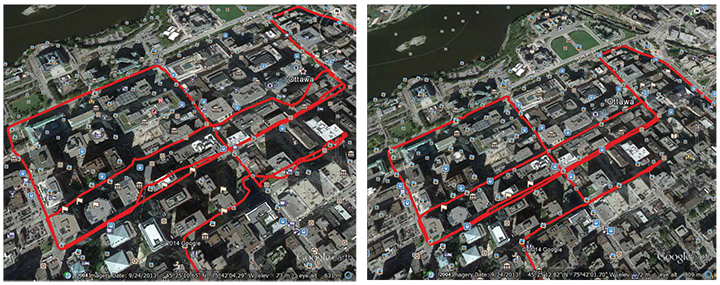
Experimental results are presented for two scenarios: the cellular-aided INS described in this article, and for comparative analysis, a traditional GPS-aided INS using the UAV’s IMU. The true trajectory traversed by the UAV is plotted in the opening figure (b)-(c), which consists of a GPS unavailability run of 50 seconds, starting at a location marked by the red arrow. The north-east root mean squared errors (RMSE) of the GPS-aided INS’s navigation solution after GPS became unavailable was more than 100 meters.
The UAV also estimated its trajectory using the cellular-aided INS framework using signals from the two eNodeBs and three cellular BTSs illustrated in opening figure (a) to aid its onboard INSs. The north-east RMSEs of the UAV’s trajectory after GPS became unavailable was 4.68 meters with a final error of 4.92 meters.
TABLE 3 summarizes the UAV’s RMSEs and final errors.
CONCLUSION
Cellular signals can be exploited to navigate in the absence of GNSS signals. Experimental results demonstrated a UAV navigating with a cellular-aided INS using two LTE eNodeBs and three cellular CDMA BTSs achieving GPS-like performance in the absence of GNSS signals. This article is based on IEEE/ION PLANS, ION GNSS+ and ION ITM papers by the authors; see online version.
This work is supported by grants from the Office Naval Research (ONR) under Grant N00014-16-1-2305 and the National Science Foundation (NSF) under Grant 1566240.
MANUFACTURERS
Cellular antennas used were consumer-grade 800/1900-MHz cellular omnidirectional antennas. The UAV and GPS antenna used were DJI with the A3 flight controller. The cellular signals were simultaneously down-mixed and synchronously sampled via two Ettus E-312 USRPs tuned to 1955 MHz (AT&T) and 882.75 MHz (Verizon) carrier frequencies.
JOSHUA J. MORALES is a Ph.D. student at the University of California, Riverside and a member of the Autonomous Systems Perception, Intelligence, and Navigation (ASPIN) laboratory.
KIMIA SHAMAEI is a Ph.D. candidate at the University of California, Riverside and a member of the ASPIN Laboratory.
JOE KHALIFE is a Ph.D. student at the University of California, Riverside and a member of the ASPIN Laboratory.
ZAHER (ZAK) M. KASSAS is an assistant professor at the University of California, Riverside and director of the ASPIN Laboratory. He received a Ph.D. in electrical and computer engineering from the University of Texas at Austin.
GPS positioning in urban scenarios is challenging because of large numbers of non-line-of-sight outlier measurements. We propose a robust positioning algorithm that combines GPS observations with visual-inertial odometry information to handle such outliers. We demonstrate the effectiveness of our algorithm in a simulation scenario with close to 80-percent outliers. In experiments in a mild urban-canyon environment, our approach reduces the 95th percentile horizontal positioning error by 66 percent compared to a GPS-only solution.
Motivation
GPS performance drastically degrades if large parts of the sky are obstructed. This occurs for example in urban-canyon scenarios, where GPS positions may be off by as much as 50 meters. These large positioning errors are prohibitive in applications such as autonomous vehicles and advanced driver assistance systems (ADAS).The large positioning errors in urban canyons are mainly caused by non-line-of-sight (NLOS) observations and multipath effects. Such observations result when the line-of-sight (LOS) path from the receiver to a satellite is blocked, and the receiver instead erroneously tracks a reflected version of the satellite signal.
Summary of Results
We propose a low-cost method to detect and remove such NLOS outliers by combining GPS pseudorange measurements with visual inertial odometry (VIO) measurements. These measurements are complementary: GPS pseudoranges provide absolute positioning information; VIO measurements, constructed from camera frames and inertial measurements, provide high-accuracy relative positioning.
We develop a robust and efficient, tightly-coupled GPS+VIO positioning algorithm, able to work under extremely challenging conditions. For example, in scenarios with close to 80 percent of GPS measurement outliers or with only intermittent satellite visibility. Even under these extreme conditions, the proposed algorithms are able to produce reliable and accurate position estimates.
Problem Setting
The overall positioning system consists of a GPS module and a VIO module. The GPS module provides raw pseudorange and Doppler range-rate measurements. The VIO module consists of a camera along with inertial sensors such as an accelerometer and a gyroscope. The output of the VIO processing engine are vectors of velocities and displacements expressed in the local camera coordinate frame.
We will not go into the details of the VIO design, rather we will use it as a black box that provides us with the velocities. The goal is to integrate the pseudorange measurements across time using the highly accurate velocities from the VIO to detect and discard the measurements corrupted by NLOS errors.
The positioning algorithm consists of two stages. In the first stage, we transform the velocities from the VIO frame of reference to the GPS frame of reference. This requires estimation of the rotation matrix relating the VIO frame and the GPS frame. Once this transformation is completed, the second stage is to perform outlier detection and to estimate the rover position.
InvenSense Inc. is making available its InvenSense Positioning Library (IPL) software, designed to provide sensor-assisted positioning in places where GNSS alone cannot provide desired accuracy. Invensense is a provider of intelligent sensor system on chip for motion and sound in consumer electronic devices.
InvenSense made the announcement at Mobile World Congress, taking place in Barcelona, Spain March 2-5.
The IPL incorporates advancements in sensor-assisted positioning algorithms that allow use of inertial sensors to improve GNSS positioning in urban areas where satellite signals are either blocked or distorted by multipath, enabling continuous location availability while driving in underground parking lots, tunnels, or walking in urban canyons. The IPL enables continuous and accurate position, velocity and orientation in challenging operating environments.
These sensor-assisted positioning algorithms have been designed to operate under normal pedestrian and driving use without restrictions on the device orientation. Supported pedestrian use includes handheld, hand swinging, in pocket, call mode and belt holster. The algorithms also allow any use within the vehicle, such as in cradle, cup holder or simply left on a seat. The software was designed in a way to maximize accuracy and minimize constraints on the user.
The IPL is designed to operate with an IMU and GNSS receiver as minimum hardware. Integration with a magnetometer, barometer, and vehicle speed sensor is also available, which provides additional heading integrity as well as height and velocity accuracy for sensor-assisted positioning.
IPL is designed for smartphones using Android, iOS, Windows and general Linux operating systems and has already started shipping commercially. The underlying navigation technology comes from years of development at Trusted Positioning Inc., which was acquired by InvenSense this past summer.
“With more consumers using their smartphones for turn-by-turn navigation on foot or in vehicle, one of the most frustrating user experience issues is losing your GPS (GNSS) signal in an unfamiliar location or being re-routed erroneously due to multipath errors,” said Ali Foughi, vice president of Marketing and Business Development at InvenSense. “With IPL technology, high-accuracy location guidance is always available and provides smartphone OEMs with a differentiated user experience and consumers with a more reliable navigation solution.”
The InvenSense Positioning Library is available immediately.
InvenSense is exhibiting in booth #D61 in Hall 7 at Mobile World Congress.
The new NEO-M8L Automotive Dead Reckoning (ADR) module by u-blox has integrated motion, direction and elevation sensors. The module integrates gyro and accelerometer with u‑blox’ GNSS platform u-blox M8 to achieve high indoor/outdoor positioning performance for road vehicle and high-accuracy navigation applications.
In addition to accessing the integrated module’s gyro and accelerometer data, accident reconstruction systems can provide the location of an accident to facilitate insurance claims even if a collision occurs in a tunnel or park house. High-end navigation devices are able to guide drivers through tunnels of several kilometers because of the accuracy of u-blox’ ADR system. Stolen vehicles can be located instantly due to continuous monitoring of sensor data and storage of location in non-volatile memory.
“Devices for usage-based insurance, stolen vehicle recovery, road pricing, fleet management, emergency services, and vehicle navigation depend on reliable, uninterrupted positioning including tunnels, park houses and stacked highways,” said Thomas Nigg, vice president of product strategy at u-blox. “The NEO-M8L is the ideal solution for all road vehicle based applications, able to calculate a position in all circumstances based on its own internal sensors, regardless of satellite visibility and end-device orientation.”
The NEO-M8L module will be demonstrated at the u-blox stand at electronica 2014 in Munich, November 11-14, Hall A4 Stand 219.
The compact module is 12.2 x 16.0 x 2.5 mm, requires minimum host integration resulting in no risk, is low cost, and provides fast time-to-market design, u-blox said. With uncritical orientation of the installed module, odometer function and autonomous data logging, it is an all-in-one solution for all road vehicle applications requiring reliable and uninterrupted position in challenging environments such as urban canyons, tunnels and underground parking.
The NEO-M8L embeds u-blox’ 3D Automotive Dead Reckoning (3D ADR) chip technology. Using the vehicle’s speed information and the module’s onboard sensors enables accurate positioning in three dimensions, even when satellite signals are completely lost and the end-device installation is not horizontal, u-blox said. An odometer function, based on the ADR technology, also provides accurate and continuous distance traveled.
The module is able to track all visible GNSS satellites including GPS, GLONASS, BeiDou, QZSS and all SBAS (European’s Galileo will be supported in a future firmware version). Concurrent reception of two GNSS systems is supported. The NEO-M8L module can output a position up to 20 times per second.
The module uses u‑blox’ M8 GNSS chip and is available in Professional Product grade. This grade includes qualification according to the ISO16750 standard “Road vehicles — Environmental conditions and testing for electrical and electronic equipment” and manufacturing in ISO/TS 16949 automotive-certified factories.
Samples and evaluation kits will be available in December 2014.
A single-feed smart antenna (left) compared to the multipath rejection results of the new TW5340 smart antenna with Accutenna technology. Photo: Tallysman
Tallysman’s new TW5340 smart antenna is designed to pair Tallysman‘s Accutenna technology antenna with STMicroelectronics’ Teseo II receiver. The combination makes the smart antenna accurate for use in all environments, including urban canyons, according to the company.
The TW5340 is a multi-constellation GNSS Smart Antenna that provides simultaneous GPS/GLONASS/SBAS reception. It is designed for use in professional-grade applications such as precision timing, network synchronization, low current applications, and tracking/positioning applications.
To illustrate the advantages of this technology coupling, simultaneous recordings of vehicle position were conducted using two smart antennas — one with and one without Tallysman’s Accutenna technology — in an area of downtown Ottawa, Canada, notorious for high levels of multipath signals. Results show how the high multipath signal rejection capabilities of Tallysman’s Accutenna technology greatly improves accuracy, the company said.
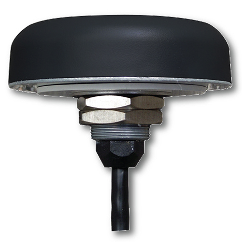
The Tallysman TW5340 smart antenna.
The TW5340 supports STMicroelectronics Autonomous A-GPS, which accelerates GPS positioning by predicting satellite ephemeris data based on previous observations. This results in extremely fast time-to-first-fix. The TW5340 can be configured to output up to three NMEA 0183 message lists with navigation update rates up to 10 Hz. RS232, CMOS, and USB interfaces are available with input voltage options of 3,3V, 5.0V, and 12V. A standby-mode feature provides for very low current consumption (<100uA) and is particularly useful in battery-operated applications.
A standard one pulse-per-second 1PPS synchronized to UTC time is available as a single ended output or as a differential output at RS422 levels.
Tallysman’s Windows-based Configurator enables simple configuration of parameters such a baud rates, output message rates, constellation, tracking parameters, 1 PPS configuration and standby-mode parameters.
The TW5340 is housed in an IP67 housing and is REACH and ROHS compliant. A non-magnetic version is also available as Part Number TW5341.
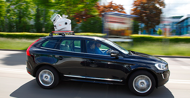
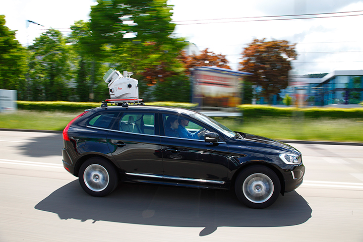
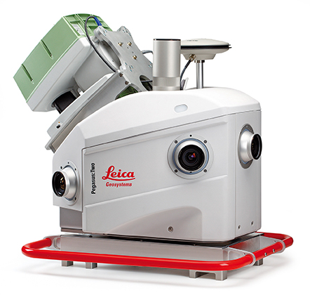
Leica Geosystems has introduced its next generation vehicle-independent mobile mapping platform, the Pegasus:Two. By calibrating imagery and LiDAR point cloud data, the Pegasus:Two delivers highly accurate and economical geospatial data in a 360° spherical view while providing two methods for extracting data — either through LiDAR or via photogrammetry.
With its enhanced sensor platform using six horizontal cameras, plus an optional rear camera and a skyward view camera, a single high-speed LiDAR sensor, and an external output for an additional sensor, the Pegasus:Two enables unlimited mobile mapping applications, from pavement analysis to geo-referencing railways systems, now possible within the same platform, the company said.
From hardware to post-processing, Pegasus:Two allows economic data collection by balancing the largest pixel to sensor ratio on the market (5.5 x 5.5 µm), delivering extremely high image resolution, in a 4-MB camera and using a single low-noise, high-speed profiler. Users can download data via Wi-Fi or wired Ethernet, or even faster by using the latest USB3 interface, by means of a multi-core, industrial PC with 1-TB storage and a solid state drive, enabling longer missions. An optional rotation mount, designed specifically for the Leica ScanStation P20, also makes mounting the terrestrial scanner upside down or right side up while also enabling left or right rotation.
The Pegasus:Two in its new streamlined housing with aerodynamic design.
Expanding on the success of Leica Geosystems’ mobile mapping software, the latest software now offers semi-automatic object extraction features, which enable easy-to-use two-click GIS metadata extraction or calculation of distances on-the-fly directly into ArcGIS for Desktop software.
Leica Geosystems also introduces an external timing output and trigger signal for use with a variety of additional sensors, from a thermal camera, to ground penetrating radar, sonar, or even a pollution monitor. The External Trigger feature synchronizes time stamping and coordinates user data with one simple click, making 3D mobile mapping very user-friendly.
Urban canyons. Equipped with the NovAtel’s ProPak6 high-precision receiver for the most demanding city or rugged environments, the Pegasus:Two offers users a truly global system. It is a future-proof investment that tracks signals of all available constellations, GPS, GLONASS, Galileo and BeiDou as well as L-band, SBAS, and QZSS band coverage to ensure the best signal even when moving through urban canyons. The system provides a low noise, 200hz Inertial Measurement Unit for tracking the vehicle path thereby ensuring data is positioned accurately.
Aerodynamic design. The Leica Pegasus:Two mobile mapping system now comes with a new streamlined and compact look and continues to fit in only two travel cases. A convenient handle surrounding the unit enables easy mounting on and off your vehicles. The Pegasus:Two is a vehicle-independent system with a rechargeable 11 hour battery, and can be used on any moving platform.
“The Leica Pegasus:Two platform is a unique complete solution,” said Stuart Woods, vice president for Leica Geosystems Geospatial Division. “By providing software and hardware designed to seamlessly work together, users not only receive the latest in mobile mapping technology but also optimal performance and faster workflows. By keeping the platform vehicle independent and adding new sensor options, we encourage our customers to find new ways, to try out different sensors, new revenue models, and new places to measure. ”
Along with the Pegasus:Two, the advanced prototype, Pegasus:T2, a trolley based mobile system weighing less than 20 kilograms will also be on display at the HxGN LIVE 2014 Conference in Las Vegas.
A new system developed by Universidad Carlos III de Madrid (UC3M) researchers uses sensors to improve the ability of GPS to determine a vehicle’s position compared to use of conventional GPS devices by up to 90 percent.
The prototype can guarantee the position of the vehicle to within 1 or 2 meters in urban settings, the researchers said.
Sensor Fusion. The prototype system incorporates a conventional GPS signal with those of other sensors (accelerometers and gyroscopes) to reduce the margin of error in establishing a location. “We have managed to improve the determination of a vehicle’s position in critical cases by between 50 and 90 percent, depending on the degree of the signals’ degradation and the time that is affecting the degradation on the GPS receiver,” said David Martín, a researcher at the Systems Intelligence Laboratory (LSI – Laboratorio de Sistemas Inteligentes) at UC3M. The system was jointly designed and developed by LSI and the Applied Artificial Intelligence Group (GIAA – Grupo de Inteligencia Aplicada Artificial).
The margin of error of a commercial GPS, such as those that are used in cars, is about 15 meters in an open field, where the receiver has wide visibility from the satellites. However, in an urban setting, the determination of a vehicle’s position can be off by more than 50 meters, due to the signals bouncing off of obstacles like buildings, trees, or narrow streets. In certain cases, such as in tunnels, communication is lost, hindering the GPS applications reaching Intelligent Transport Systems, which require a high level of security.
“Future applications that will benefit from the technology that we are currently working on will include cooperative driving, automatic maneuvers for the safety of pedestrians, autonomous vehicles or cooperative collision warning systems,” the scientists comment.
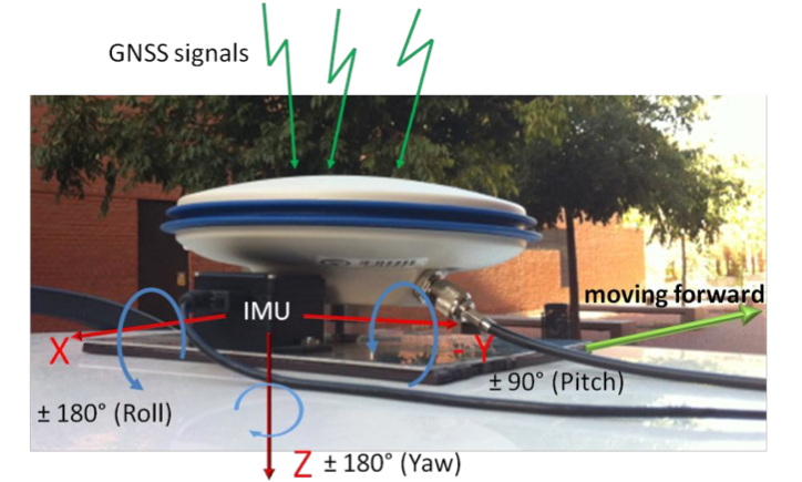
Integration of GNSS antenna of rover receiver and IMU in a platform over the roof of the vehicle.
The greatest problem presented by a commercial GPS in an urban setting is the loss of all satellite signals. “This occurs continually, but commercial receivers partially solve the problem by making use of the urban maps that attempt to position the vehicle in an approximate point,” Martín said. “These devices can indicate to the driver approximately where he is, but they cannot be used as a source of information in an Intelligent Transport System like those we have cited.”
The basic elements that make up this system are a GPS and a low-cost inertial measurement unit (IMU). The latter device integrates three accelerometers and three gyroscopes to measure changes in velocity and maneuvers performed by the vehicle. Then, everything is connected to a computer that has an application that merges the data and corrects the errors in the geographic coordinates. Enrique Martí of UC3M’s GIAA explains, “This software is based on an architecture that uses context information and a powerful algorithm (an unscented Kalman filter) that eliminates the instantaneous deviations caused by the degradation of the signals received by the GPS receiver or the total or partial loss of the satellites.”
The current prototype can be installed in any type of vehicle. It is already working on board the IVVI (Intelligent Vehicle based on Visual Information, pictured above), a car that has become a platform for research and experimentation for professors and students at the university.
The LSI and UC3M researchers working on this “intelligent car” can capture and interpret all of the information available on the road, and that drivers use. To do this, the team is using optical cameras, infrareds and lasers to detect whether drivers are crossing the lines on the road, or whether there are pedestrians in the vehicle’s path, as well as to adapt the speed to the traffic signals and analyze the driver’s level of sleepiness in real time.
Next Steps. The researchers will analyze the possibility of developing a system that makes use of the sensors that are built into smartphones, because intelligent telephones are equipped with more than ten sensors, such as an accelerometer, a gyroscope, a magnetometer, GPS and cameras, in addition to Wi-Fi, Bluetooth or GSM communications.
“We are now starting to work on the integration of this data fusion system into a mobile telephone,” said Enrique Martí, “so that it can integrate all of the measurements that come from its sensors in order to obtain the same result that we have now, but at an even much lower cost, since it is something that almost everyone can carry around in his pocket.”
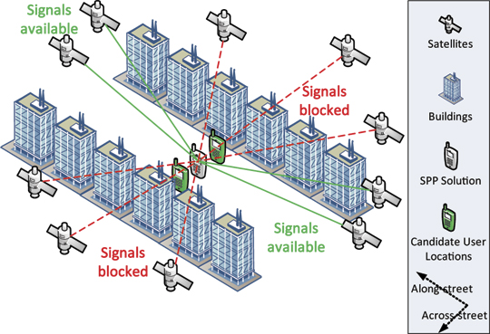
Shadow matching. The two GNSS mobile phones beside the middle one show additional possible user positions referenced by the along-street component of the standard point positioning (SPP) solution.
By Paul D. Groves, Lei Wang, and Marek K. Ziebart
GNSS positioning in dense urban areas is unreliable, with accuracy particularly poor in the cross-street direction. One solution is shadow matching, a new positioning technique that uses 3D building models to predict which satellites are visible from different locations and compares this with the measured satellite visibility to determine position. This article presents test results of a preliminary shadow-matching algorithm in a London urban canyon and discusses the practical implementation of the technique
Poor GNSS positioning accuracy is common in urban canyons where tall buildings block the direct line-of-sight (LOS) signals from many, sometimes most, of the satellites, effectively casting GNSS shadows over the adjacent terrain. Without direct signals from four or more satellites, an accurate position solution cannot be determined. Sometimes, a degraded position solution can be obtained by using signals that can only be received by reflection off a building, known as non-line-of-sight (NLOS) signals.
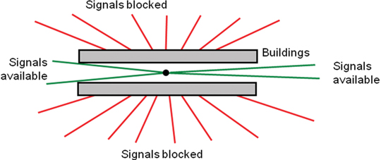
Using GLONASS in addition to GPS considerably enhances direct signal availability, and the ongoing deployment of Galileo and Compass will enhance it further. However, an urban canyon affects the geometry of the available GNSS signals as well as their number. Signals with lines of sight going across the street are much more likely to be blocked by buildings than signals with lines of sight going along the street (see Figure 1). As a result, the signal geometry, and hence the positioning accuracy, will be much better along the direction of the street than across the street. For example, for a building-height-to-street-width ratio of three and direct signals from four GNSS constellations, the cross-street position uncertainty can exceed 20 meters, while the along-street uncertainty is within 5 meters.
Figure 1. Signal geometry of GNSS satellites in an urban canyon (aerial perspective).
This level of accuracy is good enough for some applications but not others. Knowing which side of the street a pedestrian on is useful for visitor guidance and location-based advertising, while it is critical for guiding the blind and visually impaired and for augmented-reality applications. Similarly, lane-level positioning is important for advanced intelligent transportation systems that can direct individual vehicles in order to maximize traffic flow and prioritize emergency vehicles.
Improving GNSS positioning in urban canyons requires lateral thinking. If it’s not possible to calculate a sufficiently accurate position solution using the visible satellites, why not use the nonvisible satellites as well? This is exactly what shadow matching does. If you know where the buildings are and how big they are, you can deduce positional information from the knowledge that certain signals are blocked.
This requires a 3D model of a city’s buildings. These are becoming more accurate and widely available and have already been used to predict GNSS signal availability and multipath interference.
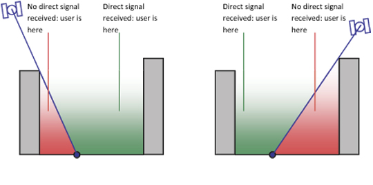
The principle of shadow matching is simple. Due to obstruction by buildings in urban canyons, signals from many GNSS satellites will be receivable in some parts of a street, but not others. Where each direct signal is receivable can be predicted using a 3D city model. Consequently, by determining whether a direct signal is being received from a given satellite, the user can localize their position to within one of two areas of the street. Figure 2 illustrates this. By considering other satellites, the position solution may be refined further, producing a much more accurate cross-street position solution than available from conventional GNSS positioning in this environment. Thus the observed signal shadowing is matched with the predicted shadowing to determine position.
Figure 2. The shadow-matching concept: using direct signal reception to localize position.
This concept of shadow matching, has been proven by mathematical modeling. Satellite visibility predictions using a 3D city model of London have been validated with real-world observation, demonstrating the practical potential of shadow matching. Here, shadow matching is brought from proof of concept one step further to practical demonstration. A preliminary but complete implementation of shadow matching has been developed and tested in London using real-world GPS and GLONASS measurements. The algorithm is described first, followed by the test results. We then discuss dealing with different types of signal propagation that occur in urban areas. and how to implement shadow matching in real time on a platform such as a smartphone.
Shadow-Matching Algorithm
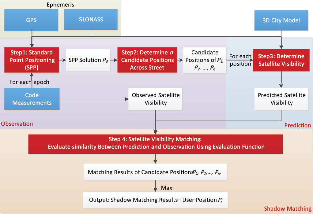
A basic shadow matching algorithm may be broken down into four steps:
Perform standard point positioning (SPP) using GNSS pseudo-ranges to obtain an approximate user position.
Define the search area for the shadow-matching position solution, generating a set of possible user positions close to the approximate position solution.
Predict satellite visibility at each candidate position using the 3D city model.
Evaluate the similarity between predicted and observed satellite visibility at each position. The candidate position with the best match is deemed to be the shadow-matching solution. This process can be conducted epoch by epoch, so the GNSS user can be either static or dynamic.
Conventional Positioning. In the first step, SPP using GNSS pseudo-ranges is conducted to acquire an initial user position. In an urban environment, the accuracy will often be poor, partly due to contamination by NLOS signals. Consistency checking may be used to identify the NLOS signals and, where possible, remove them from the position solution.
Candidate Position Determination. As discussed earlier, signal geometry and hence positioning accuracy will be much better along the direction of the street than across the street. Therefore, in this preliminary shadow-matching algorithm, the along-street component of SPP solution is used as a reference to generate a set of possible user positions that vary in across-street direction only (shown by the two mobile phones beside the SPP solution on the opening page of this article).
A more advanced shadow-matching algorithm would also consider candidate positions in the along-street direction and would vary the size of its search area based on an assessment of the quality of the SPP solution. The smaller the search area, the more efficient the shadow-matching algorithm will be. However, the search area must be large enough to contain the true position. Further research is needed to determine the optimum search area.
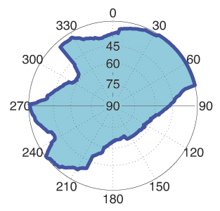
Satellite Visibility Prediction. At each candidate position, the two-step building boundary method predicts satellite visibility from the 3D city model. First, a building boundary from a GNSS user’s perspective is determined for each azimuth (from 0 to 360°) as a series of elevation angles. The results from this step show where the building boundaries are located within an azimuth-elevation sky plot. Figure 3 shows an example of a building boundary computed from a possible user location. Once the building boundary has been computed, it may be stored and reused.
Figure 3. Example of a building boundary as azimuth-elevation pairs in a sky plot. (The centre of the plot correspond to a 90º elevation or normal incidence).
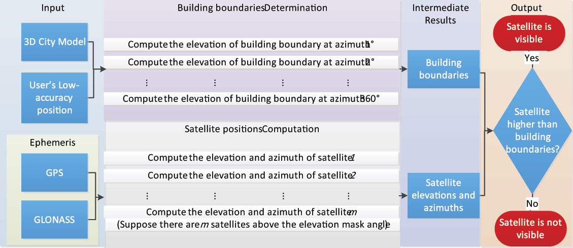
Next, each satellite elevation is compared with the building boundary elevation at the same azimuth. The satellite is predicted to be visible if it is above the building boundary. If the satellite is just within the building boundary, a potentially diffracted signal can be predicted. However, this feature was not included in the preliminary shadow-matching algorithm described here. A software toolkit for determining satellite visibility was developed in C++.
Figure 4 shows the relationships between its processes.
Figure 4. The process of satellite visibility prediction. (Click to enlarge.)
The building boundary approach is efficient where a great number of satellite visibility tests are performed at the same location. For real-time visibility determination, building boundaries may be pre-computed over a grid of possible user locations and stored. However, there is an alternative. Instead of computing building boundaries, each satellite LOS can be directly compared with the city model to determine if it is blocked by buildings. This single LOS method is more efficient overall where only a few satellite visibility tests are performed at a given location. However, for real-time, it imposes a much higher processing load than using pre-computed building boundaries.
In practice, either method may be employed, depending on the situation. For real-time shadow matching, the trade-off is between a higher processing load for the single LOS method and greater data storage for the building boundary method. For non-real-time visibility determination, the trade-off depends on the number of tests required at each location.
Matching Prediction and Observation. The final step, evaluating the similarity between predicted and observed satellite visibility at each position and identifying the best match as the shadow matching solution, comprises three functions: satellite matching, position scoring, and position comparison.
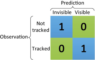
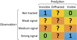
Satellite matching determines for each satellite the degree of similarity between the predicted satellite visibility and the real observation. Figure 5 shows the simple satellite matching function deployed for this study. For each satellite above a pre-set elevation mask angle, if the prediction agrees with the observation, the score is one; otherwise, the score is zero.
Figure 5. Scoring matrix giving the score for each satellite in shadow matching.
Future research will be conducted to extend the matching function so that different scores are produced for signals predicted to be in the diffraction region and signals observed with low and medium signal-to-noise levels.
Position scoring evaluates the overall degree of match between predicted and observed satellite visibility for each possible user position, summing up the satellite matching scores for each candidate position to give a position score.
Finally, position comparison selects the candidate position with the highest overall score and outputs this as the position solution. However, sometimes there is more than one candidate. Further research is needed to find the optimum way of determining a positioning solution with associated error bounds from a grid of shadow-matching scores.
Figure 6 summarizes the shadow-matching process.
Figure 6. The shadow matching process. Blue denotes input data, red denotes main process steps, and white denotes intermediate or final results. (Click to enlarge.)
Experimental Verification
We used a 3D city model of the Aldgate area of central London to test shadow matching. The model has a high level of detail and decimeter-level accuracy.
The software toolkit developed for this study stores and processes 3D city model data using Virtual Reality Modeling Language (VRML), an international standard format. Model data in other formats can be transformed to VRML. Buildings in VRML format are represented by structures, which in turn comprise polygons (normally triangle meshes).
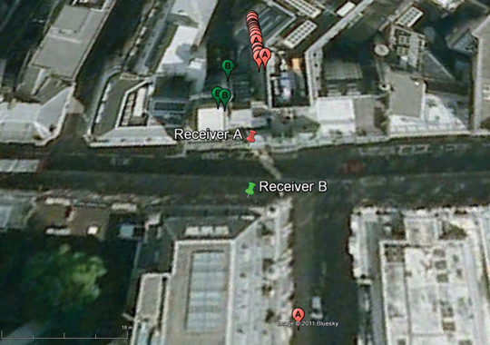
Methodology. Experimental data were collected in a highly built-up area in central London, using two multi-constellation survey-grade GNSS receivers, logging 1 Hz data simultaneously (note that shadow matching does not require two receivers). As shown in Figure 7, they were set up on the north and south sidewalks of Fenchurch Street.
Figure 7. True position of receivers against conventional standard point positioning (SPP) solution. Pins show the true positions and bubbles the SPP solutions; the numbers and colors indicate the receiver.
For the first step of shadow matching, software was used to conduct SPP processing using GPS and GLONASS signals. Only L1 pseudo-ranges were used to acquire an initial user position. It can be seen in Figure 7 that the conventional SPP solutions have significant offsets from the true positions (16–31meters for receiver A and 18–24 meters for receiver B). As receiver B suffers more signal blockage from buildings, it has fewer epochs with four or more satellites in view, so fewer successful SPP GNSS solutions were obtained. Although they have significant offsets in the across-street direction, they are consistent and agree much more with the receivers’ true positions in the along-street direction. This result verifies the assumption made in the shadow-matching algorithm that the accuracy of the along-street SPP positioning solution is much better than in the across-street direction.
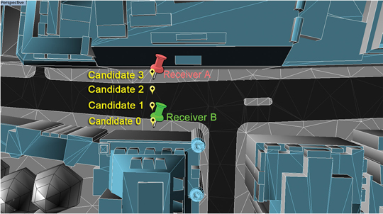
Four candidate user positions were selected using the common along-street position of the conventional SPP solution. They are distributed across the sidewalks and vehicle lanes, on both sides of the street. Figure 8 illustrates this. Note that candidate 3 is the true position of receiver A and candidate 0 is the true position of receiver B.
Figure 8. Candidate user positions (in yellow) and true receiver positions (in red and green) in the shadow matching experimental verification.
Satellite visibility was predicted individually for each of the four positions. Then each was compared with the real data observed from the two GNSS receivers. Figure 8 shows part of the architectural city model of London used to predict the satellite visibility.
Results. The experimental results are shown in three stages: the satellite visibility comparison between prediction and observation, the candidate position scoring function, and the success rate for each candidate location. The primary success criterion is whether the algorithm is able to determine the correct side of the street. A secondary aim is to test whether the algorithm can distinguish between the sidewalk and vehicle lane on the same side of the street.
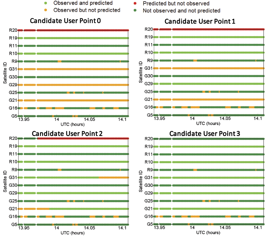
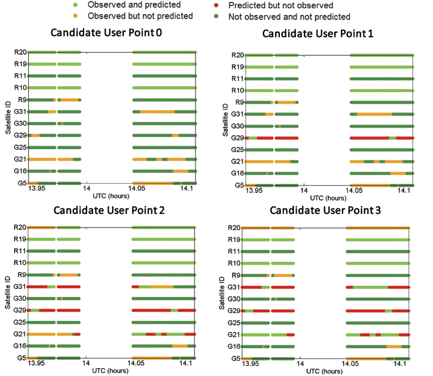
To show the degree of agreement or disagreement between the predicted and observed satellite visibilities, time series for each of the four candidate positions are compared with each of the two receivers’ experimental data. The results are shown in eight graphs. Figure 9 compares data from receiver A for each of four possible user locations. Figure 10 shows the same comparison for receiver B. The time window was from 13:56:30 to 14:06:30 (UTC). G denotes GPS satellites and R refers to GLONASS satellites.
In Figure 9, the green and blue dots indicate an agreement between prediction and observation for the candidate user position, while the orange and red colors represent their disagreement. Thus, a larger number of cases of green and blue indicate a better match between the candidate user location and the observations. Therefore, such a candidate is more likely to be close to the receiver’s true position.
Figures 9 and 10 clearly show that the closer the candidate position is to the true position, the greater the agreement between predictions and observations.
Figure 9. Comparison of satellite visibility between receiver A and candidate user locations (candidate user point 3 is the true position). (Click to enlarge.)
Figure 10. Comparison of satellite visibility between receiver B and candidate user locations (candidate user point 0 is the true position). (Click to enlarge.)
Even at the correct candidate location, there is not complete agreement between the observations and predictions. A number of signals were observed but not predicted. These had signal-to-noise levels 8 dB or more lower than the predicted signals and are most likely due to reflection and/or diffraction.
However, shadow matching does not require complete agreement in order to work. In this test, no signals were predicted but not observed at the correct location.
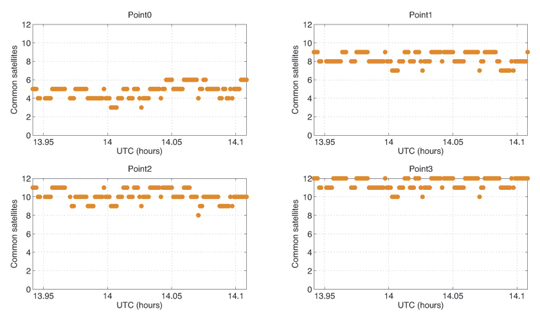
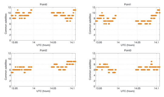
To complete shadow matching, we evaluate each candidate position by summing up the number of satellites common to both the predictions and real observations. Figure 11 and Figure 12 show the results of the summation for receivers A and B, respectively.
Figure 11. Evaluation of similarity — number of common satellites in view between each candidate user point and receiver A.
Figure 12. Evaluation of similarity — number of common satellites in view between each candidate user point and receiver B.
It is clear from Figure 11 that among four possible user positions, point 3 is the one with the highest agreement score with the observations from receiver A. As shown in the right-bottom graph, for about half the epochs, visibility predictions for all 12 satellites above the masking angle match the real observations.
As shown in Figure 12, for receiver B, the time series of the agreement score is generally better at the true location (Point 0) than at other points. However, the level of agreement between predictions and observations is not as good as at receiver A‘s location.
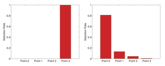
To judge the performance of shadow matching, the selection rate of each of the four candidate user positions for each of the two receivers was computed by dividing the number of times that position was selected by shadow matching by the number of epochs. Where the same score was attained for two or more positions, each position was considered partially selected. For example, if two positions have the same score, then each of them is considered half-selected.
The selection rate results are shown in Figure 13. For receiver A, the shadow matching algorithm correctly indicated the true position among the four candidates 100 percent of the time. This means the algorithm successfully distinguished between the two sides of the street, and further distinguished between a user on the sidewalk and a user in the vehicle lane. For receiver B, the algorithm identified the correct side of the street (Points 0 and 1) 94.65 percent of the time, and the correct location among the four candidates in 81.29 percent of the epochs evaluated.
Taking the average of the two test sites, the correct side of the street was identified 97.3 percent of the time and the correct position from the four candidates 90.6 percent of the time.
Figure 13. Candidate position selection rate for receiver A (left) and receiver B (right).
Practical Implementation
The basic shadow-matching algorithm operates under the assumption that GNSS signals are either directly visible or blocked by a building. However, in reality, signals can also be received via indirect paths due to reflection or diffraction. This was observed at both locations during the tests. As shadow matching seeks the position with the best match, rather than looking for a perfect match, it can tolerate a certain number of these signals and still identify the correct position.
These tests were performed using survey-grade user equipment with a relatively high tracking threshold, so the weakest signals are not observed. Furthermore, the antenna has strong polarization discrimination so exhibits a low gain for reflected signals. However, for shadow matching to be practical, it should also work on a smartphone, which typically combines a high-sensitivity receiver with a linearly polarized antenna, which does not distinguish between direct and reflected signals. Consequently, a smartphone receiver is likely to observe more reflected and diffracted signals.
NLOS reflected and diffracted signals are weaker than directly-received signals, so the shadow-matching algorithm could be modified such that only signals received above a certain signal-to-noise threshold are classified as observed. However, this would introduce a new problem: signals received via a direct LOS path but attenuated by a person’s body would be classified as not observed, even though they would be predicted to be visible at the correct location. The same problem would occur where the LOS coincides with a direction in which the antenna is weak. Consequently, to get the best performance from shadow matching, several different categories of observed signal should be considered in the scoring matrix.
Diffraction occurs when the LOS is just inside the building boundary. Therefore, the 3D city model can be used to predict when a diffracted signal may be received. However, it cannot easily be used to predict the signal-to-noise level of that signal because diffraction patterns are complex. Therefore, shadow matching can potentially be improved by adding a third prediction category for diffraction. Figure 14 shows a posssible optimized scoring matrix with values between 0 and 1 for the new categories to be determined empirically, possibly as functions of the measured signal-to-noise. Different scoring matrices may be suited to pedestrian and vehicle applications and to different user equipment designs.
Directly-received signals are also affected by multipath interference. However, this will not normally impact shadow matching as it does not affect whether a signal is received or not.
Shadow matching has been demonstrated using both GPS and GLONASS measurements. The more signals available for shadow matching, the better the expected accuracy and reliability. Thus, the addition of Galileo, Compass, and regional systems, including SBAS, should improve performance. However, further research is needed to determine whether shadow matching using GPS alone is viable. Combining data from multiple epochs should also improve shadow matching performance, particularly where the user is moving.
A practical shadow-matching algorithm must be implementable in real time on a mobile device. Three models maybe considered.
A network-based solution, whereby GNSS measurements are transmitted to a server, which stores the building boundary data, computes a solution and then sends it to the user.
A handset-based solution, where the shadow-matching algorithm is run on the handset, which also stores the building boundary data.
A hybrid model, whereby the shadow-matching algorithm runs on the handset, but the building boundary data is streamed from a server as and when required.
Using stored or streamed building boundaries, fewer than fifty comparison and addition operations are required to calculate an overall shadow-matching score for one candidate position with two GNSS constellations. Therefore, shadow matching may be performed in real time on a mobile device with several hundred candidate positions, where necessary.
Without any data compression, about 300 bytes are required to store a building boundary with a 1° resolution. If a 2×2 meter grid spacing is used for the candidate positions, a 1-kilometer long, 20-meter wide street will contain 5000 grid points, requiring 1.5 MB of data storage. By exploiting the similarities both between neighboring azimuths in the same building boundary and between building boundaries at neighboring grid points, substantial data compression should be achievable; possibly up to a factor of ten.
Therefore, a standard 4 GB flash drive could store building boundary data for 2,500–25,000 kilometers of road network. For comparison, the Greater London metropolitan area contains about 15,000 km of road. However, as shadow matching is only useful in streets where conventional GNSS positioning is poor, the database need only contain building boundary data for these streets, maybe 10 percent of the total. Therefore, it should be practical to preload a mobile device with shadow-matching data for several cities, which could be kept up-to-date via the internet.
An alternative model is to download the building boundary data from a network server as required. A conventional GNSS position solution or Wi-Fi fix should be able to localize position to within 1,000 grid points, requiring 30–300 kB of building boundary data to be downloaded in order to perform shadow matching. This takes less than two seconds using a 3G mobile phone connection with an average data rate.
In practice, shadow matching, would be implemented as part of a wider intelligent urban positioning system. This shadow-matching algorithm assumes that the user is outdoors. Indoor operation, if viable, would require a different approach. It is necessary to determine the error bounds of the conventional GNSS position solution, not only to determine the search area for shadow matching, but decide whether shadow matching should be performed at all. For example, in a completely open-sky environment, shadow matching will fail, but a good position solution will be obtainable conventionally.
There are other ways in which 3D city models could be used to improve GNSS positioning. For example, they could aid identification of NLOS and multipath-contaminated signals and, in principle, even correction of NLOS ranging measurements. Intelligent urban positioning can also incorporate additional sensors, such as odometers on cars and cell phone signals, WiFi and inertial sensors for pedestrian users.
Next Steps
Three potential future lines of research stem from this work: improving the initialization from conventional GNSS positioning, improving of satellite visibility predictions with ambiguous observations, and optimizing the position determination from the shadow-matching scores. In addition, performance will be evaluated over a wider range of environments.
Acknowledgments
The authors gratefully acknowledge Kimon Voutsis for his support with the experiments. This work has been jointly funded by the University College London Engineering Faculty Scholarship Scheme and the Chinese Scholarship Council. This article is based on a paper presented at the 2011 European Navigation Conference in London, organized by the Royal Institute of Navigation.
Manufacturers
The tests used two Leica Viva GS15 GNSS receivers. Leica Geo-office software performed SPP processing of GPS and GLONASS signals. ZMapping Ltd. supplied the London 3D model.
Paul Groves is a member of the academic faculty at University College London (UCL), where he leads the Space Geodesy and Navigation Laboratory’s program of research on robust navigation and positioning. He is also author of the book Principles of GNSS, Inertial, and Multisensor Integrated Navigation Systems.
Lei Wang is a Ph.D. student at UCL. He received a Bachelor’s degree in geodesy and geomatics from Wuhan University in 2010. His current research interests are GNSS-based positioning techniques for urban canyons.
Marek Ziebart is professor of space geodesy, director of the Space Geodesy and Navigation Laboratory, and vice dean for research of UCL Engineering.