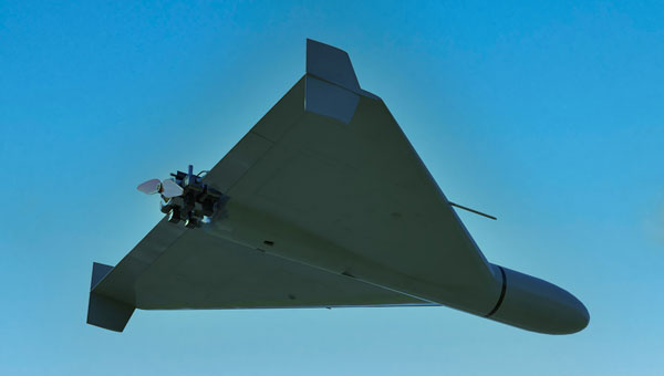
General Atomics Aeronautical Systems Inc. (GA-ASI) is in the news again, as it got its prototype version of the U.S. Air Force (USAF) Collaborative Combat Aircraft (CCA) into the air for the first time, with an anticipated lengthy flight test campaign to follow. This latest CCA iteration, refered to as the YFQ-42A CCA, was derived from an earlier jet-powered XQ-67A Off-Board Sensing Station, a platform that enabled the company to not only develop and build but also fly this latest aircraft in just one year.
GA-ASI CAA makes first flight Aug. 27, 2025. (Credit: GA-ASI)
The UAV features significant autonomous capabilities developed over nearly five years of training using the MQ-20 Avenger unmanned jet aircraft. The strategy of beginning with a company-developed baseline aircraft (Avenger), securing USAF support for an initial derivative and then for the YFQ-42A CCA, appears to be accelerating development of the Loyal Wingman concept toward USAF operational manned-unmanned airborne teaming.
Previously, in July, GA-ASI began preparations to enable friendly European countries to rapidly participate in the future CCA-capabilites by teaming with its German affiliate General Atomics Aerotec Systems GmbH (GA-ATS). The agreement appears to enable high-volume local manufacture of a European CCA, and press releases have implied that potential content is expected to be provided by other high-tech local suppliers.
Following earlier reports that Reliable Robotics (RR) has been busy automating all phases of aircraft operations, including a Cessna Caravan cargo aircraft, USAF has awarded RR a $17.4 million contract to install a Reliable Autonomy System (RAS) in another Cessna. The resulting automated Cessna 208A Caravan is to be used in an estimated two-year program toward obtaining FAA certification that should enable flight within the U.S. National Airspace System (NAS). The system has been demonstrated — with a remote pilot in the loop — to be able to take an aircraft from startup on the ramp, through taxi, takeoff, en route flight, landing and taxi return to the ramp for unloading.
RR autonomous Cessna 208B takes off from Mojave Air and Space Port, California, on Aug. 8, 2024. (Credit: RR)
Cessna Caravans have been heavily used for cargo transport across the U.S. (and around the world) with a range of 1000 miles, carrying up to 1000 lb of cargo. The RR certification program is intended to allow these types of automated unmanned commercial and military operations on a regular basis throughout FAA controlled US airspace, alongside manned aircraft. Flying military unmanned aircraft in the NAS currently requires extremely highly-coordinated, continuous activity. The hope is that eventually it could become an easier more regular form of autonomous cargo/people air transport.
The cost of the continuing war in Ukraine may be affecting the Russian economy — a major drone manufacturer apparently is facing bankruptcy despite Russia currently using thousands of drones in attacks on Ukraine. The situation is difficult to understand, but this is an expensive war.
However it appears that, AO Kronshtadt, one of the major drone suppliers in Russia is also beset by civil lawsuits from several organizations to which it owes lots of rubles. Its Orion and an updated version Inokhodets drone are apparently somewhat similar to the US MQ-9 Reaper UAV.
AO Kronstadt employees assemble the Russian Orion UAV. (Credit: open source)
Russia has apparently converted the Orion/Inkhodets medium-altitude surveillance drone into a strike version, but with limited success. Nevertheless, Kronshtadt apparently has made some progress, selling an export version in Asia.
Meanwhile, Russia still is apparently producing up to 6,000 Shahed one-way drones per month by another manufacturer in the Alabuga Special Economic Zone at a unit cost of around $70,000. This is significantly lower than drones that were originally purchased from Iran at $370,000 each.
The U.S. Federal Government through its transport agencies apparently has the exclusive right to control drones, including bringing malicious UAVs down from the sky. Most people understand that the Federal Aviation Administration (FAA) regulates who flies what and where, but who is in charge of reducing and removing drone threats? It may have been difficult to understand during recent unauthorized overflights of military installations on the East Coast why someone didn’t shoot down the offending drones.
Now, a group of police agencies has approached members of Congress to ask for the right to “detect, track, identify and mitigate” the unlawful, negligent or malicious use of drones that threaten public safety. Citing a number of incidents — including drone incursions at airports and other incidents where unmanned aircraft have interfered with firefighting and disaster response, instances where law enforcement activities have been overflown and disrupted, and the practice of using drones to drop drugs, guns and mobile phones into prisons — the law enforcement group sees a need for permission to engage. With several major events scheduled across the U.S., it likely is time to support law enforcement with the appropriate powers needed to protect the public.
It is true that several bills are already pending before Congress to enable state, local, tribal and territorial law enforcement agencies to find, identify and possibly mitigate inappropriate drone activity, but the group is urging action now. And they clearly demonstrate the need to be able to stop drone activity when necessary — the federal government cannot cover the whole country all the time, so it makes more sense to adequately train law enforcement and to distribute authorized local mitigation activity whenever it is found to be necessary.
So a mixed bag this month — progress for the U.S. Collaborative Combat Aircraft initiative, more steps toward automation for air cargo transport, problems for one Russian drone supplier while others increase volume and the United States seeks options for better defense against them, and U.S. law enforcement seeks the capability to help mitigate drone incursions where they are not wanted — plenty of different angles to consider around unmanned aerial vehicles.
SandboxAQ has been awarded a Direct-to-Phase-II Small Business Innovation Research contract by the United States Air Force. SandboxAQ will test and evaluate its quantum sensor prototype to help protect military navigation resilience.
Under the contract, SandboxAQ will advance research and development for its quantum navigation system, which is being designed to complement GPS. It will be used for accurate navigation in contested or denied environments where the loss of precision GPS may negatively impact operations.
SandboxAQ’s AQ-powered quantum sensor prototype will be optimized in close coordination with USAF through identified innovation areas, including live demonstrations aboard USAF aircraft. The sensor prototype also has potential for use in the commercial sector for aviation, unmanned vehicles and more.
An accuracy test of the Locata Network — a non-GPS-based positioning system installed at the U.S. Air Force White Sands Missile Range in New Mexico — focused on timing down to the nanosecond, with impressive results.
In 2018, the 746th Test Squadron (746 TS) tested its Non-GPS-Based Positioning System (NGBPS) at White Sands Missile Range as an alternative to GNSS for precise time transfer and synchronization. This was the first independently measured and characterized testing program for the NGBPS, which leverages Locata’s radio-based position, navigation and timing (PNT) technology to achieve high accuracy independent of GPS.
Using specific parameters and equipment configurations, independent experts proved Locata’s absolute and relative time synchronization and frequency stability performance. Under testing, the NGBPS provided exceptional time transfer and frequency stability across large areas.
With these successful results in hand, the U.S. Department of Defense will be able to leverage this capability for programs requiring high-precision time and frequency distribution, without relying on GPS alone. Plus, the system is flexible — Locata’s area of transmission can be increased to cover substantially larger areas than at White Sands for safety-of-life, military or government-mandated systems.
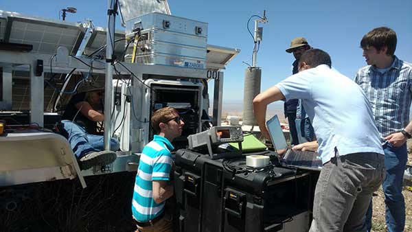
With USNO personnel, members of the 746 TS reconfigure the Master LocataLite site for the test. (Photo: 746 TS/USAF)
Background
Over the past two decades, the free availability of GPS time has enabled a plethora of time-dependent applications. Time and frequency synchronization between remote locations is crucial for digital communication systems, electrical power grids and financial networks, to name a few. Military operations also require accurate and reliable time information. Typically, these applications require accurate time synchronization ranging from 10 microseconds (μs) down to 100 nanoseconds (ns). Yet, while our critical reliance on GPS for time transfer continues to escalate, GPS remains susceptible to interference, disruption or denial.
A technician with the 746 TS re-aims a LocataLite antenna for an alternative TimeLoc configuration. (Photo: 746 TS/USAF)
Locata. Locata Corp., a privately owned Australian company with a U.S. subsidiary, invented a radio-location technology that provides precise PNT for environments where GPS coverage is unavailable. Locata ground-based PNT technology delivers positioning that, in many scenarios, far exceeds the performance and reliability of GPS. LocataNets, the company’s terrestrial networks, function as local ground-based replicas of traditional GPS position and timing services. They can be designed to reliably deliver a powerful, controllable, tailored signal as user applications require.
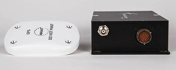
A LocataNet consists of synchronized LocataLite transceivers, all-in-one units that transmit and receive out of the same 10 x 5 x 1-inch box. Cables are connected to antennas for signal reception and transmission. Locata Rovers are mobile receivers within the network that use these synchronized LocataLite signals to calculate an accurate PNT solution.
The 746 TS employs the basic LocataNet laydown — multiple Slave LocataLites receive signals from a single Master LocataLite transceiver. The patented process by which slaves are synchronized to the master (or other slaves) is known as TimeLoc.
Until these new tests were run, the squadron’s attention had primarily been focused on the high-accuracy use of Locata’s position and navigation solution as an alternative to GPS when it is jammed, deceived or unreliable. But because all LocataLites are precisely synchronized via TimeLoc, network synchronization is a natural extension of Locata technology’s core capabilities.
In October 2015, GPS World reported that the United States Naval Observatory (USNO) showed LocataLites are a viable option for a stable 1 pulse per second (1 pps) distribution setup within an urban environment, where it can support applications such as cell-tower synchronization in GPS-challenged environments. The USNO tests demonstrated synchronization of less than 200 picoseconds — significantly better than any other known wireless network synchronization methodology, including GPS. If clear line-of-sight is available between a master and Slave LocataLite, precision is 50 picoseconds with frequency stability to 1×10-15 —better than a Stratum One atomic clock.
Because of the USNO’s timing expertise and familiarity with Locata TimeLoc testing, the 746 TS tasked the USNO to conduct independent synchronization experiments at White Sands, with the following objectives:
Evaluate the Locata master, slaves and non-Locata timing receiver at the master site in reference to USNO master atomic clock time.
Determine the Locata network’s internal, independent synchronization stability and accuracy.
Determine the Locata Rover’s 1 pulse per second (PPS) time stability and accuracy, for use in time transfer applications.
The primary purpose of the tests was to show that nanosecond-level time transfer is possible over significantly wide areas by using Locata, and that TimeLoc technology offers a relatively easy means of supporting exceptionally high-precision time and frequency distribution over large broadcast areas.
Slave LocataLite site layout. (Photo: 746 TS/USAF)
Synchronization Method
Since Locata technology was originally developed as an RF-based high-precision non-GPS-based positioning and navigation system, the time synchronization accuracy requirements for a LocataLite transceiver are very high. If centimeter positioning precision is desired for a Locata receiver, every small fraction of a second is significant; for instance, a 1-ns error in time equates to an error of approximately 30 centimeters (because of the speed of light).
TimeLoc is a patented high-accuracy wireless synchronization method developed by Locata Corp. It allows LocataLites to achieve high levels of synchronization without atomic clocks, external control cables, differential corrections or a master reference receiver.
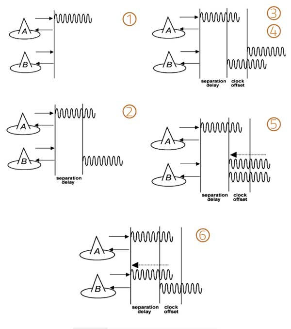
The TimeLoc procedure is described in the following steps for synchronizing two LocataLites (see Figure 1).
LocataLite A transmits a unique signal (code and carrier).
The receiver section of LocataLite B acquires, tracks and measures the signal generated by LocataLite A.
LocataLite B generates its own unique signal (code and carrier) which is transmitted, but, importantly, it is also received by the receiver section of LocataLite B.
LocataLite B calculates the difference between the signal received from LocataLite A and its own locally generated and received unique signal. Ignoring propagation errors, the differences between the two signals are due to the clock difference between the two devices and the geometric separation between them.
LocataLite B adjusts its local oscillator to bring the differences between its own signal and LocataLite A to zero. The signal differences are continually monitored and adjusted so that they remain zero. In other words, the local oscillator of B follows precisely that of A.
The final stage is to correct for the geometrical offset (range) between LocataLite A and B, using the known coordinates of the LocataLites. When this step is accomplished, TimeLoc has been achieved.
Figure 1. The TimeLoc process. (Image: Author)
The only requirement for establishing a LocataNet using TimeLoc is that LocataLites must receive signals from one other LocataLite. However, received signals do not have to come from the same central or Master LocataLite, because this may not be possible in difficult environments or when propagating the LocataNet over large areas. Instead, a LocataNet can “cascade” TimeLoc through intermediate LocataLites. For example, if a third LocataLite C can only receive the signals from B and not Master LocataLite A, it can use B’s signals for time synchronization instead of A’s, provided that B has already TimeLoc’d to the network. Therefore, by using “cascaded TimeLoc,” there is theoretically no limit to the number of LocataLites that can be synchronized.
Test item description
The NGBPS at White Sands consists of an operational LocataNet, where each node (a site instrumented with a LocataLite) is synchronized via Locata’s patented TimeLoc technique. The LocataNet, combined with a mobile Rover, is a subsystem of the 746 TS Ultra-High-Accuracy Reference System (UHARS), which provides PNT information in GPS-denied environments. The NGBPS operates in the 2.4-GHz industrial, scientific and medical band, which is far enough away from GPS frequencies to be unaffected by GPS jamming. Although it is currently used as a source of position truth during GPS jamming, the 746 TS understands that the NGBPS is potentially a source of high-accuracy timing data as well.
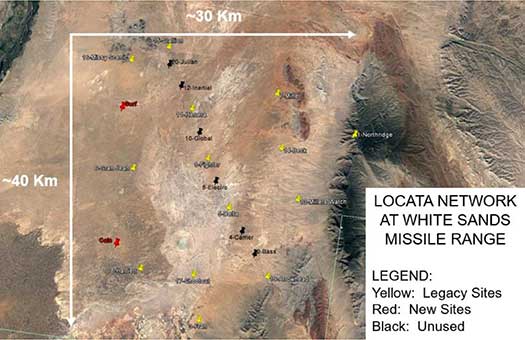
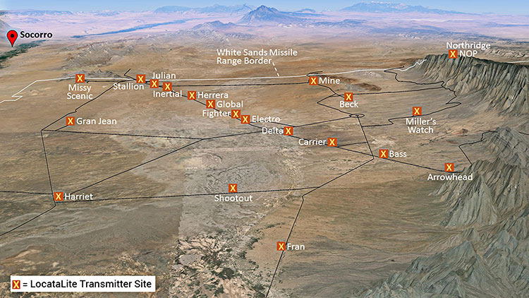
The UHARS is in the northern portion of White Sands Missile Range. It typically consists of 16 LocataLite sites. The master site is at North Oscura Peak, or NOP (labeled Northridge in Figure 2); all other sites are time synchronized to that master site.
Figure 2. Locata network at White Sands Missile Range. (Image: Author)
Each LocataLite site consists of:
one LocaLite
two monuments—pillars for antenna placement (Note: The two new sites lack the permanent monuments for antenna placement)
two transmit antennas
one receive antenna
one meteorological station—for meteorological data
one communication antenna
one trailer for power and transport
The communications antenna at each site is attached to a UHF modem that is used for 746 TS remote control of the LocataNet. This allows remote data logging, reconfiguration or monitoring of the network without having to drive to each site. However, it should be noted that no communications system whatsoever is required for the Locata NGBPS TimeLoc capability to run.
To support the timing tests, the LocataNet was reconfigured several times to meet requirements of specific test objectives. These configurations are described below.
Static ground tests
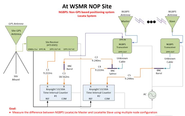
Static ground tests involved multiple configurations. The first (Figure 3) consisted of two LocataLites (master and terminal slave) collocated at NOP close enough that their respective PPS outputs could be compared in a single time interval counter. A terminal Slave LocataLite was installed at NOP specifically for this test.
Figure 3. LocataLite Configuration 1: North Oscura Peak (NOP) site test instrumentation. (Image: Author)
This setup also facilitated simple network reconfiguration to change the number of LocataLite sites being tested. By programming LocataLites to TimeLoc to specific sites at White Sands and redirecting their respective antennas accordingly, the TimeLoc chain under test could be expanded to have multiple sites between the LocataLite master and the collocated terminal slave without changing measuring equipment instrumentation at NOP. This means that the time transfer could hop, or cascade, between one or more sites and be measured with the same test instrumentation.
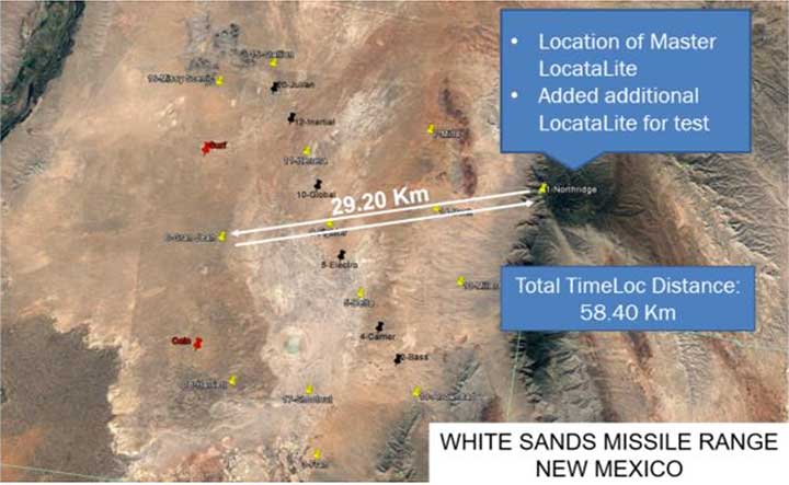
Configuration 2 consisted of three LocataLites: The master at NOP, a slave at Gran-Jean and the terminal slave at NOP. Again, the master and terminal slave were collocated close enough to each other that their respective PPS outputs could be compared in a single time interval counter, but this time the network was configured to cascade the TimeLoc signal through the slave at Gran-Jean, 29.20 km away. Since the TimeLoc signal now had to cascade through two sites and travel from the master at NOP to Gran-Jean and back to the terminal slave at NOP, the effective TimeLoc travel distance was 58.40 km (Figure 4).
Figure 4. LocataLite Configuration 2: Total TimeLoc distance is 58.40 km. (Image: Author)
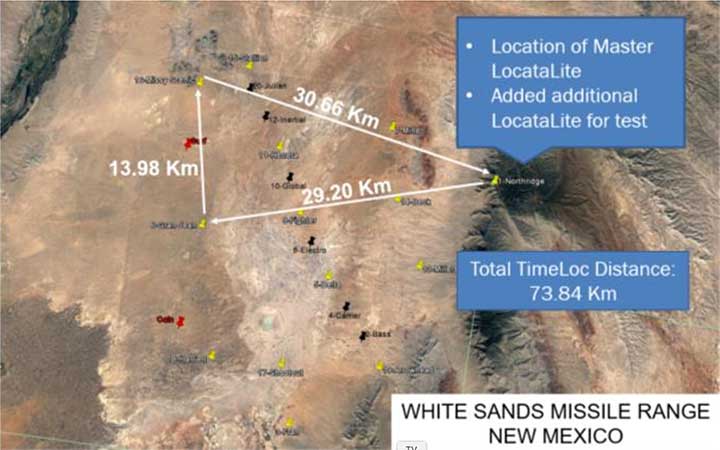
Configuration 3 consisted of four LocataLites: The master at NOP, a slave at Gran-Jean, a slave at Missy-Scenic and the terminal slave at NOP. This configuration forced the TimeLoc signal to cascade through three sites and travel a total distance of 73.84 km (Figure 5).
Figure 5. LocataLite Configuration 3: Total TimeLoc distance is 73.84 km. (Image: Author)
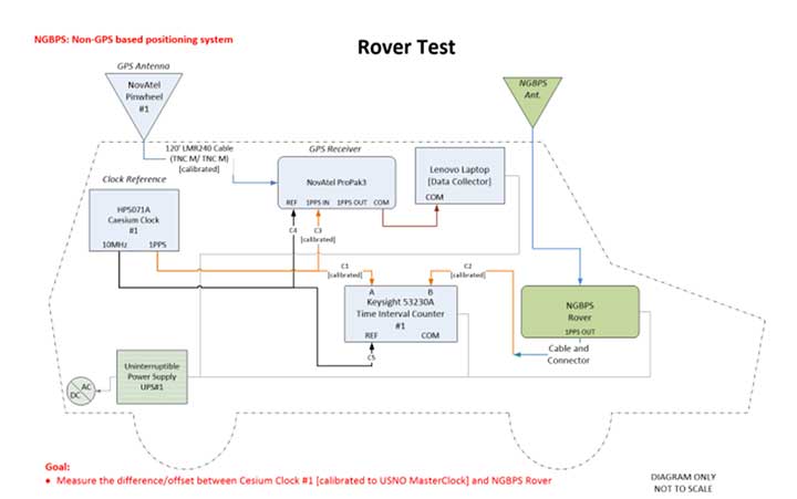
Ground vehicle test
For Configuration 4, a Locata Rover was instrumented on the squadron’s Small Test Vehicle (STV), which drove all accessible roads within the LocataNet’s coverage (Figure 6). During this mobile test, the LocataNet was configured with 10 active LocataLites. The Locata Rover in the vehicle used Locata signals from available nodes to calculate Locata network time, which was synchronized to the GPS timing receiver at NOP. The data collected determined how well network time is synchronized while in a moving vehicle.
Figure 6. Rover test installation on Small Test Vehicle. (Image: Author)
Test results
To collect the required data, USNO first had to characterize the performance of the master site’s GPS timing receiver at NOP, and then synchronize it to two separate USNO atomic clocks that could be used as remote timing references for the tests. The GPS timing receiver is equipped with a rubidium oscillator, which produces a GPS-disciplined 1 pps output signal. Its internal rubidium clock is a stable source of time with an advertised UTC (USNO) offset of a best case 15-ns root mean square (RMS) and a worst case 100-ns RMS.
The cesium clocks output 5- or 10-MHz sinusoids and a 1 pps signal. The cesium clocks output 5- or 10-MHz sinusoids and a 1 pps signal and were characterized relative to the USNO correction receiver, which USNO personnel had characterized relative to UTC. Correction data available from a time interval counter could then be applied to tie the timing receiver back to USNO time. The measurements at NOP recorded the difference between the timing receiver and the cesium clocks. Using the relationship between the cesium clocks and UTC (USNO), one could characterize the timing receiver’s time relative to USNO time.
The USNO calibrated measurements at the nanosecond level using two methodologies. The most common approach was simply to compare two 1 pps signals, a method known as “tick-tick.” Another important methodology is referred to as a “tick-phase,” which is a measurement of a sinusoidal signal compared to a 1 pps reference. Some timing equipment will have discrete time jumps with certain tick-phase measurements, because of how narrow the distance between the rising edges of a sine wave is compared to a 1 pps signal.
There’s a chance that the 1 pps signal is close to two rising edges of a sine wave, causing the signal to jump back and forth in its timing measurement, depending on which rising edge of the sine wave it uses.
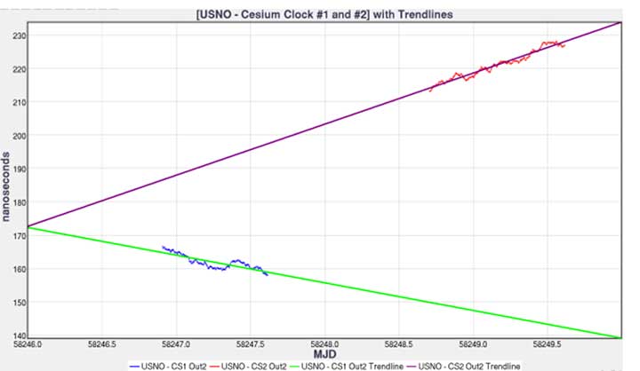
Measurements were further complicated by the delicate nature of cesium clocks, which perform best under finely controlled laboratory conditions. Each cesium reference exhibits its own characteristics that must be observed, measured, and accounted for. Moreover, transporting them to White Sands Missile Range for this test where temperature fluctuations, moving vehicle vibrations, and altitude variations among devices were introduced made synchronization of these clocks particularly challenging. For example, USNO discovered that the Cesium Clock #1 had its internal batteries disconnected — possibly through the original shipment to White Sands, the constant vehicle vibrations while driving on the range, a faulty wiring in the battery terminals, or possibly a combination of all. This problem induced a random offset in the clock, and calibration had to be re-accomplished to reestablish traceability back to UTC (USNO).
Figure 7 shows each cesium clock’s measured drift rate in nanoseconds/second and its corresponding linear fit. This trendline can then be used to project cesium clock #2 to the past and compare it to the measurements of cesium clock #1.
Figure 7. USNO cesium clocks with trendlines. (Image: Author)
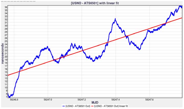
Figure 8 shows the relationship between the timing receiver and USNO master clock and its linear fit. Performing linear fit approximations of the cesium clocks likely introduced unknown errors, potentially increasing the variance of the 1 pps differences.
Figure 8. USNO versus timing receiver with linear fit. (Image: Author)
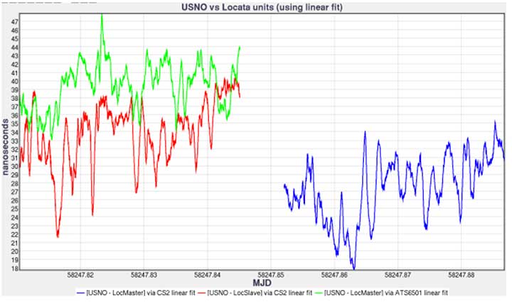
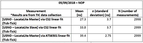
Comparing the 1 pps outputs of the LocataLite master and collocated LocataLite slave to the master site reference clocks (CS2 or timing receiver 1 pps out), the data is traceable back to USNO using the linear fits found for both the USNO timing receiver and cesium clock #2 (Figure 9).
Figure 9. USNO compared to Locata system for May 9, 2018, time interval counter measurements. (Image: Author)
LocataLite timing measurement bias was within 40 ns, and the stability was within 3.7 ns of the reference clocks (see Table 1). The stability of the system is encouraging, as the mean offset can be driven down by more precise measurements and more precise calibrations such as using a two-way satellite time-transfer calibration method (TWSTT).
Table 1. USNO compared to Locata system tabulated values and statistics. (Image: Author)
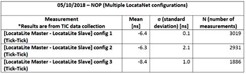
In Table 2, we compare measured data of the 1 pps outputs of the LocataLite master to the collocated LocataLite slave and compute the Locata network internal synchronization in each of the network configurations tested. The data reveals that the network synchronization accuracy is ≤ 2.1 ns. Unfortunately, during Configuration 2 testing, which propagated the TimeLoc signal from NOP to Gran-Jean and back (a total distance of 58.40 km), a technician inadvertently obstructed line-of-site between Locata antennas and consequently temporarily disturbed TimeLoc. Those data points were not removed before this analysis, which is why the reported standard deviation in that configuration, although quite good at 2.1 ns, is nevertheless uncharacteristically high.
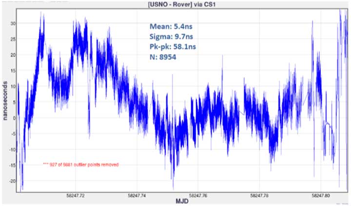
Finally, Figure 10 shows the timing measurements between the USNO master clock and the mobile Locata Rover, via the cesium clock #1 linear fit. Unlike in the LocataLite tests, the Rover is not TimeLoc’d to the network. Instead, it simply calculates its time from LocataLite signals within its line of sight, similar to how a GPS device will calculate its time from satellite signals. During this test, the Rover’s calculated timing accuracy showed a mean of 5.4 ns and stability within 9.7 ns of the USNO master clock, while driving all over the northern portion of the range. To produce the plot, 927 outliers were removed (3 sigma). The outliers occurred at the beginning and ending of the test, when the vehicle was moving from its parking location at Stallion Range Center (outside the operational LocataNet) to the test route and back. The buildings in the area obstructed line of sight and induced significant multipath, which degraded the Rover’s calculations.
Figure 10. USNO LocataLite Rover via CS1 linear fit. (Image: Author)
Conclusion
This endeavor for USNO to characterize the 746 TS NGBPS was met with many challenges, which emphasize the real-world difficulty of measuring time at these extremely fine levels in the field using atomic clocks. The USNO found that some non-linearity started occurring in the USNO – Cesium Clock #2 measurements because of the container of Cesium Clock #2 not being ideal for temperature stability. They also discovered that Cesium Clock #1 had its internal batteries disconnected due to an unknown cause. However, because of deliberate measurements between Cesium Clock #1 and Cesium Clock #2, the USNO was still able to provide calibration measurements but with degradation in the measurement clarity.
From the data collected, USNO personnel found:
The GPS timing receiver at NOP produced 1 pps timing accuracy consistent with its 15-ns RMS specification. Therefore, the reference time delivered to the Master LocataLite was synchronized to UTC within 15 ns.
A standard deviation measurement from Master LocataLite to UTC of under 4 ns.
Locata’s master-to-slave internal time synchronization (independent of GPS) was measured to be between 100 ps and 2.1 ns in 3 different Locata network configurations spanning distances up to 73.84 km (45.88 miles).
The timing measurements in the mobile Rover test show its ability to provide accurate time with a standard deviation of around 10 ns.
Many lessons learned throughout this experiment could be implemented to get more accurate measurements, especially when looking at the accuracies of the GPS time transfer throughout the NGBPS. Looking ahead, more accurate calibration values for both the GPS timing receiver and the Master LocataLite could be made by using a TWSTT method. This would simplify the number of measurements and provide a 1 pps signal of USNO’s master clock, resulting in up to 1 ns of accuracy in the reference time delivered to the Master LocataLite. Depending on the requirements of customers needing NGBPS time at White Sands, the 746 TS and USNO can potentially recharacterize the NGBPS timing accuracy and stability using this methodology.
Manufacturers
The LocataLites and Rovers that create much of the 746 TS NGBPS are manufactured by Locata Corp. The NGBPS synchronized to GPS time via a Microsemi ATS6501 timing receiver. The cesium clocks were Hewlett-Packard 5071A cesium primary frequency standard devices. The USNO used a Novatel ProPak3 for correction data, measured using a Keysight 53230A time interval counter.
Christopher Black earned a B.S. and M.S. in electrical and computer engineering from New Mexico State University. In November 2017 he joined the 746th Test Squadron, Holloman Air Force Base, as a navigation warfare analyst. Now, as lead reference engineer, he heads up research, development and maintenance of the squadron’s reference systems, including UHARS.
This article has been approved by the USAF for public release, #AEDC2019-205.
A FreeFlight Systems SBAS/GNSS receiver has been selected to provide ADS-B position source information as a part of an upcoming ADS-B modification and compliance program for the United States Air Force HH-60G helicopter fleet.
Strategic Enterprise Solutions Corp. (SESC) of Warner Robins, Georgia, was awarded the modification program, which includes installation of the 1203C SBAS/GNSS receiver and the AN/APX-119 Mode S Extended Squitter transponder with Mode 5 capability to provide a complete ADS-B Out solution for more than 100 helicopters.
An HH-60 Pave Hawk helicopter lands in Afghanistan; a UH-60 Blackhawk is in the background. (Photo: U.S. Air Force photo/Senior Airman Brian Ferguson)
The FreeFlight Systems 1203C SBAS/GNSS receiver is a certified, high-integrity position source in a compact, lightweight package that was designed to be modular and able to be integrated with various other avionics.
The 1203C pairs seamlessly with certified Mode S Extended Squitter transponders for a fully rule-compliant ADS-B Out system, FreeFlight said.
More than a war hawk. The primary mission of the HH-60G Pave Hawk helicopter is to conduct day or night personnel recovery operations into hostile environments to recover isolated personnel during war.
The HH-60G is also tasked to perform military operations other than war, including civil search and rescue, medical evacuation, disaster response, humanitarian assistance, security cooperation/aviation advisory, NASA space flight support, and rescue command and control.
The 1203C in service. With several hundred 1203Cs in service across airline transport, military, business aviation and rotorcraft platforms, these receivers are known for their high performance, ease of installation, operational reliability and longevity, FreeFlight said.
The 1203C SBAS/GNSS receiver and antenna (Photo: FreeFlight Systems)
The 1203C can also serve as the approved position source for select manufacturers of TAWS/FMS, RNP and other NextGen applications, and allows customers to take advantage of the operational and safety benefits provided by the NextGen airspace transformation without the need for extensive and costly avionics upgrades.
With the ADS-B mandate now only 17 months away, aircraft operators need to prioritize ADS-B installations.
Significant portions of today’s airline, business, and military aircraft fleet will remain in service long after 2020, and in many cases an STC’d retrofit solution comprising of a transponder upgrade and the addition of a dedicated SBAS/GNSS receiver like the 1203C is the simplest and most cost-effective way to achieve mandate compliance, FreeFlight said.
The U.S. Air Force has awarded a GPS III satellite launch contract to SpaceX. This is the third GPS III launch contract awarded; the previous two also were awarded to SpaceX.
SpaceX will receive a $290,594,130 firm-fixed-price contract for launch services to deliver three GPS III missions (1 base and 2 options) to the intended orbit using two Evolved Expendable Launch Vehicles (EELVs).
A SpaceX Falcon 9 rocket lifts off from Space Launch Complex 4E at Vandenberg Air Force Base, California, Jan. 14, 2017. (Photo: SpaceX)
The launch contract provides the government with a total launch solution for the GPS III mission, including launch vehicle production, mission integration, launch operations and spaceflight certification. The launches will take place from Cape Canaveral Air Force Station or Kennedy Space Center, Florida.
The GPS III missions are planned to launch between late 2019 and 2020.
“The three GPS III missions will deliver sustained, reliable GPS capabilities to America’s warfighters, our allies and civil users,” the U.S. Air Force said in a statement. GPS provides positioning, navigation and timing service to civil and military users worldwide.
In a second launch services contract, United Launch Alliance has been awarded a $351,839,510 firm-fixed-price contract for launch services to deliver Air Force Space Command (AFSPC)-8 and AFSPC-12 satellites to the intended orbit.
This is the fourth competition under the current Phase 1A procurement strategy. Both launch service contract awards strike a balance between meeting operational needs and lowering launch costs through reintroducing competition for National Security Space missions, according to Los Angeles Air Force Base, which made the announcement.
“The competitive award of these two EELV launch service contracts directly supports Space and Missile Systems Center’s mission of delivering resilient and affordable space capabilities to our nation while maintaining assured access to space,” said Lt. Gen. John F. Thompson, U.S. Air Force Program Executive Officer for Space and SMC commander.
SpaceX won two previous GPS III launch contracts, one awarded in March 2017 and one in April 2016.
The GPS Operational Control System’s launch and checkout system will control launch and early orbit operations and the on-orbit checkout of all GPS III satellites. (Image: Raytheon)
The Space and Missile Systems Center announced that the United States Air Force has accepted delivery of the GPS Next Generation Operational Control System (GPS OCX) Launch and Checkout System (LCS) baseline from Raytheon Intelligence and Information Systems.
Also known as Block 0, LCS demonstrated conformance through test and analysis with all contractual requirements. OCX Block 0 is the foundation for Raytheon’s future Block 1 and 2 delivery, slated for delivery in 2022.
LCS is a fully modernized cyber-secure ground system complete with the computing hardware, operations center workstations, and mission application software necessary to launch the first GPS III satellite into orbit and perform initial on-orbit testing.
LCS forms the basis for the full system delivery, referred to as Block 1, which will provide higher accuracy and globally deployed modernized receivers, to ensure anti-jam capability for military users. It will also provide control of both legacy and modernized satellites and signals, including the new international L1C and modernized Military Code.
Currently, mission operators are utilizing LCS as part of the GPS III Mission Readiness Campaign. The ground system is performing as expected during the rehearsals and space vehicle checkout, giving the Air Force confidence in its readiness to support launch and on-orbit operations.
OCX has had numerous challenges delaying the delivery of this critical capability, and this delivery marks a significant program milestone providing the Air Force with a cyber-hardened ground system to support the launch and on-orbit checkout of the GPS III satellites.
“This is a major milestone for the program, and it keeps the U.S. Air Force on track to launch the first modernized GPS satellite into space next year,” said Dave Wajsgras, president of Raytheon Intelligence, Information and Services. “We have strong forward momentum on the program, and we will deliver the full capability in 2021.”
The first launch of a GPS III satellite is scheduled for 2018.
A SpaceX Falcon 9 stands ready for launch from Cape Canaveral Air Force Station, Fla. The Air Force awarded a second contract for GPS III Launch Services to SpaceX.
SpaceX has won a second contract from the U.S. Air Force for launch services to deliver a GPS III satellite to its intended orbit.
SpaceX was awarded the $96,500,490 firm-fixed-price contract over the United Launch Alliance. ULA — a joint venture of Lockheed Martin Space Systems and Boeing Defense, Space & Security — did not compete for the first GPS III launch contract. That contract, worth $82.7 million, is expected to orbit a GPS satellite aboard a Falcon 9 rocket in May 2018.
According to the contract announcement, SpaceX will provide launch vehicle production, mission integration, launch operations, spaceflight worthiness and mission unique activities for a GPS III mission. The contract is being overseen by the Air Force’s Space and Missile Systems Center (SMC), Los Angeles Air Force Base, California.
Work will be performed at Hawthorne, California; Cape Canaveral Air Force Station, Florida; and McGregor, Texas. It is expected to be complete by April 30, 2019.
“The competitive award of the GPS III Launch Services contract to SpaceX directly supports SMC’s mission of delivering resilient and affordable space capabilities to our nation,” said Lt. Gen. Samuel Greaves, leader of SMC.
Beginning Wednesday, Jan. 25, Air Force Space Command (AFSPC) will conduct a limited-duration test implementing an increase of the Ll C/A power level on the GPS Block IIR-M and llF satellites — a total of 19 satellites.
The C/A power will remain within IS-GPS-200-H specifications, and the power increase is not expected to increase the noise floor by more than 0.3 signal-to-noise ratio in the worst case.
“We assess that there will be no adverse impacts to civil, commercial or military GPS users, but anyone who experiences issues during this test should address them through established reporting channels,” said Gen. John W. Raymond, U. S. Air Force (USAF) commander, in a “Memorandum for Distribution.”
Military users can contact the GPS Operations Center at DSN 560-2541, while civilian users can contact the U.S. Coast Guard Navigation Center at 703-313-5900. In the event of unexpected critical impacts, a process to cease testing operations has been put in place.
The AFSPC point of contact for this test is Maj. Jeffrey Koch, DSN 692-0233, commercial 719-554-0233.
The U.S. Air Force approved Lockheed Martin’s design to upgrade the current GPS satellite ground control system with new capabilities that will enable it to operate more powerful and accurate GPS III satellites.
The successful Critical Design Review (CDR) for the Contingency Operations (COps) contract, completed on Nov. 17, gives Lockheed Martin a green light to proceed with software development and systems engineering to modify the existing GPS ground control system, called the Architecture Evolution Plan (AEP) Operational Control Segment.
SV 01 in testing at Lockheed Martin’s Denver facility. (Photo: LMCO)
The AEP is currently maintained by Lockheed Martin and controls the 31 GPS IIR, IIR-M and IIF satellites in orbit today.
The COps modifications will allow the AEP to support the more powerful, next generation GPS Block III satellites, enabling them to perform their positioning, navigation and timing mission, once they are launched. COps is envisioned as a temporary gap filler prior to the entire GPS constellation’s transition to operations onto the next generation Operational Control System (OCX) Block 1, currently in development.
“The GPS constellation is a valuable asset to our warfighters, our nation and the world. This risk-reduction effort ensures the Air Force has the ability to maintain the constellation at full strength,” said Mark Stewart, vice president of Lockheed Martin’s Navigation Systems mission area. “We are here to support the Air Force and the GPS III program any way we can.”
The Air Force awarded the $96 million COps services and supplies contract to Lockheed Martin on February 3. The government approved the company’s proposed ground system modification during a Preliminary Design Review on May 11.
On Oct. 15, under a separate contract, Lockheed Martin completed the Commercial Off-the-Shelf (COTS) Upgrade #2 (CUP2) project — part of a multi-year plan to refresh the AEP’s technology and enhance the system’s ability to protect data and infrastructure from internal and external cyber threats, as well as improve its overall sustainability and operability. CUP2 is now fully operational and managing the current GPS constellation.
Lockheed Martin has a long history of supporting ground systems, providing operations, sustainment and logistics support for nearly 60 Department of Defense satellites, including GPS, often allowing them to double their on-orbit operational design life.
Lockheed Martin also is under contract to develop and build the Air Force’s first ten GPS III satellites, which will deliver three times better accuracy, provide up to eight times improved anti-jamming capabilities and extend spacecraft life to 15 years, 25 percent longer than the newest GPS satellites on-orbit today.
GPS III’s new L1C civil signal also will make it the first GPS satellite to be interoperable with other international global navigation satellite systems.
Non-GPS positioning system, White Sands North Range. X = transmitter site. (Photo: U.S. Air force, 746 Test Squadron)
Can’t Deny the Truth: Defeating the Jamming Threat
Initial Operational Capability for the Ultra High-Accuracy Reference System has been declared by the U.S. Air Force. Even when GPS is being completely jammed, UHARS provides extremely accurate positioning, navigation and time — more accurate than GPS — over the large area of White Sands Missile Range in New Mexico.
Amid a growing concern about GPS jamming in military areas of operation, testing GPS receivers and antenna systems in a GPS-denied environment has become increasingly important to Department of Defense (DoD) agencies. However, since GPS is often the “gold standard” position, navigation and time information that serves as a truth reference during field and flight testing, conducting tests in an area that has no GPS availability because of intense jamming makes it difficult to compare observed position and navigation data to a valid truth source. Moreover, to evaluate system performance with appropriate statistical significance, the reference system against which test results are measured needs to be significantly more accurate than the system under test. Therefore, when the system under test is GPS itself, this poses an interesting problem.
FIGURE 1: CIGTF Reference System (CRS) (Photo: U.S. Air force, 746 Test Squadron)
For more than a decade, the 746th Test Squadron (746 TS), also known as the Central Inertial and GPS Test Facility (CIGTF), has met this requirement by employing its CIGTF Reference System (CRS). The CRS (Figure 1) is a system of navigation sensors that evaluates combinations of its subsystem measurements in an extended Kalman filter/smoother algorithm to produce an optimal reference trajectory. Delivering sub-meter accuracy in non-GPS-jammed environments and meter-level accuracy in GPS-jammed environments, the CRS is arguably the most accurate reference system in the DoD. However, many future DoD weapons systems are projected to require tighter navigation accuracies in GPS-denied environments, and as these requirements improve, the reference system against which they are evaluated must improve accordingly. To meet these test and evaluation reference requirements in a GPS-denied environment, a new reference system is needed.
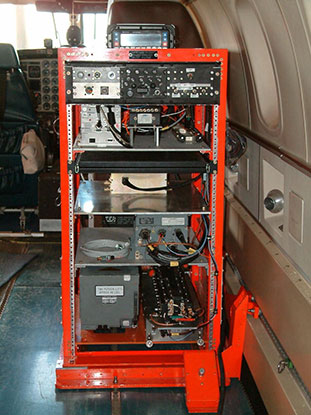
The 746 TS embarked on the development of the Ultra High Accuracy Reference System (UHARS), a next generation reference system that meets test and evaluation reference requirements for future navigation and guidance systems. UHARS consists of a rack-mounted, tightly integrated system of improved navigation sensors/subsystems, data acquisition system (DAS) and a new post-mission reference trajectory algorithm. The complete system will provide a significantly more accurate reference solution for future airborne and land-based test vehicles in navigation warfare environments where modernized and legacy GPS signals are jammed from friendly or hostile systems.
Non-GPS Based. Achieving these accurate reference solutions requires a Non-GPS Based Positioning System (NGBPS) subsystem capable of operating and providing sub-meter position accuracy in a GPS-denied (jamming) environment. The NGBPS portion of the UHARS program employs a network of ground-based LocataLite transceivers and test vehicle receivers (also called rovers). Although the NGBPS uses standard commercial LocataLites and rovers, meeting the demanding UHARS accuracy and distance requirements of better than 18 centimeters accuracy over a 30-mile range in a flight configuration necessitated some additional testing and development of transmit antennas, external signal amplification, navigational software for flight dynamics, as well as the addition of a centralized command and control (C2) capability so the network could be remotely controlled, across the range, from the 746 TS building at Holloman Air Force Base.
Background
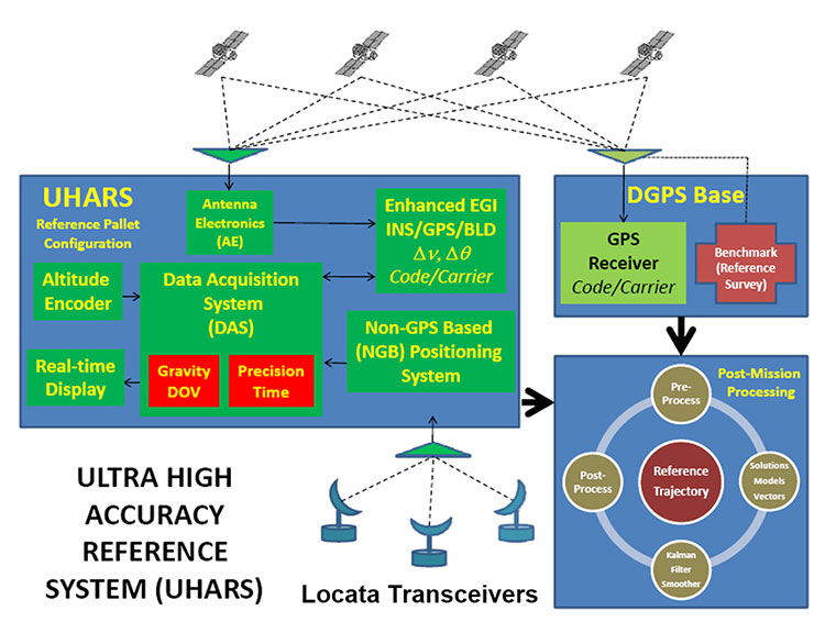
FIGURE 2: UHARS architecture. (Photo: U.S. Air force, 746 Test Squadron)
The UHARS architecture (Figure 2) is comprised of three major subsystems which include the Enhanced Embedded GPS/INS (EGI), Locata NGBPS and GPS Antenna with Antenna Electronics (AE). Other key technologies include the DAS, Differential GPS (DGPS) Base Station and Reference Trajectory Algorithm.
The NGBPS rover collects 10.23 MHz chipped code pseudorange and carrier-phase measurements at selectable rates of 1, 5 and 10 Hz. The system uses a patented timing process which tightly synchronizes all LocataLites in the network. With this done, data from the Locata test bed receiver can be processed exactly like survey-grade GPS measurements, but without the need for differential corrections.
Each LocataLite transmits on two spatially diverse signals from two separate antennas at two frequencies within the 2.4-GHz industrial, scientific and medical (ISM) frequency band, 2434.740 MHz and 2462.361 MHz, for a total of four spatially and frequency diverse signals. That signal structure provides precise positioning signals that are both resistant to GPS L1 and L2 jamming and also provide highly accurate positioning.
Overview
FIGURE 3: Locata solar aluminum transportable trailer (LSATT). (Photo: U.S. Air force, 746 Test Squadron)
The deployed system includes 16 Locata Solar Aluminum Transportable Trailers (LSATT) with flexible power options that integrate both shore power (110V AC) and reusable solar power (Figure 3). The trailer configuration enables easy transportation of major NGBPS components on and off WSMR, allowing for easy reconfiguration of the network or deployment to other test ranges if required.
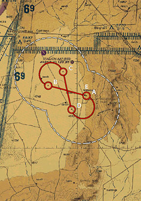
The NGBPS design currently includes 20 geographically separated deployment sites, 16 of which are populated with LocataLites, over a 20 x 20 mile area on WSMR North Range (see opening figure). This configuration can be scaled to cover an even larger area when required.
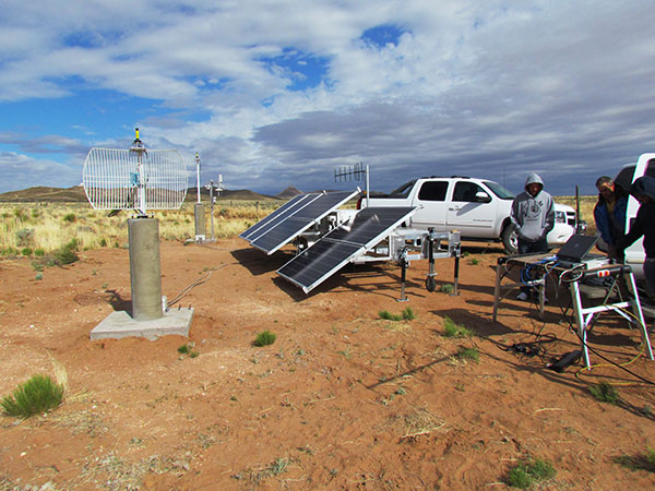
FIGURE 4. NGBPS transmitter site. (Photo: U.S. Air force, 746 Test Squadron)
Each site contains permanent monumentation for the two spatially diverse transmit antennas (two monuments per site; 40 total). Figure 4 shows a typical monument site which is equipped with a quadrifilar helix S-band transmit antenna, and one monument also supports the 2.4-GHz receive dish antenna. The monuments and antennas are integrated with an LSATT, UHF-band (350-360 MHz) wireless architecture for the command and control element, and a meteorological (MET) station made by Vaisala. The MET station measures and collects temperature, pressure and relative humidity data,for calculating tropospheric corrections which are then transmitted as part of the positioning signal generated by a LocataLite for use across the network.
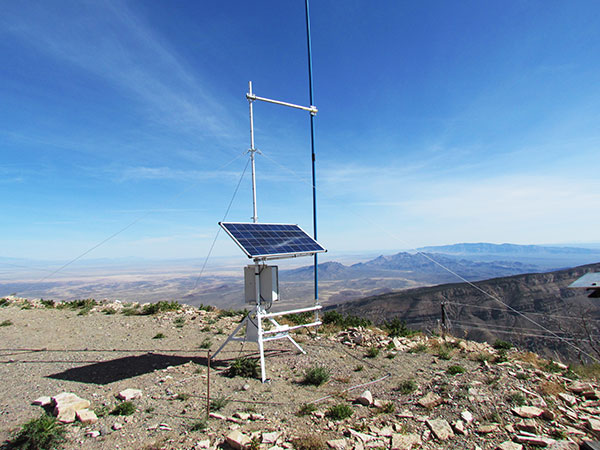
FIGURE 5: NGBPS C2 repeater station. (Photo: U.S. Air force, 746 Test Squadron)
The system is operated, controlled and monitored using either the fixed C2 center located at the 746 TS, Holloman AFB, NM or the mobile C2 Center. The mobile C2 is typically located on the WSMR-North Range to support test events. Two repeater stations (Figure 5) are installed at WSMR-North Range to enable long distance remote/wireless C2 communications with the NGBPS network.
Site Architecture
The LSATT includes integrated hardware and software to produce the NGBPS network. The heart of the NGBPS is the LocataLite transceiver, which provides the ranging signals used by the rover to compute position and time information. The same signals are used by each LocataLite for nanosecond-level synchronization across the network. The MET station, mounted on monumentation along with a transmit antenna, collects temperature, pressure and relative humidity data and relays it to the LocataLite for inclusion in the transmitted navigation signal. The LocataLite provides the exciter signal to two Mini-Circuits amplifiers which boost the RF power to around 10 watts for each transmit antenna, providing signal coverage over the large geographical area of WSMR-North Range. The wireless modem relays Locata and MET data to and from the C2 centers using various package compression techniques to ensure data are not lost during transmission. The modem provides 4 watts of power operating in the UHF-Band with a directional high gain antenna.
Situated in the New Mexico desert, the LSATT is also required to operate during extreme weather conditions, necessitating the employment of water-tight containers and temperature reducing mechanisms to protect its commercial subsystems. Accordingly, a filtered fan configuration mitigates elevated temperatures during operation.
Each LSATT also possesses an intelligent low power controller that supports the various communication protocols within the equipment enclosure. A comprehensive and expandable feature of the controller design enables a centralized methodology for data collection, health and status information and C2 functions. The controller interfaces with the LocataLite transceiver, MET station, amplifiers, and power supply sources. Information is collected and packetized for efficient transmission via the wireless modem. Commands from the fixed or mobile C2 center are received and implemented by the controller. During non-operating periods, the controller reduces power consumption by shutting down non-essential equipment. Likewise, the controller itself enters a stand-by mode until reactivated by the C2 center via the wireless modem. The controller provides a redundant data archive capability and autonomously manages operations in the unlikely event of a wireless communication outage with the C2 Centers. The controller is programmed to shut down after a definable period if C2 communication links cannot be re-established.
The NGBPS design provides pre-, live- and post-mission support through remote wireless C2 operations. This support includes real-time status monitoring and a net-centric architecture for C2 of remote locations. As C2 outages are detected, the wireless network autonomously attempts to self-repair and return the network to an operational state.
Verification and Validation
FIGURE 6: A typical NGBPS clear air flight profile. (Photo: U.S. Air force, 746 Test Squadron)
After all network and C2 software activities had been completed, TMC Design Corporation conducted a Final System Verification (FSV) on the fully fielded NGBPS system on WSMR. The FSV ensured all contractual requirements were adequately met prior to release to the 746 TS for government operations. It included verifying successful communication through the UHF network and ensured that the rover could obtain and process information from each LSATT site in view. Additionally, a mission duration test was performed to ensure the system could operate for the period of a standard mission window without depleting the battery system.
Upon completion of the FSV in September 2014, the 746 TS conducted a series of flight tests to:
Measure the NGBPS PDOP over the WSMR fielded area.
Compare the measured PDOP values to the developed PDOP model.
Evaluate carrier-phase solution with an objective accuracy of
FIGURE 7: USAF C-12J aircraft fitted with Locata antenna. (Photo: U.S. Air force, 746 Test Squadron)
Once the squadron’s PDOP model was verified, flight profiles were carefully devised to stay within the NGBPS PDOP < 3 envelope (Figure 6). However, since the 746 TS also sought to evaluate other UHARS components, both individually and as a system, additional flight profiles were flown. When these flight profiles happened to meet NGBPS PDOP criteria, performance was recorded and analyzed. All flight profiles were flown at varying altitudes, aircraft speed and time of day in order to test the NGBPS network performance under a wide range of scenarios.
Although an operational UHARS will ultimately provide an exceptional reference solution in a GPS-denied environment, GPS signals needed to be available during NGBPS validation in order to evaluate the Locata navigation carrier-phase solution against a Differential GPS carrier-phase solution. Thus, all NGBPS validation testing was conducted in clear, unjammed environments. Now that system performance is verified in this NGBPS configuration, it can be used as the primary source of positioning when the GPS signals are denied.
Flight trials were conducted using the USAF C-12J aircraft (Figure 7) integrated with one quadrifilar helix S-band receive antenna. The NGBPS receiver was integrated in the UHARS flight pallet, and a DAS was connected to the receiver to log specific receiver and health data required for post-test data analysis.
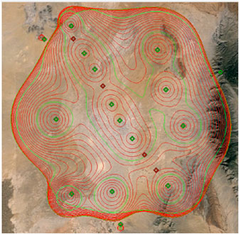
FIGURE 8: NGBPS PDOP plot. (Photo: U.S. Air force, 746 Test Squadron)
Figure 8 illustrates the top-down view of the predicted PDOP=3 boundaries across the NGBPS network on WSMR. The PDOP volume coverage is shown in 1000 ft. increments (red lines) from 5K to 30K ft. MSL. The green lines are at 10K, 20K and 30K ft. The flight profiles were flown within the PDOP volume footprint to obtain carrier-phase solutions.
Results
The 746 TS conducted extensive flight tests where the NGBPS system was tested under operationally realistic conditions. Preliminary test results have proven good enough to declare Initial Operational Capability (IOC) for use by the 746 TS’s many DoD and Government customers. Not only does the network deliver centimeter-level positioning and navigation, but also nanosecond-level synchronization, which may be useful for military applications requiring precise time transfer in GPS-denied environments. Working in concert with other UHARS components, the LocataNet supports a reference solution which outperforms the CRS in GPS-denied environments.
“Initial testing shows that UHARS delivers accurate independent PNT as good as, or better than, the USAF’s current CRS, so it is perfectly able to support current customer requirements,” said Jim Brewer, chief scientist of the 746 TS. “However, more data are required to tune the UHARS filter and optimize its accuracy to meet even tighter PNT requirements, which is our objective. When this is achieved, UHARS will deliver truth accuracy for next-generation military capabilities, and we will declare UHARS at Full Operational Capability.”
“UHARS is a rack-mounted, tightly integrated system of improved navigation sensors, a data acquisition system and a new post-mission Kalman filter, all of which need to work together,” explained John Cao, technical director of the 746 TS. “It’s working very well, but once we completely measure and characterize the individual components and then tune and validate the filter, the complete system will provide a significantly more accurate reference solution for future airborne and land-based test vehicles in navigation warfare environments where modernized and legacy GPS signals are jammed from friendly or hostile systems.”
Summary & Conclusions
As designed, deployed, and validated, this tailored network provides accurate 3D positioning, completely independent of GPS and while traveling in a dynamic aircraft flight profile. This enables the US government to test, evaluate, and assess capabilities in GPS-denied environments.
Based on successful results of the original technical demonstration at WSMR in a real-world end-to-end environment, the USAF proceeded to the NGBPS production and fielding phase in 2012.
The currently installed network infrastructure on WSMR includes 20 permanent monument sites, 16 LSATT trailers installed in select initial site locations, comprehensive C2 software and solar and battery power for all sites. The system is self-contained, remotely operated and possesses high quality, reliability and safe operation attributes. Its NGBPS capability is now core to the UHARS that is replacing the CRS.
Initial testing shows that UHARS delivers accurate independent PNT as good as, or better than, the USAF’s current CRS truth system, and the 746 TS has therefore declared Initial Operational Capability (IOC) for UHARS, making it immediately available to support customers requiring an accurate non-GPS-based solution. Further verification testing will enable the squadron to fine tune the UHARS filter and optimize its accuracy even further to meet even tighter PNT requirements. At that time UHARS Full Operational Capability (FOC) will be declared.
Customers interested in leveraging UHARS into their test programs should contact the 746 TS at (575) 679-2123 or [email protected] for scheduling information.
Manufacturers
LocataLites, Locata rovers and the software/firmware that enables the TimeLoc synchronization technology which creates the LocataNet are manufactured and supplied by Locata Corporation. The S-band transmit antenna was made by Cooper Antennas Ltd.
The 746 TS awarded two separate sole-source contracts for NGBPS. The Locata Corporation was contracted to provide production transceivers and rovers, navigation algorithms required for data analysis and subject matter expertise. The TMC Design Corporation was contracted to develop the hardware to house and field the Locata network, develop the command and control hardware and software, and then physically field the production hardware at WSMR.
KEY NGBPS requirements
After successful completion of the technical demonstration in 2011, in which all of these key technical requirements were demonstrated, the USAF awarded contracts to field the NGBPS.
Carrier-phase “truth-reference” solution of < 18 cm Three Dimensional Root Mean Square (3dRMS), with a Position Dilution of Precision (PDOP) < 3.0.
Rover receivers acquiring and tracking Locata signals at a range greater than 30 miles (48 km).
Accurate and reliable TimeLoc synchronization over the test area, the ability to “cascade” TimeLoc from one LocataLite to another, plus the delivery of nanosecond-level synchronized time on the Range while GPS time is unavailable because of GPS jamming.
External signal amplification to support the extended signal range requirement while still maintaining nanosecond-level TimeLoc integrity.
Rover receiver tracking loops perform adequately under flight dynamics.
Tropospheric measurement and modeling to ameliorate the large tropospheric errors (approximately 300 ppm uncorrected) experienced by terrestrial signals at these ranges.
Transmit and receive antennas that provide both adequate gain and multipath mitigation for an aircraft flight scenario.
How many times have you heard of a nearly 20-year-old space constellation being modified with a new technology? It almost never happens.
I will never forget when the general slid the sensitive Iridium folder across my desk; I knew from his facial expression that he was not happy. The folder contained a controversial civilian plan to de-orbit the entire multi-billion dollar Iridium communications satellite constellation less than a year after it was launched.
Fortunately, the folder also contained a proposed military, U.S. government (USG) and joint civilian proposal to sustain the constellation, with the only caveats being that a buyer be found and that the military and/or USG provide “indemnity” (insurance policy) for the Iridium constellation if it were to be utilized by the USG and our Allies, especially during wartime. At the time I was serving as the deputy chief scientist at Air Force Space Command headquarters. Our job was to determine the technical feasibility of both proposals and make a recommendation.
Iridium satellites
Replica of Iridium satellite. (Photo courtesy of Iridium)
Launched in 1998 by Motorola, Iridium is a satellite communications constellation that is a “technological marvel,” as John Bloom writes in his new book about Iridium, Eccentric Orbits. Additionally, Iridium was and remains a capability sorely needed by the USG that in many ways revolutionized global communications — unfortunately, just not in the manner or time frame Motorola originally envisioned.
Indeed, eventually not 66 or 77, or even 88, Iridium satellites would be launched, as you will read in many places. Rather, a total of 95 Iridium satellites have been launched to date, which should give the constellation the name Americium, since 95 is the atomic number for the element americium. But I digress.
The problem with Iridium was not technical or even space-related. Motorola, which developed the technology and launched the constellation into low Earth orbit (LEO) — an amazing feat in so many respects — totally missed the correct marketing strategy. Motorola developed Iridium as a quick (five-year lifetime) money-making capability and profit center when in fact it proved to be a much longer term project. Today, there are Iridium satellites that are fully expected to be on orbit and fully functioning for more than 20 years.
The original Iridium satellite was — and still is — a technological marvel that broke almost all the so-called rules for manufacturing spacecraft:
The satellites were built without any fully space qualified or certified parts.
The satellites were not built in a clean room.
The satellites were built “horizontally” on a moving assembly line, like automobiles, versus vertically, individually and historically as a stationery static device. The moving assembly line produced a satellite every five days by a little-known company that eventually became part of Lockheed Martin (LMCO).
The satellites were launched by nearly every space-faring nation that had a launch capability at the time.
The original Iridium satellites were built for a projected lifetime of five years — that was more than 18 years ago. The current Iridium constellation of 66-plus satellites (remember, 95 have been launched) has exceeded its projected lifetime by nearly 400 percent, and is still going strong.
In 2010, Iridium Communications entered into a long-term agreement with Boeing for maintenance, operations and support of the satellite network. Boeing operates the constellation and provides support for Iridium’s satellite control system (SCS).
How many times have you heard of an almost 20-year-old space constellation being modified with a new technology? It almost never happens.
The constellation’s legacy
Amazingly, the only reason the Iridium constellation still exists today, in several respects, is due to the intervention of the USG and a major program that suffered a production failure. Originally Motorola contracted for an additional hosted payload that just never came to fruition. The nameless company developed an Iridium test program, on which it failed to deliver. This “major glitch” caused a weight and balance problem for the Iridium satellites, which Danny Stamp, an Iridium program engineer, solved at the time by recommending a quick fix: adding an additional fuel load of the same weight as the failed payload to the satellite. It was a simple fix just to get the satellites launched on time that no one thought much about at the time. However, the result was a key component — remaining or residual fuel — that ensures the satellites are still in orbit, and can be maneuvered and working properly today.
As I mentioned earlier, one of the major reasons the entire Iridium constellation was not de-orbited was because the USG decided it was a necessary tactical capability during wartime for our warfighters, as well as being an amazing R&R tool for morale purposes. (The Iridium system enabled conversations with loved ones back home.)
Add to that a civilian plan put together by some true visionaries, individuals such as Dan Colussy and corporate partners such as Boeing, that were able to purchase the entire constellation for pennies on the dollar, and you have an incredible success story.
The result is one of the most successful — certainly the largest and most well known — satellite communication constellations ever flown. Plus, as I mentioned earlier, Iridium has proposed a brand-new capability that, if it comes to fruition, has the potential be a huge boon for GPS by serving as a key global PNT augmentation.
The way ahead
Just last week, Iridium announced that it is proposing, or has developed, in conjunction with other companies, an augmentation or compliment to GPS. Reuters quoted the CEO of Iridium Communications, Matthew Desch as saying the new technology used chips that were the size of a postage stamp, and could ultimately be integrated into other devices, heavy machinery, automobiles and the power grid.
The system, known as STL or Iridium Satellite Time and Location System, transmits signals via Iridium’s satellite constellation, delivering codes to ground positions that are independently authenticated, Reuters reported.
Both Iridium and the private firm Satelles said STL as a system has been demonstrated in military, academic and commercial applications. The Reuters article didn’t provide specific details on the exact nature of the devices or any launch customers. (Satelles and Boeing entered into a patent and technology license agreement for STL in 2013).
Iridium NEXT, Iridium’s next-generation global satellite constellation, will support the STL solution. Iridium NEXT is scheduled for completion by late 2017. Along with supporting the current Iridium constellation, Boeing is under contract from prime contractor Thales Alenia Space to provide system integration and testing support for Iridium NEXT.
So, while STL is far from concrete, it makes for an interesting possibility that Iridium is proposing or has apparently built an on-orbit satellite augmentation to GPS, and PNT in general. My government inquires brought the to-be-expected, “We can neither confirm or deny” response. As far as Iridium and Satelles are concerned, I suppose it is a wait-and-see proposal.
Still, it is good to see company internal R&D funding being used to further support our global PNT infrastructure. Now that the word is out, we can look for more details on the horizon. So stay tuned. By the way, many of you may remember that this is not the first time Iridium has gone down this path; perhaps this time it will actually work.
Yes, sometimes 18 years ago seems just like yesterday.
Abstract: The iGPS high-integrity precision navigation system combines carrier-phase ranging measurements from GPS and low-Earth orbit Iridium telecommunication satellites. Large geometry variations generated by fast moving Iridium spacecraft enable the rapid floating estimation of cycle ambiguities. Augmentation of GPS with Iridium satellites also guarantees signal redundancy, which enables fault-detection using carrier phase Receiver Autonomous Integrity Monitoring (RAIM). Over short time periods, the temporal correlation of measurement error sources can be exploited to establish reliable error models, hence relaxing requirements on differential corrections.
In this paper, a new ionospheric error model is derived to account for Iridium satellite signals crossing large sections of the sky within short periods of time. Then, a fixed-interval positioning and cycle ambiguity estimation algorithm is introduced to process Iridium and GPS code and carrier-phase observations. A residual-based carrier phase RAIM detection algorithm is described and evaluated against single-satellite step and ramp-type faults of all magnitudes and start-times. Finally, a sensitivity analysis focused on ionosphere-related system design variables (ionospheric error model parameters, code-carrier divergence, single and dual-frequency implementations) explores the potential of iGPS to fulfill some of the most stringent navigation integrity requirements with coverage at continental scales.
ION Joint Navigation Conference
The highly anticipated and always rewarding Institute of Navigation Joint Navigation Conference (ION JNC) kicks off this week, June 6-9, at the Convention Center in Dayton, Ohio, and at Wright Paterson Air Force Base.
There are the expected technical and joint presentations, along with a classified day (U.S. only) and a Warrior Panel. It all sounds like a great time and an educational experience. Be sure to visit the National Museum of the U.S. Air Force, including the website where you can take a virtual tour; it is an amazing venue. Also take time to visit the Wright Brothers exhibits in the “Birthplace of Aviation” while you are there.
Wright Brothers 1901 Wind Tunnel on display in the Early Years Gallery at the National Museum of the United States Air Force. (Photo: U.S. Air Force)
ION always puts on a great event. I hope many of you are there to participate.
Until next time, happy navigating, and remember: GPS is brought to you free of charge, courtesy of the United States Air Force.
General Atomics Aeronautical Systems Inc. (GA-ASI) has successfully flown the Predator B/MQ-9 Reaper Extended Range (ER) Long Wing craft.
The long-wing Predator is retrofitted with improved long-endurance wings, greater internal fuel capacity and additional hard points for carrying external stores. The flight took place Feb. 18 at GA-ASI’s Gray Butte Flight Test Facility in Palmdale, Calif., on a test aircraft.
GA-ASI is a a manufacturer of remotely piloted aircraft (RPA) systems, radars, and electro-optic and related mission systems solutions.
“Predator B ER’s new 79-foot wing span not only boosts the RPA’s endurance and range, but also serves as proof-of-concept for the next-generation Predator B aircraft that will be designed for Type-Certification and airspace integration,” said Linden Blue, CEO. “The wing was designed to conform to STANAG 4671 [NATO Airworthiness Standard for RPA systems], and includes lightning and bird strike protection, non-destructive testing and advanced composite and adhesive materials for extreme environments.”
During the flight, Predator B ER Long Wing demonstrated its ability to launch, climb to 7,500 feet (initial flight test altitude), complete basic airworthiness maneuvers, and land without incident. A subsequent test program will be conducted to verify full operational capability.
Developed on Internal Research and Development (IRAD) funds, the new wing span is 13 feet longer, increasing the aircraft’s endurance from 27 hours to more than 40 hours.
Additional improvements include short-field takeoff and landing performance and spoilers on the wings that enable precision automatic landings. The wings also have provisions for leading-edge de-ice and integrated low- and high-band RF antennas.
An earlier version of Predator B ER featuring two wing-mounted fuel tanks is currently operational with the U.S. Air Force as MQ-9 Reaper ER.
The long wings are the first components to be produced as part of GA-ASI’s Certifiable Predator B (CPB) development project, which will lead to a certifiable production aircraft in early 2018.
Further hardware and software upgrades planned for CPB will include improved structural fatigue and damage tolerance, more robust flight control software and enhancements allowing operations in adverse weather.