Infleqtion has announced availability of its first quantum-enabled precision timing solution delivered as part of the company’s partnership with Safran Electronics & Defense. The new solution includes Infleqtion’s Tiqker quantum optical clock, which has been integrated and validated with Safran’s White Rabbit and SecureSync systems.
Modern systems, from financial markets to military operations, telecom networks and datacenters, depend on technologies such as GPS or GNSS for precise timing, but these are vulnerable to jamming, spoofing, and natural disruption. As threats to traditional timing infrastructure grow, the need for resilient, independent alternatives has become critical.
In a recent live demonstration conducted in partnership with Quantum Corridor, the solution integrating Tiqker, White Rabbit and SecureSync system was validated in a real-world environment, demonstrating picosecond accuracy vs. nanosecond GPS accuracy.
The combined, validated solution delivers enhanced stability and resilience, ensuring continuity of operations for mission-critical systems even in environments where traditional timing signals are challenged or denied.
The collaboration between Infleqtion and Safran Electronics & Defense makes the validated solution available to customers globally, across allied defense, telecommunications, and critical infrastructure sectors, enabling rapid deployment of precision timing architectures designed to operate even in GNSS-challenged environments.
The Safran Navigation & Timing critical infrastructure solution, White Rabbit, has received high praise in a report published by the European Commission (EC) Joint Research Center (JRC) that evaluates the effectiveness of alternative positioning, navigation and timing (APNT) platforms.
For more than eight months, the commission studied a variety of available solutions to assess the performance of APNT demonstration platforms in a variety of situations where there is signal loss, and a backup system is necessary. The selected solutions were evaluated for precise and robust timing and positioning services in challenging indoor and outdoor environments.
Safran’s White Rabbit is a high-accuracy time and frequency distribution protocol, which combines precise time protocol (PTP) packets with the frequency base of Synchronous Ethernet (SyncE) to provide sub-nanosecond time transfer accuracy over an optical fiber. While the results of the test campaign showed that all APNT platforms under evaluation demonstrated performances in compliance with the requirements set, White Rabbit excelled in its performance.
Safran demonstrated White Rabbit’s ultra-accurate time transfer over fiber optics, its high-performance time generation, resiliency (based on failover and holdover), interoperability, and user-friendly monitoring capabilities.
As stated in the report, Safran demonstrated, “the ability to handle multiple master clock inputs with voting and seamless switchovers. Interconnecting as many NMIs as possible, with possible local atomic clock backups, would result in a very robust and resilient time architecture, independent from GNSS across Europe. The ability to provide resilient and accurate time through the EU communication infrastructure, ideally on the nanosecond level, would also enable robust positioning, using a combination of signals.”
Leveraging Orolia’s HATI core in combination with Arista MetaWatch, the integration provides sub-nanosecond timestamping with accurate, precise and reliable timing
The collaboration between Orolia and Arista sets a new standard in time synchronization for FPGA-based network devices with the support of native White Rabbit capabilities to achieve sub-nanosecond time synchronization using optical fibers across multiple points in the network.
This integration is factory-supported in combination with the MetaWatch application in the Arista 7130LB platform, enabling distributed traffic capture with high-resolution timestamping, buffering and de-duplication, to provide advanced network monitoring and detailed network analytics. Deep buffering, time-ordered aggregation and de-duplication reduce the load on downstream packet capture and analysis devices.
“One key feature of this important collaboration is the simplification of the overall network architecture by eliminating coaxial cabling and PPS distribution equipment,” said Francisco Girela, White Rabbit application engineer with Orolia. “This integrated solution eases the adoption of White Rabbit, leading to cost savings, reduced footprint and better scalability.”
White Rabbit is an ultra-accurate IEEE 1588 Precision Time Protocol (PTP) implementation that achieves sub-nanosecond accuracy over optical fiber links. Designed for use in avionics, telecommunications, space, defense and scientific applications, White Rabbit has become the gold standard for time distribution within electronic trading networks.
Arista’s MetaWatch is a powerful FPGA-based network application designed for Arista’s 7130 platform and combines several components of a traditional network monitoring solution into one device, which simplifies network data capture, monitoring and analytics.
“Moving from analog time synchronization to fiber-based White Rabbit will allow our customers to improve their network analytics while improving the overall synchronization accuracy across a large estate,” said David Snowdon, engineering director, Arista. “The combination of MetaWatch and White Rabbit allows for less than a nanosecond of error on any timestamp taken in a wide-area network — a crucial feature for trading firms optimizing their latency, or for exchanges guaranteeing fairness.”
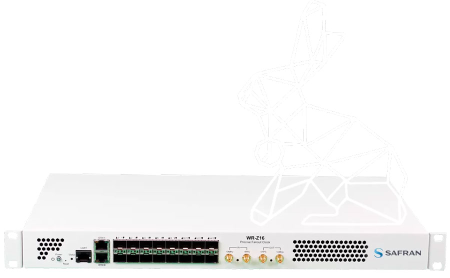
The Orolia White Rabbit Z16. (Photo: Orolia)
Orolia’s WR Z16, a reliable and precise time fan-out solution for White Rabbit distribution on 1G Ethernet-based networks, is a standalone device with 16 SFP connectors that provide sub-nanosecond accuracy over the plug-and-play optical fiber links. The HATI core requires an activation license generated by Orolia to be loaded in the reference WR-Z16 device paired with it to be functional.
Better Performance Combining Fiber Optics and Wideband Radio
Innovation Insights with Richard Langley
“OH DEAR! OH DEAR! I SHALL BE LATE!” That’s what the White Rabbit said in the opening chapter of Lewis Carroll’s Alice’s Adventures in Wonderland just before checking the time on its pocket watch. Scientists at the European Organization for Nuclear Research (known by its French acronym CERN) named their project to develop an Ethernet-based network for general purpose data transfer and sub-nanosecond accuracy time transfer after the time-conscious rabbit. CERN’s White Rabbit (WR) can provide sub-nanosecond accuracy to synchronize more than 1,000 nodes via optical fiber or copper connections of up to 100s of kilometers in length. It is a flexible system with a scalable and modular infrastructure with a simple configuration and low maintenance requirements. It is also open source.
WR uses the IEEE 1588 Precision Time Protocol (PTP) to establish precise phase differences between a master reference clock and a local clock. A two-way exchange of PTP synchronization messages allows precise adjustment of clock phase and offset.
So, what has this got to do with GPS or more generally GNSS? Well, for one thing, a WR-based system can serve as a back-up for GNSS time transfer or even replace GNSS. For example, a multi-hop WR link has been installed to connect financial trading locations in Chicago and New Jersey over an approximately 1,350-kilometer distance. Stock markets and other financial institutions need to time-tag transactions with traceable synchronization to a high-accuracy time standard to the microsecond level or better and a WR link can easily provide that.
Another application of WR is in terrestrial positioning. As we know, one of the problems with GNSS positioning is its poorer performance in built-up areas compared to open ones due to blocked signals and multipath. Multipath signals from close-by reflectors can be particularly pernicious as they reduce pseudorange measurement accuracy and thereby increase position error. And another potential weakness of GNSS is its susceptibility to radio-frequency interference, jamming and spoofing. A positioning system using synchronized roadside radio transmitters could be a viable alternative to GNSS in urban areas. A team of researchers based in The Netherlands has developed just such a system. In this month’s column, they describe their system, which uses WR to synchronize the transmissions of wideband radio ranging signals, and how they are able to achieve decimeter-level position accuracy in multipath environments.
By Cherif Diouf, Han Dun, Gerard Janssen, Erik Dierikx, Jeroen Koelemeij and Christian Tiberius
GPS is undoubtedly the most popular system providing positioning, navigation and timing (PNT) services to a host of applications, industries and infrastructures. GPS is mass-adopted, has worldwide coverage, has an impressive up-time and can be used with a wide range of receiver devices, featuring low to high cost and low to high precision.
Despite its strengths, the system also has some weaknesses. For instance, the positioning performance provided by GPS in dense multipath environments, such as in urban canyons, is poor. This is due to the interaction between the desired line-of-sight (LOS) component and close-in multipath components of the GPS signal reflected or scattered by built-up surroundings. Moreover, GPS signals, due to their low received power levels, are fairly vulnerable to unintentional and intentional threats such as radio-frequency interference, jamming and spoofing.
Alternative solutions that may complement or back up GPS, and more generally any other GNSS, to achieve reliable PNT for critical services and infrastructure, such as first responders, telecommunication and power systems, are urgently sought after. Wide coverage area synchronization using White Rabbit optical fiber networks allows simultaneous Ethernet networking and dissemination of 100 picosecond-level accurate time and frequency signals over distances of hundreds of kilometers. Accurate time synchronization may be provided to large areas such as big cities through this technology.
Building on such an accurate system, we present a concept and demonstration of an innovative hybrid optical-wireless terrestrial networked positioning system (TNPS). The TNPS demonstrator uses a White Rabbit infrastructure to accurately synchronize the transmissions of wideband radio positioning signals by its ground-based transmitters (pseudolites) and achieves decimeter-level positioning accuracy in an urban road-like configuration.
SCALABLE FIBER NETWORK DISTRIBUTION
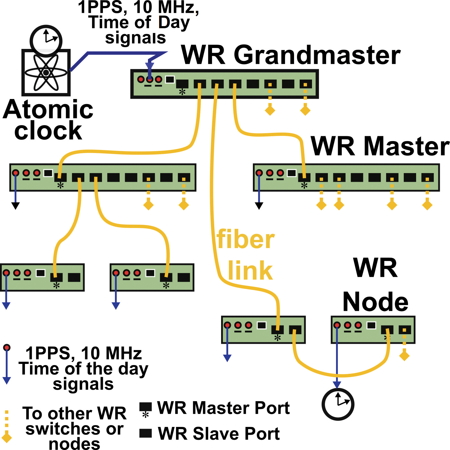
Initially developed for the Large Hadron Collider at the European Organization for Nuclear Research (CERN), White Rabbit (WR) is an accurate and scalable fiber-optic time and frequency transfer method that allows for dissemination of time references at sub-nanosecond level over distances of hundreds of kilometers. A typical WR network layout is shown in FIGURE 1.
FIGURE 1. Simplified topology of a White Rabbit (WR) network for optical time and frequency distribution. The yellow lines represent fiber-optic connections and the blue lines are electrical connections.
A central atomic clock provides synchronization references to a principal WR master switch dubbed the “grandmaster.” The grandmaster feeds synchronization signals into the network. which is expanded via fiber-connected WR devices: the switches and nodes of the network. These devices are serially linked to each other following a hierarchical master-slave pair configuration.
Accurate synchronization between a master and a slave WR-pair is performed as follows. The pair, which is connected via a bidirectional 1.25 gigabits per second optical Ethernet data link, quasi-continuously measures the round-trip delay of the data signals exchanged between the two devices. From these round-trip measurements, the one-way propagation delay, assumed symmetrical, is derived and compensated by the WR devices through an electronic control loop. To take into account possible asymmetries within a link, a calibration procedure is needed when initially installing the connection between a master and a slave. In practice, within smaller scale networks, the synchronization offset accuracy between devices is at the 100 picosecond-level. A 400-picosecond offset between WR devices has even been demonstrated over a distance of 169 kilometers, and more recently over a distance of 800 kilometers.
Besides the fiber-optic connection with other elements of the WR network, each switch or node can share its time-frequency references to an external device or system. These time-frequency references are available either in the form of IEEE 1588 Precision Time Protocol time stamps (via Ethernet connection), or in the form of electrical 1 pulse per second / 10 MHz synchronization signals (via coaxial cables).
THE CONCEPT
Centimeter- or even decimeter-level positioning accuracy is challenging to achieve using GNSS. In dense multipath environments, such as in urban canyons or indoor locations, the accuracy provided by GNSS is poor compared to the meter-level accuracy achievable in open terrain with the Standard Positioning Service. Moreover, GNSS services are vulnerable to interference, spoofing and jamming, and may be denied in indoor areas. We propose a TNPS based on a WR synchronization infrastructure as a complement to GNSS, providing higher timing and positioning accuracy, which also works in challenging environments.
TNPS can achieve decimeter-level accuracy in challenging environments through the use of wideband radio positioning signals. The attainable ranging precision is inversely proportional to the signal bandwidth. Furthermore, in dense multipath environments such as urban canyons, using wider bandwidth signals allows for finer time resolution. As a consequence, close-in received multipath components (MPCs) can be better resolved, and the LOS component can be more easily discriminated from delayed MPCs. This results in more accurate position solutions.
TNPS DEMONSTRATOR
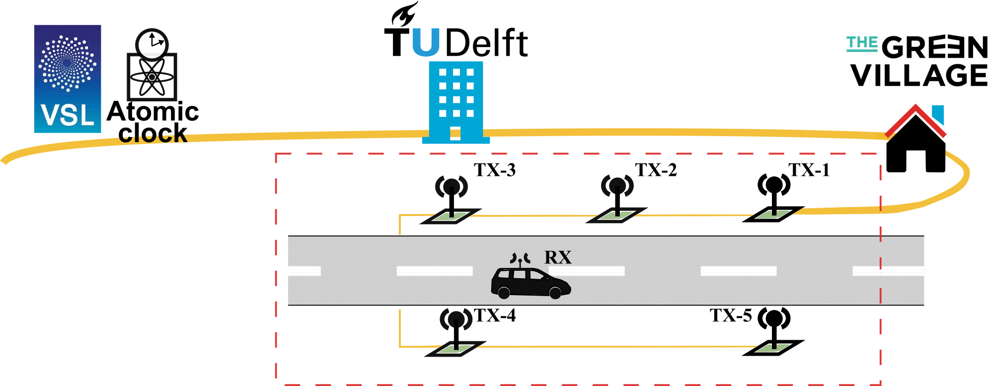
We performed a demonstration of the concept in Delft, The Netherlands, at The Green Village (TGV), an experimental facility on the campus of the Delft University of Technology. The facility aims to accelerate development and implementation of innovations for a sustainable future (see FIGURE 2).
FIGURE 2. Implementation of the TNPS demonstrator. The time-frequency reference is provided by VSL and forwarded to TU Delft via optical fiber (in yellow) and distributed through the optical WR synchronization infrastructure. Wireless radio transmitters (green squares) connected to the WR network deliver wideband ranging signals to perform terrestrial positioning and navigation.
The central synchronization reference of the TNPS demonstrator is the Dutch national timescale version of Coordinated Universal Time UTC(VSL), derived from atomic clocks at the Van Swinden Laboratory (VSL), the Dutch metrology institute. The UTC(VSL) 10 MHz frequency reference and 1 pulse per second time reference are fed to the WR grandmaster switch (WR-SW1). The grandmaster switch is subsequently connected to a distant WR switch (WR-SW2) through a 1,470-nanometer downstream and a 1,490-nanometer upstream 1.25 gigabit per second optical link. WR-SW2, located at one of the TU Delft data centers, synchronizes in turn a WR node (WR-N1) installed at TGV.
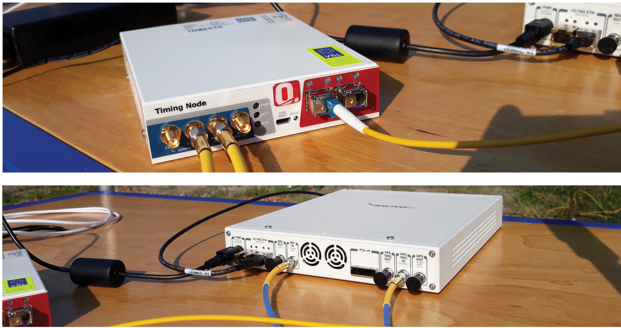
The remaining TNPS nodes at TGV are synchronized through a daisy-chain configuration. The first node (WR-N1) is connected to a second one (WR-N2), which is then connected to a third (WR-N3) and so on. In total, five timing nodes, WR-N1 to WR-N5, are connected to one another, using 50-meter optical fibers. These 5 timing nodes are used for synchronization (see FIGURE 3), and provide 1 pulse per second and 10 MHz electrical signals to five wideband radio transmitting units, uTX-1 to uTX-5, installed along a 50-meter stretch of road at TGV.
FIGURE 3. WR timing node (top) fed by a 1.25 gigabit per second bitstream through an optical fiber (yellow cable to the right) and providing electrical 1 pulse per second and 10 MHz synchronization signals at the outputs (two cables to the left). The bottom image shows an SDR system. The two channels of this device, capable of wideband operation, act here as a wireless transmitter or as a receiver. The transmitters are synchronized to the WR network through the 1 pulse per second and the 10 MHz electrical signals (blue-yellow cables at bottom) provided by the WR timing node.
A transmitting unit is based on a wideband transceiver: a software-defined radio (SDR) system linked to a wideband antenna that can operate from 700 MHz to 6 GHz. The antennas are connected to the SDRs using coaxial cables with a length of 5 meters and mounted on lampposts along the road at a height of about 4 meters. The transmitting units, uTX-1 to uTX-5, are respectively associated with antennas TX-1 to TX-5.
Each of these SDRs is capable of transmitting a wireless signal of up to 160 MHz bandwidth, on one or two of the device transmitter channels. The central frequency of each channel is tunable from 10 MHz to 6 GHz. In the demonstrator, we used a 3.96 GHz carrier frequency. The transmitting units periodically stream 160 MHz wideband quadrature phase-shift keying (QPSK) modulated pseudorandom noise (PRN) ranging signals sampled at 200 MHz. The five transmitters operate according to a time-division-multiplexing (TDM) scheme; uTX-1 to uTX-5 successively transmit the QPSK-modulated sequences as a 27.5-microsecond “burst” before turning idle. Between two successive transmissions, a guard interval of 3 microseconds is inserted during which all transmitting units are in idle state. It takes in total 150 microseconds for the five units to complete a transmission round, after which the units remain idle. The transmission round is then retriggered each millisecond.
At the receiver side (RX), another SDR platform is configured to acquire the QPSK modulated bursts transmitted by the five units uTX-1 to uTX-5. This SDR is actually playing the role of a data acquisition platform, which records and forwards the incoming sampled ranging sequences to the host PC via an Ethernet link. All processing and analysis in the demonstrator is performed offline, rather than in real time, using the collected ranging signals. The sampling rate of the acquisition platform is 200 MHz. A sample consists of a 16-bit in-phase value and a 16-bit quadrature-phase value (4 bytes in memory). In continuous operation, the SDR acquisition throughput would amount to 800 megabytes per second.
A throughput of 800 megabytes per second is difficult to handle for most of the host PCs. The SDR is therefore configured to only forward the relevant part of the data collected. Only the received samples time-aligned with the 150-microsecond transmitting window are periodically transferred to the host PC at a rate of 1 kHz. In practice, the acquisition window is slightly extended to 160 microseconds. Overall, the data throughput between the SDR and the host PC is now reduced to 128 megabytes per second; that is, 10 seconds of acquisition will generate a data file of 1.28 gigabytes.
A Schmidl & Cox synchronization sequence is embedded in the signal transmitted by uTX-1. The SDR field-programmable gate array continuously performs autocorrelation on the incoming samples and uses this sequence to detect the arrival time of the ranging bursts for operation in asynchronous mode. The receiver also can be operated in synchronous mode, that is, synchronized to a timing node.
TEST SETUP
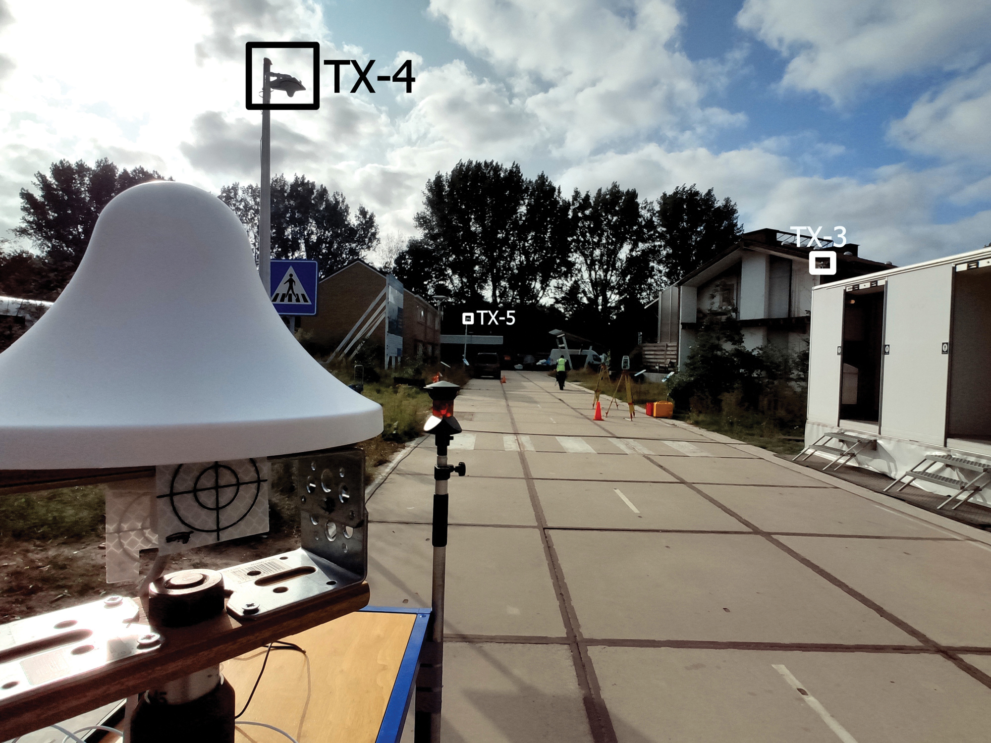
We carried out experiments on a 50-meter-long and 6-meter-wide local road at The Green Village (see FIGURE 4).
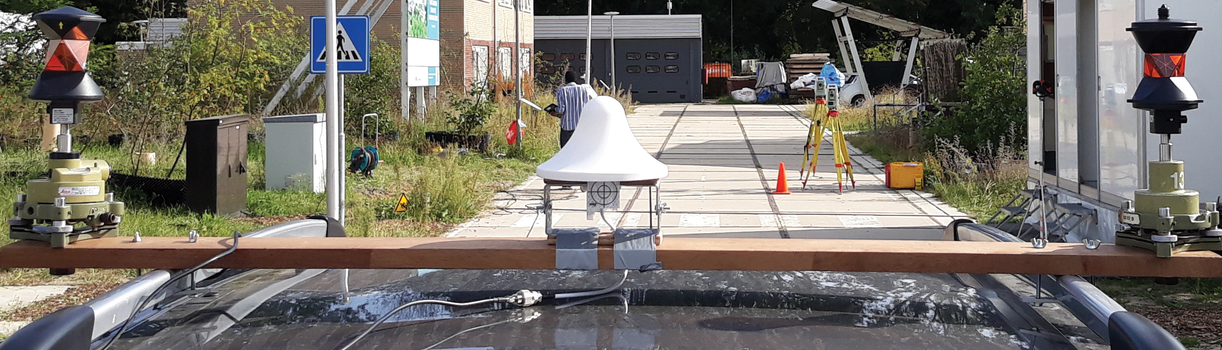
FIGURE 4. Test road at The Green Village, with three of the five roadside transmitting antennas (TX-3 to TX-5) as indicated. In the foreground, the receiver antenna is mounted on a trolley.
The road is bordered by built-up objects such as brick-wall houses, metal containers and large wooden advertising panels. These generate MPCs, which degrade the radio-positioning performance. The antennas TX-3, TX-4 and TX-5 can be seen mounted on lampposts. In Figure 4, the antennas TX-1 and TX-2 are on the right-hand sidewalk but not visible. The receiving antenna is in front to the left, mounted on a trolley. The RX antenna is identical to the ones used by the transmitters.
The receiver is used to perform a static survey at 50 locations on the road (staying at each point for around 1 minute). As shown in FIGURE 5, the receiver was also used for a kinematic experiment. The RX antenna is mounted on the roof of a car using a wooden beam. The RX antenna is linked via a 3-meter coaxial cable to the receiving SDR placed inside the car and connected to a host PC.
FIGURE 5. Receiver antenna mounted on the roof of a car. Two 360° prisms are used to determine the receiver ground-truth positions at the millimeter level, by means of land surveying total stations (placed on the yellow tripods in the distance).
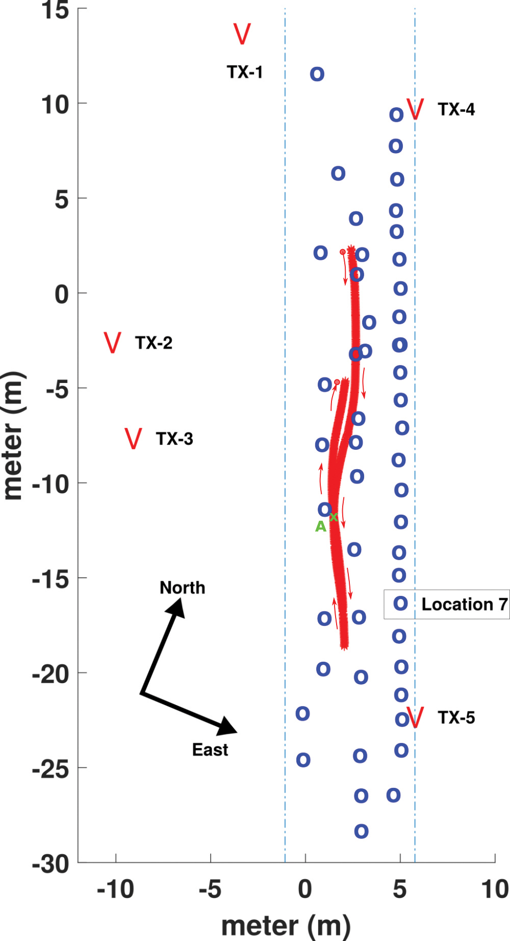
FIGURE 6 presents a map of the road with the static locations (in blue) and the forth-and-back kinematic track (in red). The transmitting antenna positions are indicated at both sides of the road.
FIGURE 6. Setup of the experiment on the local road at TGV. The locations of the transmit antennas, TX-1 to TX-5, are shown. Locations of static surveyed points are in blue, and the track of the kinematic experiment in red, with the RX antenna mounted on the roof of a car.
To establish a local coordinate system, the ground-truth positions of the RX antenna are determined using two land surveying total stations that rely on retro-reflective targets and 360° prisms to measure distances and angles. In Figure 4, a retro-reflective target, placed directly under the RX antenna, is visible, while the two total stations can be seen halfway down the road on the righthand side. In Figure 5, 360° prisms can be seen on both ends of the wooden beam on the roof of the car. The received signals are used to compute position solutions in post-processing, which are compared to the ground-truth values to assess the positioning accuracy. The accuracy of the ground-truth measurements is at the millimeter-level.
EXPERIMENTAL RESULTS
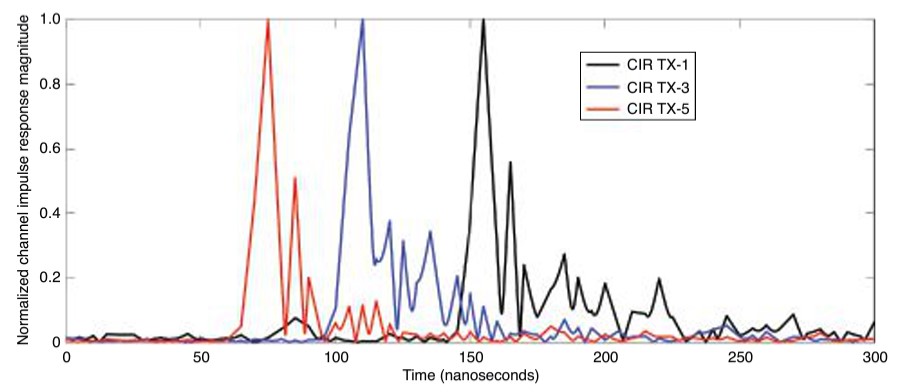
Achieving high positioning accuracy in a built-up area is difficult due to the presence of close-in MPCs, which arrive with very short time delays following the LOS component. FIGURE 7 shows the observed channel impulse responses (CIRs) between TX-1, TX-3, TX-5 and the receiver antenna RX placed at location 7 (see Figure 6). The LOS components can be easily detected as they correspond to the first and highest peak of each curve. However, we can also observe substantial close-in multipath components, which trail the main peaks. CIRs are obtained by division, in the frequency domain of the fast Fourier transform (FFT) of the received ranging sequences using the FFT of the known transmitted sequence. Oversampling by a factor of 100 is applied, as well as removing time delays of the TDM-scheme, such that the observed time delay difference directly represents the differences in ranges.
FIGURE 7. Normalized magnitude of the CIRs observed between the transmit antennas TX-1, TX-3 and TX-5 and the receiver antenna RX, positioned at reference point 7.
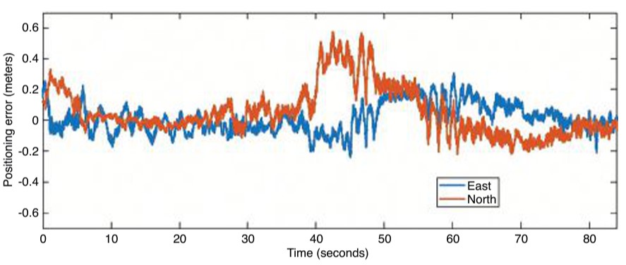
FIGURE 8. Time series of the positioning error in the east and north directions during the kinematic experiment.
Since the TNPS signal bandwidth is 160 MHz, the time resolution is about 6.25 nanoseconds, which corresponds to about 1.9 meters of propagation distance. A multipath component, which arrives at the RX antenna with a lag larger than 6.25 nanoseconds with respect to the LOS component, is likely to be resolved and will not affect (bias) the ranging result. In this case, using time-of-flight techniques, ranges between TX and RX antennas can be determined, often at decimeter level, by extracting the time-of-arrival of the LOS components. Comparatively, if a 20 megasamples per second rate is used (corresponding to a 20 MHz bandwidth, commonly used in GNSS), the time resolution is 50 nanoseconds. An LOS component and a multipath component arriving at the RX antenna can likely be discriminated if the receiver and the reflector are separated by at least 15 meters. If the arrival time between the two components is less than 50 nanoseconds, then the MPC cannot be resolved and will cause a bias when determining the propagation distance between the TX and RX antenna.
The first and largest peak of each CIR seen in FIGURE 7 represents the LOS component. MPCs can be seen trailing the LOS, typically within the next 50 nanoseconds. The MPCs cause a bias in the estimated range when they cannot be resolved. Using wideband ranging signals allows for better time resolution, and better discrimination between the LOS component and the MPCs.
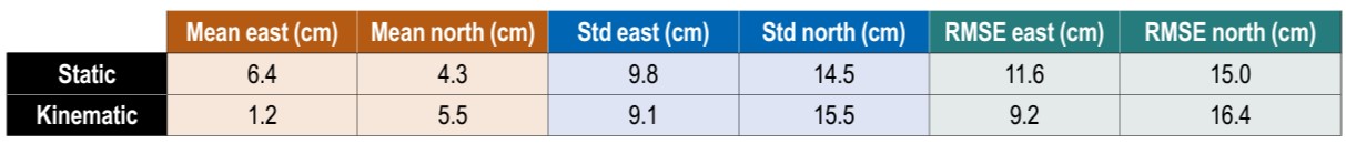
In the following, we assess the 2D positioning accuracy obtained using the demonstrator. 3D positioning is also possible with the demonstrator; however, since the TX antennas all are installed at similar heights and at a fairly low elevation compared to the RX antenna, we restrict our analysis to 2D positioning for the reason of having a poor geometry for determining the vertical position component. The 2D positioning model uses time difference of arrival (TDOA) pseudoranges allowing the cancellation of the asynchronous receiver clock offset. The frequency offset between the transmitters and the receiver has been estimated to be about 1 kHz, in asynchronous mode. After the TDOA ranges are computed from the experimental data, the 2D positioning problem is solved through Gauss-Newton iteration. Statistics of the static and kinematic 2D experiments are presented in TABLE 1.
TABLE 1. Static and kinematic positioning performance in terms of mean, standard deviation (std) and RMSE of position error, in east and north directions.
In the table, we present the mean position errors, standard deviations and root-mean-square errors (RMSEs) over the 50 surveyed points for the east and north directions. Mean errors of 6.4 and 4.3 centimeters are obtained for east and north directions, respectively. There is no significant bias in the system. In terms of RMSE, we can see that the positioning accuracy is just above 10 centimeters (11.6 and 15 centimeters respectively for the east and north directions). Overall, even with the presence of MPCs, and thanks to the synchronization accuracy and the wideband radio signals, a decimeter-level accuracy is achieved in static positioning.
The duration of the kinematic experiment was 84 seconds. Looking at the statistics of the kinematic experiment, the results for the east and north directions show a small bias and RMSE values of 9.2 and 16.4 centimeters respectively. The positioning performance in static and kinematic mode is close, both for the east and north components. In both cases, positioning performance is better in the east direction than in the north direction. This may be explained by better spatial diversity of the antennas towards the east direction. The time series of the position errors for the kinematic experiment is presented in FIGURE 8. Overall, the track error in the eastern direction is within ±2 decimeters (at a 95% confidence level). For the northern direction, a larger deviation is observed in the observation time span from 40 to 50 seconds (forward track), where the error in the north direction is close to 4 decimeters. Such a deviation is likely due to close-in MPCs resulting in a degradation of the accuracy for that part of the track. As a consequence, 82% of the position error in this track lies within ±2 decimeters. Outside this time span, the performance in east and north directions is similar.
CONCLUSIONS
This article presents the concept and results of a demonstration of a TNPS that uses WR to synchronize the transmissions of wideband radio ranging signals to achieve decimeter-level position accuracy in multipath environments, such as in built-up areas. A proof of concept of the TNPS was implemented at TU Delft. The developed prototype system demonstrates a decimeter-level 2D positioning accuracy in an urban road-like configuration bordered by built-up surroundings that cause substantial multipath.
ACKNOWLEDGMENTS
The research described in this article is supported by the Dutch Research Council, Nederlandse Organisatie voor Wetenschappelijk Onderzoek. We thank Lolke Boonstra and Terence Theijn from TU-Delft ICT-FM, as well as Rob Smets of SURF, the collaborative organization for ICT for Dutch education and research for their support and expertise on the optical infrastructure, and Loek Colussi and Frank van Osselen of Agentschap Telecom and René Tamboer and Tim Jonathan of The Green Village for their support in realizing the SuperGPS demonstrator. We also thank project partners Koninklijke PTT Nederland (KPN), Optical Positioning Navigation and Timing (OPNT) and Fugro.
MANUFACTURERS
The WR timing nodes V1.15 are by OPNT. The SDR systems for the transmitters and receiver are National Instruments (Ettus) X310 Universal Software Radio Peripherals. The 3-dBi wide-band antennas CM.02.03 are from Taoglas.
CHERIF DIOUF was a postdoctoral researcher in the Department of Geoscience and Remote Sensing at Delft University of Technology (TU Delft).
HAN DUN was a Ph.D. student in the Department of Geoscience and Remote Sensing at TU Delft.
GERARD JANSSEN is an associate professor in the Circuits and Systems Group of the Microelectronics Department at TU Delft.
ERIK DIERIKX is the principal scientist at Electricity & Time at the national metrology institute VSL in Delft.
JEROEN KOELEMEIJ is an assistant professor in the Department of Physics and Astronomy at the Vrije Universiteit Amsterdam.
CHRISTIAN TIBERIUS is an associate professor in the Department of Geoscience and Remote Sensing at TU Delft.
Seven Solutions sets new record for long-distance White Rabbit high-accuracy time-over-fiber link
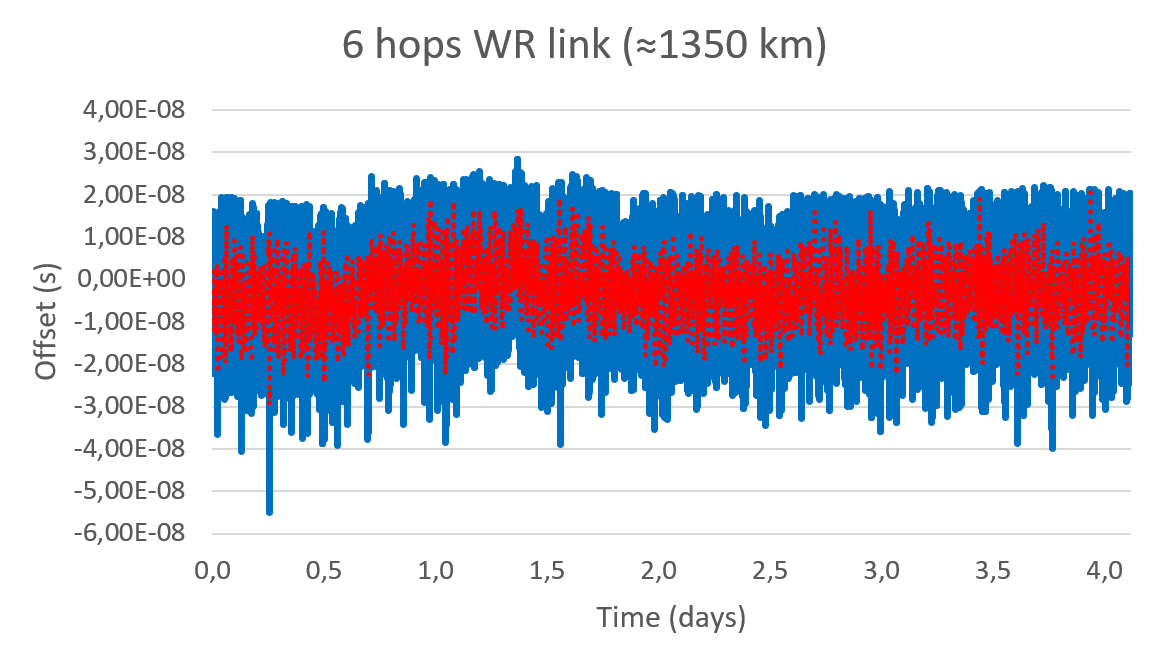
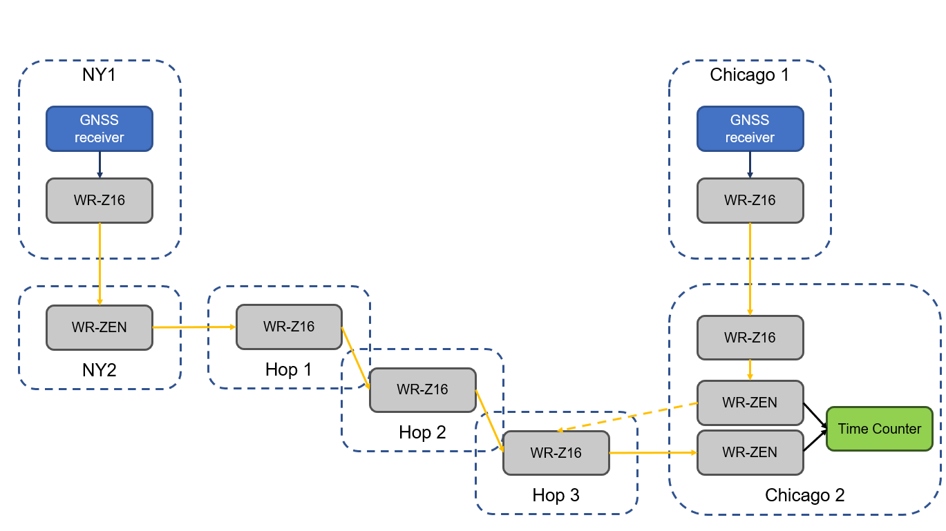
The White Rabbit link has an approximate distance of 1,350 km (840 miles) and was deployed in collaboration with Optiver U.S., a financial company, to connect Chicago and New Jersey trading locations. This link is formed by six long-distance White Rabbit hops using WR-Z16 and WR-ZEN TP devices connected by a combination of DWDM and SyncE-compliant transponders over a public telecommunication fiber network.
Seven Solutions is the leading company in the development and integration of high accuracy sub-nanosecond time transfer and frequency distribution for reliable industrial and scientific applications. Their technology integrates the White Rabbit protocol, the basis for the new high accuracy profile in the IEEE 1588-2019 (PTPv2.1).
This technology has become a reference for different sectors thanks to its unprecedented level of accuracy that outperforms current GNSS-based timing solutions, offering a suitable backup solution to deploy time dissemination networks. In the last few years, the White Rabbit technology has been adopted in the finance sector to deploy plug-and-play local area synchronization and metro-area links connecting different datacenters in financial hubs.
Although the performance of White Rabbit long distance links has been previously validated, this deployment sets a new distance record while integrating new resiliency and interoperability features using the latest WR-Z16 and the WR-ZEN TP devices.
Image: Seven Solutions
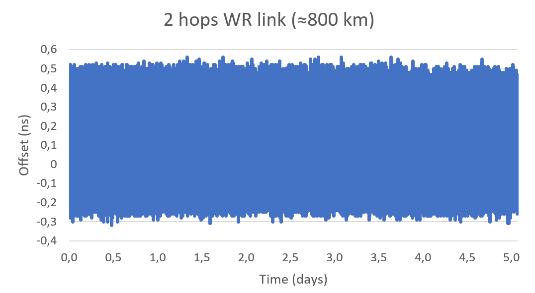
In a series of experiments, the link accuracy and precision were firstly validated setting a three long-distance hops loopback covering an approximate distance of 800 km (500 miles). In this case, the link was measured using an Agilent 53210A time interval counter for a five-day period. This experiment was intended to validate the feasibility of deploying White Rabbit links using commercial SyncE-compliant transponders and commercial telecommunication networks based on DWDM technologies.
Image: Seven Solutions
This measurement confirms the sub-nanosecond precision on a loopback and made it possible to perform network effect calibration to minimize the residual offset caused by the link asymmetry. In this case, a mean offset of 112 ps, a standard deviation equal to 139 ps and a peak-to-peak difference of 880 ps were obtained. Additionally, the offsets followed a gaussian distribution with no daily trends impacted by temperature or humidity.
This result proves the ability of high-accuracy time-over-fiber dissemination to fulfill the most demanding telecom requirements (class D Telecom Boundary Clocks) and corroborates one of the conclusions from the Analyzing a More Resilient National Positioning, Navigation, and Timing Capability report released by the RAND Corporation earlier this year:
“White Rabbit can support time transfer with accuracy that substantially exceeds the needs of almost all users; it is better than GPS. Therefore, this method is a strong candidate for backing up GPS time transfer for users that require atomic clock accuracy and for serving as a ‘national backbone’ for time so that secondary users, such as cellular networks, can perform to the limits of its own subdomain without suffering additional inaccuracies of its own master clock. Less accurate methods, like ordinary PTP, could provide timing to the vast number of other users, like mobile and cellular users.”
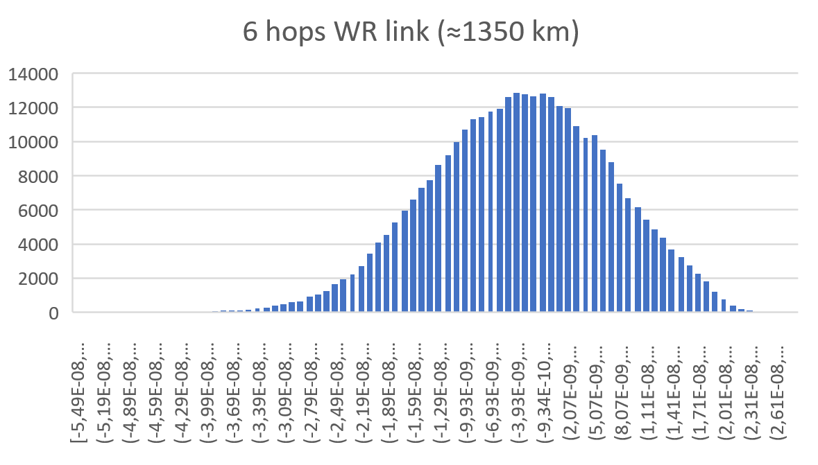
In a second test, the whole link was deployed using GNSS receivers in both ends of the link. The first GNSS receiver was used as the time reference in one end of the link (located in New Jersey) and the second GNSS receiver was used in the second end of the link to compare to the time reference (located in Chicago). Both GNSS receivers are the same model and have a 15 ns RMS jitter specification. In the second location, the local GNSS reference was compared to the remote time reference originating from New Jersey through the long-distance White Rabbit link.
Image: Seven Solutions
This resulted in a mean offset equal to 2.98 ns, a standard deviation equal to 10.4 ns and a peak-to-peak equal to 83.3 ns. It is noteworthy that due to the time interval counter, some of the samples were filtered. This effect is shown on the histogram but is considered negligible to validate the feasibility of the link.
Image: Seven Solutions
Additionally, the White Rabbit protocol automatically corrects daily effects due to temperature or humidity changes in the link, which are not observed in the measurement even when the GNSS receivers are located more than 1,000 km away from each other. This does not represent the real White Rabbit link error but indicates the limitation of using GNSS receiver to accurately measure the link accuracy.
As can be estimated from the measurements, the previous test and the GNSS specifications, the White Rabbit link maintains an approximately ±1 ns precision. In fact, the results show that the GNSS receivers are outperforming their specifications by almost 50%. The final accuracy is influenced by the GNSS receiver calibration. This link can be calibrated using network effect techniques (as shown in the previous experiment) or using the GNSS receivers themselves.
This experiment complements the results obtained in the U.S. Department of Transportation GPS backup demonstration showing the White Rabbit technology (which was catalogued as the most accurate alternative technology for time distribution) in a real telecommunications network scenario with very long distances. Additionally, it justifies the industrial need to deploy high accuracy time distribution when providing an alternative to GNSS-based timing, as it provides a next generation technology that can benefit other PNT systems and several critical infrastructures that rely on time synchronization for daily operations.
Beyond this, White Rabbit is demonstrated as a disruptive technology that can be used to measure the performance of GNSS in various locations to develop a warning and backup system, to connect high stability time references (for example, atomic clocks) for a suitable long-term ground-based backup to GNSS systems or to connect national metrology institutes around the world to compare different time scales.
This long-distance link represents a new milestone in ultra-accurate time transfer over existing telecom networks that allows cross-validating different linked references or accurately synchronizing them for coordinated actions at tight relative timing.
Furthermore, the deployment through existing telecom network proves its feasibility at affordable cost and opens the door to new disruptive applications. Atomic clocks have evolved to represent very stable references, but it has been typically assumed that time degrades as it is transferred over long distances making accurate comparisons between different references a challenge. This new generation of long-distance links represent a step further into tightly synchronizing different devices over fiber at long distances making them resilient to the vulnerabilities of GNSS timing.
This level of accuracy is key for certain applications and sectors nowadays. Matt Nassr, Data Engineering Lead at Optiver, remarked “Partnering with Seven Solutions has allowed us to better optimize for the highly distributed nature of the financial markets. Being able to establish a nanosecond-level precision link across the Chicago-New Jersey path further improves our ability to provide liquidity across the major US exchanges.”
“This is not a first step on the deployment of long-distance time synchronization networks, this is just one step further,” said Francisco Girela, Americas tech responsible at Seven Solutions. “We have been working for years on improving our devices, easing the monitoring and management, enhancing the resiliency, integrating failover features, adding interoperability with IEEE 1588 (PTP), NTP or PPS and allowing the integration of High Accuracy timing in third party devices thanks to the HATI core. During this journey we have learnt how to integrate the technology to work at its best and we have proved its effectiveness in telecom, data centers, finance, defense, or power grids among others.”
When asked about next steps, Francisco added, “We want to demystify this technology. People think that its deployment is complex or overkill, but that is not true. We see White Rabbit as the core technology to build alternative PNT systems, setting a sub-nanosecond timing foundation that will push the development of a more diverse and more accurate technology ecosystem.
“We have worked to evolve White Rabbit devices to be a market commodity when deploying time synchronization in local areas but providing a level of accuracy that will fulfill the requirements for the current applications and for the next decade. For long distances, complex deployments, or projects we are always happy to assist our customers and partners to get the best from our devices. We are sub-nanosecond natives; we care for every single picosecond.”