The FAA’s announcement (reported in March GPS World) that WAAS in the northeastern United States and eastern Canada may be significantly inhibited by relocation of WAAS-broadcasting satellite AOR-W before the new PanAmSat becomes fully operational in fall 2006 caused unease in some surveying organizations. Based on tests completed last year, before anyone knew that AOR-W would relocate to 142W longitude, these organizations replaced legacy GPS mapping units using post-processing and the Coast Guard NDGPS with high-performance WAAS-enabled mapping receivers.
The FAA notice doesn’t tell the full story, however. Two new WAAS broadcasting satellites launched last fall. PanAmSat (133W) began broadcasting in test mode with corrections full-time this March, and Telesat (107W) is scheduled to begin the same mode on or around April 1, 2006. The FAA announcement does not take into account either of these broadcasting satellites.
If these test signals are considered, there will be no degradation in WAAS visibility. In fact, users in the northeastern United States and eastern Canada will enjoy dual WAAS satellite coverage. WAAS satellite visibility in central and western North America has improved in the past 60 days with the new test signals and relocation of AOR-W.
However, the FAA won’t certify the accuracy/reliability of the new satellites until after extensive testing. Until then, non-aviation receivers may use the signals at their discretion —the same mode WAAS operated in prior to its July 2003 commissioning. Also, non-aviation WAAS receivers may not be configured to use the new test signals; check with the manufacturer.
— Eric Gakstatter, Editor of GPS World’s new Survey & Construction E-Newsletter
Hello, and welcome to the first issue of GPS World’s Survey & Construction Newsletter. You are encouraged to forward this email to your colleagues, and they in turn are encouraged to sign up for their own — free — subscription.
I’m Eric Gakstatter ([email protected]), your editor on this resource for the survey and construction communities. I’ve spent the past 16 years in the GPS survey/mapping industry using many brands of GPS equipment and software. My first ten years in GPS were spent as a product manager and the last six years as a GPS user and consultant. I’m a non-partisan advocate for the GPS user community.
The first subject I’ve selected to discuss with you is the FAA’s WAAS program because of the recent and significant changes that have taken place in this program.
WAAS UP?
WAAS is one of the most widely misunderstood GPS technologies of today in the survey/mapping marketplace. Recent WAAS broadcasting satellite launches and a WAAS broadcasting satellite relocation along with vague press releases have further muddied the waters. In the interest of panic-relief for survey/mapping WAAS users, a more prudent, in-depth explanation is warranted.
Recently, I was on a construction site for a project I’m involved with. It was a park-like setting with a lot of drainage and irrigation being laid. From the beginning, I knew the job superintendent was very comfortable with technology. The younger, lean fellow spoke efficiently, carried a laptop and seemed on top of his game when questioned by various owner’s reps and sub-contractors….he even carried a hand-held GPS mapping receiver that he used to map various structures installed throughout the project.
Of course, I had to talk with him about his thoughts and perceptions of GPS. A part of the conversation went as follows:
Me: How accurate has that unit been for you?
Him: Very accurate. Do you see that little airplane on the screen (he points at the screen)?
Me (looking at his screen and trying to figure out what he’s talking about): Oh, yes.
Him: That means there’s an AWACS airplane flying near here sending me corrections. You know, the military airplane with the big antenna on it?
I sighed deeply as the image my mind had built of this young, high-tech construction superintendent faded away.
That “little airplane” on the screen he was referring to was an indicator that his GPS receiver was using corrections from a Federal Aviation Administration (FAA) Wide Area Augmentation System (WAAS) satellite.
WAAS is perhaps one of the most widely misunderstood GPS technologies of today in the survey/mapping marketplace and the above conversation is a typical example.
Further complicating this is the recent announcement by the FAA that WAAS in the northeastern US and Eastern Canada may be significantly affected by the relocation of AOR-W (the US east coast WAAS broadcasting satellite) before the new PanAmSat will be considered fully operational in Fall 2006. See the FAA announcement at http://gps.faa.gov/programs/waas/non-aviationUsers.htm.
The FAA announcement set off a panic in some organizations that had recently implemented a significant number of high performance, WAAS-enabled mapping receivers to replace legacy GPS mapping units that used post-processing and the Coast Guard NDGPS system. These organizations based their decisions on performance tests completed last year before anyone knew that AOR-W was going to relocate to 142W longitude instead of 98W longitude as originally announced.
The rest of the story…
First of all, two new WAAS broadcasting satellites were launched last Fall. One of them (PanAmSat at 133W longitude) began broadcasting in test mode with corrections full-time this month (March). It is expected that the other (Telesat at 107W longitude) is scheduled to begin broadcasting test mode with corrections full-time on or around April 1, 2006. The FAA announcement does not take into account either of these broadcasting satellites.
If these test signals are considered, there will be no degradation in WAAS visibility. In fact, users in the Northeastern US and Eastern Canada will enjoy dual WAAS satellite coverage. For example, in Montreal, Quebec the two new WAAS broadcasting satellites will be visible at ~28 degrees and ~12 degrees above the horizon. Before the AOR-W relocation, it was the only WAAS satellite visible and it was at ~36 degrees above the horizon.
WAAS satellite visibility in the central and western US, Mexico and western Canada has improved dramatically in the past 60 days with the new test signals and relocation of AOR-W. For example, in Portland, Oregon, WAAS satellite POR is visible at ~12 degrees above the horizon. The two new WAAS broadcasting satellites and relocation of AOR-W to 142 degrees west longitude now means that three additional WAAS satellites will be visible at ~32 degrees, ~36 degrees, and ~35 degrees above the horizon in the Pacific Northwest.
The caveat is that the FAA won’t certify the accuracy/reliability of the new WAAS broadcasting satellites for quite some time after extensive testing. Until that time, non-aviation receivers are free to use the test mode signals at their discretion. This is the same mode that WAAS was operating in prior to it’s July 2003 commissioning. Also, your non-aviation WAAS receiver may or may not be configured to use the new test signals. You should check with the manufacturer of your unit.
Well, I didn’t have the heart to tell him then there weren’t any AWACS airplanes sending him corrections (although I did tell him later). It’s just one more example I’ve encountered of the misinformation floating around about WAAS among survey/mapping professionals. There is not enough space in this issue to debate the advantages/disadvantages of WAAS for survey/mapping usage, but don’t be so quick to dismiss the technology before you fully investigate it’s performance and consider the recent developments.
By James R. Clynch, Andrrew A. Parker, Richard W. Adler, and Wilbur R. Vincent, Naval Postgraduate School; Paul McGill and George Badger, Monterey Bay Aquarium Research Institute
“Mr. Holmes, they were the footprints of a giant hound!”
Engineers-turned-sleuths in Moss Landing Harbor, California, had a similar clue to go on: the tracks of a GPS jammer across a spectrum analyzer. For months, the elusive culprit had jammed GPS signals in the harbor. The team of engineers roamed the waterfront with a spectrum analyzer and receiver. They identified and apprehended not one, but two distinct suspects, and unearthed evidence of the existence of a third — all readily available, commercial-grade television antennas.
After interrogation in the laboratory, tahe guilty devices were turned over to the authorities for appropriate action.
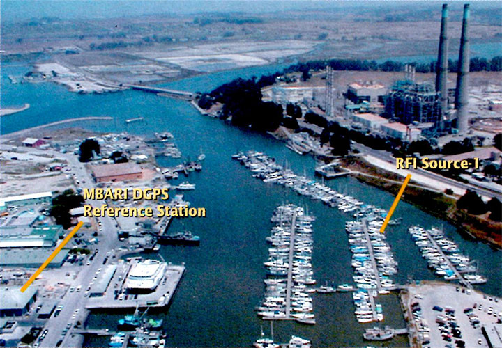
A view from the location of an unintentional GPS jammer across Moss Landing Harbor to the Monterey Bay Aquarium Research Institute. A GPS receiver with its antenna on the other side of the roof was continuously jammed for months.
In April 2001, the captain of the research vessel PT SUR, based in Moss Landing, California, made a radio telephone call from at-sea to one of the authors, stating that signal reception of GPS in the whole of Moss Landing Harbor was jammed. He was advised to contact the U.S. Coast Guard (USCG) and the Federal Communication Commission (FCC). When the problem persisted for another month, we launched an effort at the local level to determine the cause of the jamming.
Moss Landing is a moderate-sized harbor about 100 kilometers south of San Francisco, in the middle of Monterey Bay. It has a mixed fleet of working fishing boats, pleasure craft, and three large research vessels used by the local scientific community.
The Naval Postgraduate School (NPS), with a large program in science and engineering, is located at the south end of Monterey Bay. The Monterey Bay Aquarium Research Institute (MBARI) has its headquarters in Moss Landing and two major research vessels berthed there. This organization supports the Monterey Bay Aquarium and also has a large engineering program, especially in underwater remotely operated vehicles.
Locations of the RFI emitter and MBARI; power plant upper right.
MBARI has used GPS for precision location of their vessels since the early 1990’s, before the U.S. Coast Guard set up their system of DGPS stations along the coast. MBARI, with assistance from NPS, set up a differential station at their location at Moss Landing, using a UHF data link to send the corrections to their vessels.
After the April jamming report, NPS set up a monitor of the MBARI DGPS corrections to log the number of satellites being tracked. This clearly showed that the station was being heavily jammed. Reports of other GPS users in Moss Landing confirmed that it was a jamming issue and not a faulty receiver.
The jamming had impacted MBARI in several ways, including causing it to loose its GPS-based high-accuracy time reference. It would have caused difficulty at the narrow harbor entrance in fog. In at least two cases it caused small-boat owners to buy new GPS receivers, only to find they still could not get GPS in and around Moss Landing. One of the major ships in the harbor paid for a technician and new equipment to fix the problem, but finally had to turn off GPS in the harbor area, give the alarm that GPS was off line, and use radar only for harbor entrances in bad weather.
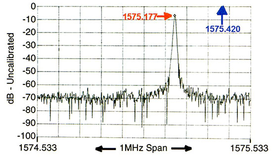
The GPS signal that feeds the MBARI reference station was also distributed to several laboratories and offices in the MBARI headquarters building, through a series of splitters and inline amplifiers. In an office with one of these drops, we set up a high-quality spectrum analyzer to examine the energy in a wide band about the GPS L1 frequency. Because there were several long cables and amplifiers between the antenna and the spectrum analyzer, the signals were not calibrated at the time they were taken. Later the system was calibrated. Figure 1 shows an example of the data recorded with a clear peak from the radio frequency interference (RFI) source many dB above the level of the GPS signals.
Figure 1. spectrum of Source-1 on a spectrum analyzer, VBW 3 KHz, RBW 3 KHz.
Identifying Source-1
We began our search for the source of the jamming radiation in early May, 2001, spending several days looking for it. Two factors complicated the effort: the large number of metal objects that reflected the energy, and the shifting of the frequency of the emitter.
George Badger fabricated a 17-element antenna with about a 30-degree beamwidth and used this with a portable communications receiver, a general purpose radio that fit in a shirt pocket. The initial search drove along the roads in the area and stopped at widely spaced locations to record the peaks of the RFI signal. We found multiple peaks in all locations, coming from the many reflecting structures in the area, including the largest conventional power plant in California.
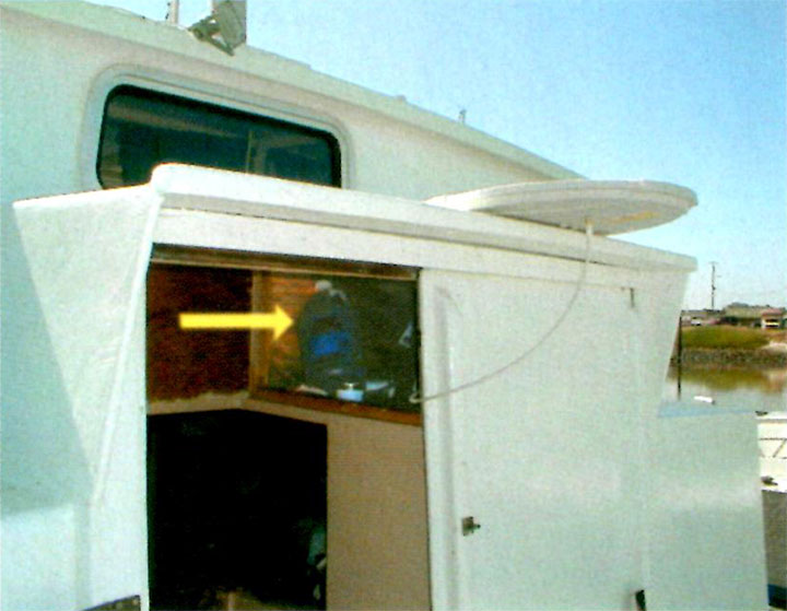
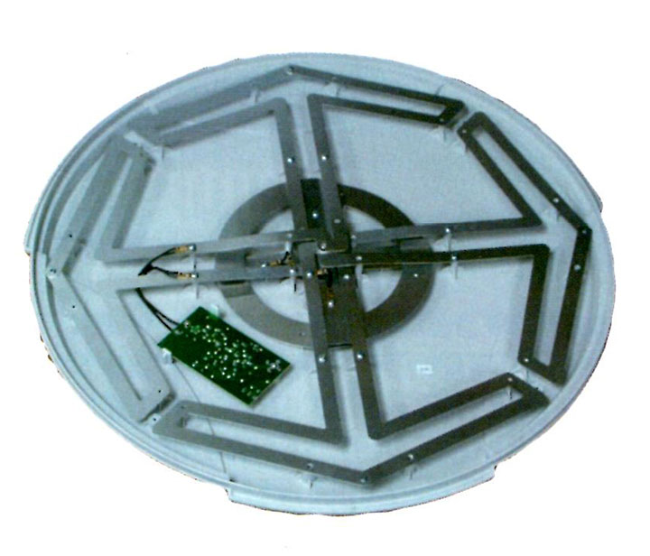
From its normal location inside the paint locker (see arrow), the antenna jammed all of Moss Landing Harbor and an area at least 1 kilometer out to sea.
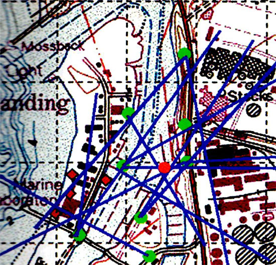
Figure 2 shows the locations where bearings were taken as green circles, and the bearings in blue. The red circle shows the actual location of the emitter. Without the red dot, it is hard to define where the most likely position is. After ruling out the power plant, we decided to look where there were no building or other reflectors.
Figure 2. Search for bearing for Source-1.
Closing In. The team put the spectrum analyzer on a cart along with the small radio, and took them to the dock area. Even then it was confusing. Only by turning off shore power to individual boats could we determine the actual emitter location. The signal stopped and started again as we turned power to the vessel emitting the RFI signal off and on. The photograph, taken by a “kite camera” at about 200 meters, shows the locations of the RFI emitter, MBARI, and the power plant.
Source-1 with cover open, showing the small preamplifier that jammed GPS.
We contacted the boat owner and gained access, quickly determining that the emitter was a commercially available VHF/UHF television antenna with built-in preamplifier. The antenna was powered by an AC/DC adapter plugged into boat AC power. The preamplifier was thus powered all the time, even when the TV was not on. In fact, the TV was seldom on, and most of the time the TV antenna was in a paint locker inside the locked boat. From this interior location, its emissions jammed all of Moss Landing Harbor and an area at least 1 kilometer out to sea.
The day after we located the jamming antenna, we purchased it from the owner, took it to NPS for study, and informed the Federal Communications (FCC) San Francisco field office. We also distributed a memorandum describing the facts of the case to the U.S. Coast Guard and the GPS Joint Program Office (JPO).
Characteristics of Source-1
At the Naval Postgraduate School, we studied the antenna under controlled conditions and found it to have an internal preamplifier that exhibited unintended oscillations. The unit was normally powered from an inexpensive 12-volt AC/DC converter. In the tests it was powered from both this unit and a battery.
We studied the characteristics of the emission using another spectrum analyzer with its output sent to a waterfall display.
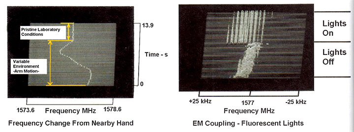
The unit proved extremely sensitive to the physical and electrical environment. We knew this from our search procedure, when modulation on the signal was recognized by its distinctive sound as a boat bilge pump. In an ad hoc experiment, we noted that the frequency varied over 3 MHz when one of us slowly moved his hand about 20 centimeters when it was 3 meters from the antenna. This is shown on the left in Figure 3. When the hand was held still, the frequency was much more stable, as seen by the section at the top of the traces.
Figure 3. Frequency changes in Source-1 caused by environmental factors.
In another case, when running on batteries, the spectral pattern changed considerably when the overhead fluorescent lights were turned on and off. This effect is shown on the right. In order to get the narrow lines in the “lights on” condition, the spectrum analyzer was synchronized to the AC line frequency. We also found that the operation of a low-powered, hand-held transceiver (100 mW) operation at 150 MHz and 450 MHz caused large shifts in the oscillation center frequency.
To better investigate the electromagnetic coupling, we placed the unit in a good screen room. We were interested to see if you needed an external RF field from the lights, for example. It still oscillated, indicating that the oscillation would emit RFI energy just by being turned on. No special external conditions were required.
We obtained several other tests results, but conclude principally that the oscillation was self-exciting and very sensitive to environmental conditions.
The Suspects Multiply
During the hunt for RFI Source-1, NPS monitored the DGPS corrections broadcast by MBARI, automatically recording and plotting the total number of satellites for which corrections were generated every few days. While Source-1 was active, there were no satellites being tracked.
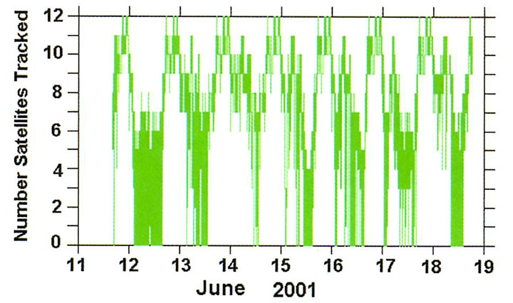
A few days after Source-1 was removed, we again plotted this log. Much to our surprise, there were still long periods when the MBARI GPS receiver was tracking few or no satellites. The MBARI GPS receiver was being jammed during most nights. Figure 4 shows a plot of the number of satellites tracked.
Jamming of MBARI GPS after Source-1 was removed from harbor.
We conjectured that the jamming’s diurnal pattern derived from the temperature sensitivity of the second jammer’s center frequency. This turned out to be correct. The jamming was correlated with temperature and ended most days before 11 am.
This told us that we would have to hunt the source location at night and early morning.
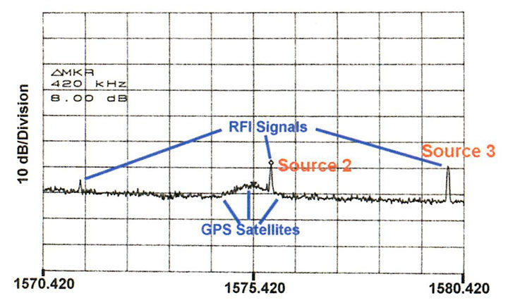
Field Operations. The San Francisco FCC field office sent a team several times to Moss Landing to hunt for Source-2, and on several days both MBARI and NPS assisted. The MBARI high-quality spectrum analyzer monitored the signal from the laboratory this time, showing that its frequency moved during the morning hours and its level decreased as the temperature rose. We sent this frequency via cell telephone to the mobile team in the harbor seeking the RFI source. Figure 5 shows a typical early morning spectrum taken after removal of Source-1. Again the hunt was not easy.
Figure 5 shows a typical early morning spectrum taken after removal of Source-1. Several signals are visible in this spectrum, in addition to a broad peak in the middle from the GPS satellites. This was not seen in the spectra taken earlier because Source-1 masked it. The peak in the GPS band comes from Source-2.
On the second FCC trip to Moss Landing Harbor, the signal in the GPS band had dropped by 10 dB in the late morning. We decided to hunt for the source of of a higher-level signal just outside the GPS band. This is the line at about 1580 MHz shown in Figure 5. The combined group quickly located the source of this signal. Again the combined use of a spectrum analyzer and portable receivers with a narrow-beam antenna was important. We also monitored the frequency on the spectrum analyzer inside MBARI and relayed the current value to the field team by cell telephone.
Authors Badger and McGill with a 13-element yagi antenna and communications receiver used in dockside search.
In the end, turning the power on and off to a few boats and correlating this with the RFI signal identified the culprit. It turned out to be a another commercially-available UHF/VHF television antenna on a boat, one dock over from Source-1. When it was turned off, only the line near 1580 MHz went away. Therefore we labeled this perpetrator as Source-3. This owner returned the unit to the place of purchase for a replacement.
The FCC has determined that the preamplifiers in Source-3 and Source-1 came from the same factory, which sold units to at least four well-known U.S. brand names of consumer electronic equipment. The bad units apparently began with a design change in late 2000; the number of units sold is not known to the authors.
Suspect Roundup. It is now clear that there were at least three signals capable of jamming GPS in the Moss Landing Harbor area. Two were located and removed by a coordinated effort of MBARI, NPS and the FCC.
The FCC made a few more attempts to locate Source-2 during the summer, but its level was lower with the higher temperatures. In the fall of 2001, the FCC succeeded in locating Source-2. It again turned out to be a VHF/UHF television antenna with preamplifier.
Calibration
There were a large number of spectra taken in the MBARI office. The signal came in the DGPS reference station antenna and went through two splitters and one inline amplifiers in the approximately 80 meters of low loss cable before emerging in the engineering office. Rather than examining the individual elements, we decided to calibrate the entire system.
A calibrated source was sent to a standard antenna about 2 meters from the antenna. The same analyzer used to acquire data on the RFI sources was configured as it had been for the experimental data. The antenna manufacturer supplied beam patterns for the antenna. In this way, the signals were now calibrated at the level outside of the antenna.
There still is an uncertainty about the space loss and antenna beam pattern gain/loss for actual sources. The latter can be found for the signals located, but not unknown signals such as Source-2. Accordingly the data were calibrated as a power level at the outside of the MBARI antenna.
Comparison to a RFI Specification
The composite Figure 6 shows one spectra, now calibrated to dBm outside the antenna, and a specification for the RFI levels. This is the specification that aircraft GPS receivers used for GPS landing systems must meet. The values measured from several other spectra taken at MBARI have also been plotted on this figure. Clearly these signals were above the narrow band limits by amounts from 3 to 24 dB.
Source-1 had the highest level at -96 dBm. Its location is known to have been 325 meters from the MBARI antenna. It was at an elevation angle of -2.5 degrees. While the beam pattern of Source-1 is unknown, if it were omni-directional, it would exceed this FAA specification at a range of 50 kilometers or more. It is known to have caused marine GPS receivers to lose lock out to 3 kilometers. The effective power of this source can only be bounded from the data available. It is at least a few milliwatts.
Source-2 varied in frequency and level. While on top of the L1 frequency, it had a level of -106 dBm. Source-3 had a level at MBARI of -99 dBm. While it was about 12 MHz from the center of L1, the variation in manufacture is likely to have produced units with emissions much nearer L1.
Conclusions
In one small California harbor, at least three emitters capable of jamming commercial GPS receivers were present. Two were located and removed by the authors. They were active UHF/VHF TV antennas and appeared to have the same internal preamplifier. The FCC has located and removed the third.
Locating these sources proved difficult. It required a spectrum analyzer with averaging capabilities on a broadband antenna to track the jammer frequency and a narrow-band portable receiver with a directional antenna to localize it. Even then, a power on/off test was needed to verify that the source had indeed been found.
The existence of the jamming was well-known in Moss Landing Harbor, and reported at least once to appropriate agencies. However, the problem persisted until local engineers and scientist hunted down the worst offender. Clearly there was a system problem with reporting and removal of RFI sources. More education of harbor masters or some other change needs to be implemented to deal more quickly with this type of problem.
Acknowledgement
Gary Thurmond, a retired MBARI engineer, provided technical advice and participated in the location of Source-1 and took the aerial photograph of Moss Landing Harbor.
James R. Clynch is a research professor at the Naval Postgraduate School in Monterey, California, and has worked for 30 years in the use of satellite navigation systems for precision positioning and to study propagation effects. He has a PhD from Brown University.
Andrew A. Parker, Richard W. Adler, and Wilbur R. Vincent are research professors in the Department of Electrical and Computer Engineering at the Naval Postgraduate School. Their PhDs are from University of Maryland, Pennsylvania State University, and Michigan State University, respectively.
Paul McGill is an electrical engineer and George Badger a microwave technician at the Monterey Bay Aquarium Research Institute.
Manufacturers
The MBARI differential station uses a Trimble RL 4000 GPS receiver. The waterfront search employed a Hewlett Packard 8562 spectrum analyzer and an An ICOM IC-R3 5 communications receiver. A Hewlett Packard 8562E spectrum analyzer was used at NPS to study the emissions. Trimble Navigation provided a beam pattern for the specific antenna used on the MBARI roof, and the antenna used for calibration.
By Jimmy LaMance, Javier DeSalas, and Jani Järvinen
Published: March 2002 GPS World
Have you ever tried to use a GPS receiver indoors? Chances are, unless you were on the top floor of a wood-frame house and using a receiver with ample antenna gain, you couldn’t get a position fix. GPS is a marvelous positioning tool but it does have some weaknesses, one of which is low signal power. And unlike cellular telephones, conventional GPS receivers do not work well, if at all, unless their antennas have a clear view of the sky. Although future GPS satellites will transmit signals with higher power, it will be a decade or more before the current constellation of satellites is fully replaced. In the meantime, how can GPS be used in skyscraper canyons, inside office buildings, and even in underground parking garages? Assisted GPS comes to the rescue! In this month’s column, a team of researchers from the United States and Finland describe their approach for assisted GPS — one which does not require a huge infra- structure investment for service providers.
The Global Positioning System has provided more than a few ironies in its relatively short existence: A system so accurate that, until last year, government policy required operators to degrade the quality of the open C/A-code signal. A navigation instrument more accurate than the maps across which navigators plotted their courses. Early GPS-based car guidance systems that displayed vehicle location in the middle of buildings or lakes.
But, as with so many other aspects of daily life, what may have seemed funny before September 11 is no longer a laughing matter..
The need for a better correspondence of location information is underscored by the urgency being given to the Federal Communications Commission’s (FCC’s) five-year-old mandate for enhanced 911 (E911) services. E911 provides mobile telephone users with the same automatic location information (ALI) of emergency calls now en-joyed by users of wireline phones at fixed sites. The benefits of ALI for getting police, firefighters, and ambulances to an emergency quickly are obvious..
The first phase of E911 implementation — identifying the nearest cell site from which a call comes — only covers less than half of the U.S. population. Implementation of Phase II, which requires much more accurate real-time positioning, was scheduled to begin October 1. Last month, however, the FCC granted extensions to five national wireless carriers for initiating their Phase II plans. The agency still expects carriers to provide all mobile phone users with E911 coverage by the end of 2005..
Three wireless carriers will employ handset-based assisted-GPS techniques in providing ALI that must be twice as accurate (50 meters versus 100 meters) as the “network-based” positioning that the other carriers have selected. (This should prove interesting in the marketplace. Because the E911 capability imposes no direct cost on customers, why would consumers choose non-GPS equipment and carriers offering substantially less accurate service?).
Little of the E911 delay stems from unavailability of GPS technology. Upgrading software at switching servers is the primary cause for postponements sought for handset-based systems. Even with the lower accuracy standards, however, carriers with network-based solutions pleaded for more time to get their positioning technology to work..
After the communications and positioning kinks are worked out of the E911 systems, public safety and commercial location-based service providers will still face an operational dilemma. That is the mismatch between positioning techniques and mapbases and differences among maps discussed earlier. Cartographers have long understood that variations among coordinate systems and datums can make the same latitude/longitude mean different things to different people. But until GPS came along, navigation and tracking techniques were so much cruder that such cartographic variations disappeared inside the error ellipse of the positioning systems..
Under Phase II, emergency call centers (public safety answering points or PSAPs, in FCC parlance), public safety agencies, and E911 callers need to be on the same page. Use of proprietary mapbases with incompatible grid designs in either paper or electronic format is a recipe for disaster. It will create coverage ambiguities near PSAP boundaries (Which agency should handle the call?) and lead rescuers tens or even hundreds of meters away from injured or imperiled callers. Yet a distinctive reference grid seems like a much less important proprietary feature for competing map vendors than the other information and cartographic design built into their products..
The Public X-Y Mapping Project has proposed one solution to this mishmash of maps: adoption of a U.S. National Grid (USNG) for Spatial Addressing. The USNG would effectively match up with the Military Grid Reference System (MGRS), taking advantage of that public domain systemyy?s use of the Universal Transverse Mercator (UTM) grid. MGRS is one of the most common datums residing within GPS receivers and could be made the default mode for E911 calls, according to Jules McNeff, one of the mapping project’s principals and a well-known GPS advocate.
Agreement between civilian and military mapping standards in these days of homeland security concerns probably wouldn’t be a bad idea. And the benefits, of course, would carry over into the commercial realm of value-added location-based services, too..
The interagency Federal Geographic Data Committee’s standards working group recently recommended adoption of USNG as a preferred national standard. “Effective implementation of USNG on maps and in GPS receivers is the single most important thing [that we] can do to improve emergency response operations nationwide almost immediately,” says McNeff. Readers interested in exploring the USNG proposal can find more details on-line at and.
Whether it’s USNG or another universal reference system, GPS manufacturers, public safety agencies, commercial service providers, mapmakers, and the general public have a common interest in achieving a GPS-friendly national spatial standard.
U.S. federal agencies, aircraft and avionics manufacturers, airlines, and research centers are brainstorming ways to prevent a repeat of the tragic events of September 11, in which highjacked aircraft were used as missiles. Under these new circumstances, options previously dismissed out of hand suddenly are attracting renewed attention.
One recurring proposal is to automate the landing of hijacked aircraft. In this scenario, a “dead-man switch” would allow the pilot to turn over navigational control to an on-board GPS-based autolanding system. The system would broadcast a mayday to air traffic control (ATC), search an on-board database for the nearest suitable airport, alert that airport, receive landing authorization, and land the aircraft there. During these operations, no one on board would be able to regain control of the aircraft. The pilot would be like an employee who, when confronted by a robber, does not have the combination to the company’s safe. No amount of violence on board would allow hijackers to use an aircraft as a missile against a target.
Technologically feasible. The strong consensus of airline, industry, and academic experts interviewed for this article is that the above scenario is technologically feasible. In fact, the autolanding technique has been amply demonstrated and at least one major avionics manufacturer is actively working on producing an emergency landing system.
The Federal Aviation Administration (FAA) is working on two GPS-based systems that could enable this sort of antihijacking capability: the Wide Area Augmentation System (WAAS) that will enable aircraft to reach the so-called Category 1 decision point in an approach to an airport, and the Local Area Augmentation System (LAAS) that would enable aircraft to reach the ground in zero visibility, known as a Category 3B landing. The agency plans for many airports to be equipped with LAAS transmitters eventually and will require WAAS/LAAS systems on commercial airliners.
Although both systems still await final certification, testing, and installation at U.S. airports, commercial airliners and military aircraft have already demonstrated fully automatic instrument approach and landing under Category 3B conditions.
Features
Although technologically feasible, operational considerations pose obstacles for implementing an automated emergency landing system. The following scenarios address some of these issues as well as technical features of such a system:
A “multiple key” arrangement could restore manual control with codes from the pilot, the co-pilot, and the ground-based ATC operators. Ground control would con- tribute its code only when absolute sure that the aircraft could not be used to attack a population center.
To protect it from being disabled, the system would require a hardened compartment not accessible from the cabin and an autonomous power source not controlled from the cockpit circuit breaker panel.
Prior to landing, the onboard system would notify ATC, which, in turn, would alert and re-route other aircraft as needed.
If the highjackers jammed the GPS signal, the system would put the plane in a holding pattern until it reacquired a clear signal. By refusing to turn off the jammer, terrorists could force the aircraft to run out of fuel and crash – but could not guide it to a target.
According to an industry source, the system should first put the aircraft in a holding pattern in any case, to give a chase plane time to reach it and visually monitor it. In the very unlikely case that the highjackers were able to regain control of the aircraft and aim it toward a target, the chase plane could challenge the aircraft, order it to land, and shoot it down if it did not comply.
The airport database would need to include data on possible flight path obstructions – terrain or tall buildings – so that the system could select a clear approach path. Avionics systems coming onto the market that are designed to prevent controlled flight into terrain essentially have this capability now.
The autolanding system would require permission from the ground to land on a particular runway. If permission were denied for any reason, the system would search its database for the next-best runway.
Cockpit philosophy. An airline pilot who is now an aide for the operations chief of a major airline reacted very negatively to the idea of an emergency autolanding system that could not be disengaged by the pilot. Any system that restricts the crew’s options, he said, clashes with a key tenet of “cockpit philosophy”: to keep the pilot in charge and never relinquish control of an aircraft completely to automation.
An emergency autoland system also conflicts with a basic principle of aeronautical engineering – namely, that an aircraft should have multiple, redundant ways to control it.
However, in extreme emergencies, the alternative may warrant overriding such concerns, according to Bradford Parkinson, a professor emeritus at Stanford University’s School of Engineering who first proposed fully automated cargo planes years ago. He points out that, although an antihijacking system used routinely would have to be extremely reliable, when the alternative is a 100 percent probability of death for all aboard, “Boy, that sure changes the equation in a flash.”
Further reading: “Soft Landings: Navy Proves Hands-Off Touchdown,” by Matteo Luccio and Glenn Colby, GPS World, August 2001.