HxGN SmartNet has partnered with AZGPS LLC to expand access to quality network correction services for GNSS users in the southwestern United States.
HxGN SmartNet, a high-precision, high-availability GNSS network correction service, is provided by Hexagon’s Geosystems division. AZGPS, based in Florence, Arizona, serves professionals across Southern California and Arizona who rely on high-precision GNSS with network correction services, professional support and training.
The company will remain the local point of contact in the region and now has access to the infrastructure and resources of HxGN SmartNet, including HxGN SmartNet stations and a wide array of Hexagon services.
“Our number-one goal is to help our customers succeed,” said Travis Thompson, AZGPS. “The ability to leverage the resources of HxGN SmartNet will enable AZGPS to provide even more benefits to GNSS users. We look forward to continuing the superior service our customers have come to rely on for more than 13 years while staying on the leading edge of technology.”
HxGN SmartNet is fully open to all makes and models of GNSS equipment and is designed to provide the highest reliability and accuracy 24/7. Launched in 2010, HxGN SmartNet is a commercial GNSS network that offers a single connection point for coverage across North America.
Built on the most advanced GNSS reference station software platform in the world, Leica Geosystems GNSS Spider, HxGN SmartNet provides high-precision, high availability network real-time kinematic (RTK) corrections for any application, the company said.
A variety of different subscription plans are available at the state, regional and national level for any application requiring precision GNSS corrections. With more than 1,300 stations in 45 states and eight provinces, HxGN SmartNet North America offers extensive network coverage.
“GNSS users across all applications know they can rely on HxGN SmartNet to make the investments and partnerships needed to provide the easiest, fastest and most precise positions in the industry,” said Wendy Watson, director of operations for HxGN SmartNet North America. “AZGPS has a long track record of providing excellent service to GNSS users in the Southwest through the AZGPS and CALVRS networks. This cooperation between two familiar names in the positioning services industry underscores HxGN SmartNet’s commitment to ‘any constellation, any application and open to all.’”
The Trimble Catalyst software-defined GNSS receiver for Android phones and tablets has been updated to support GLONASS. The update demonstrates the advantages of software GNSS for delivering new functionality faster and easier, according to Trimble.
Access to the GLONASS constellation increases the number of GNSS satellites visible when working in the field. As a result, it improves the ability to maintain lock on enough satellites to keep working when sky visibility is limited or obstructed, such as under tree canopy and in urban high-rise environments, Trimble said. Users also spend less time waiting for the receiver to achieve an accurate position, and convergence time is faster and more reliable.
Trimble Catalyst provides users with positioning-as-a-service to collect highly accurate location data with Trimble or third-party apps on Android smartphones and tablets. When combined with a small, lightweight, plug-and-play DA1 digital antenna and Catalyst subscription, the receiver provides on-demand GNSS positioning capabilities, and transforms consumer devices into centimeter-accurate mobile data collection systems.
“Adding GLONASS to Trimble Catalyst provides productivity improvements and more robust positioning for Catalyst users,” said Gareth Gibson, Catalyst business development manager at Trimble. “In addition, since the service is provided via an Android app, performance updates are available through the Google Play store. As a user, receiving updates is easy and automatic.”
Leica Geosystems has released the Leica Aibot, its latest unmanned aerial vehicle (UAV) system based on DJI’s aerial platform, the M600 Pro, designed to rapidly and autonomously enable digitizing of critical infrastructure.
Leica Geosystems’ UAV technology enables users to get a complete data set in less time with a user-friendly and innovative interface, opening new business opportunities while reducing time, costs and effort from with traditional data collection methods.
A proprietary software suite supports the new UAV workflows. Using Leica Infinity for point cloud, digital surface model and orthophoto generation enables surveyors to process and visualize aerial data, increasing productivity and speeding data delivery. Supporting users to share data to Cylcone and Cloudworx, the integration of the UAV point cloud with terrestrial scan data enables informed decisions, while complete data sets increase project efficiency.
Use in construction
Throughout a construction project lifecycle of planning, designing and construction, Aibot provides easy access to critical information to perform volume calculations and monitor site progress. From creating digital terrain models to stripping and bulk earthworks and trenching to finally fine grading, paving and compaction, the solution facilitates actuals comparisons. This provides a more transparent view of site progression monitoring and volume calculations with safer operations, to keep projects on schedule.
High-definition imagery and 3D mapping enable viewing of site mapping or progress documentation, meaning users identify gaps early with high accuracy, and save time and money at all project stages.
Automating operations
The new technology, developed in partnership with UAV manufacturer DJI, allows users to process and analyze millions of data points gathered from above and to visualize the data for actionable information. UAV data can be combined with existing survey technologies, such as TPS, GPS and laser scanning, for a more complete set of information.
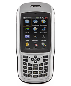
Topcon Positioning Group has introduced the T-18 handheld controller, which is designed to drive geopositioning, construction, mapping and vertical construction applications.
The controller includes a 3.7-inch sunlight-readable display with a 1-GHz processor, 1 GB of internal storage and up to 10 hours of battery life, the company said.
For data collection using Topcon’s MAGNET Field software, the T-18 controller offers a durable ergonomic solution with fast processing, a large screen, excellent connectivity and a long battery life.
Topcon MAGNET Field software offers a complete field solution for geopositioning professionals, enabling users to collect survey mapping data and perform construction and road layout using total stations, levels and GNSS receivers.
The T-18 features a 3.5G cellular modem for connectivity with Topcon MAGNET solutions for sending and receiving data to the cloud company account.
“The cellular option makes it easy to communicate with field crews when projects need to be changed or if important data is required back in the office. Additionally, the modem can be used for RTK (real-time kinematic) correction services,” Kerwin said.
Other key features include standard Bluetooth and Wi-Fi connectivity, as well as an IP65 rating for dust and water protection in demanding job site conditions.
My last column described the National Geodetic Survey’s (NGS) GPS on Bench Marks (BM) 2018 interactive web map, and provided an update and status report on stations observed in support of the 2018 GPS on BMs Program. It mentioned that all new data received by the cut-off date of Aug. 31 will be analyzed by NGS and, if appropriate, the results will be included in the next hybrid geoid model. This is a great opportunity to provide data that will help to improve the hybrid geoid model in your region. This column will provide an update and status report on stations observed in support of the 2018 GPS on BMs program and provide an example of how OPUS-shared results identified a station that may have moved since it was last leveled.
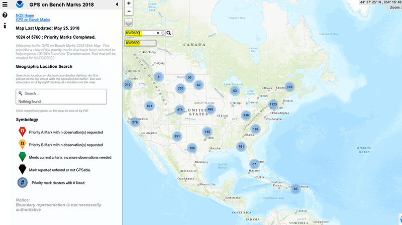
As mentioned in the last column, the GPS on BMs 2018 web page contains a link to a web map where users can determine which bench marks NGS would like users to occupy before the August 31, 2018, deadline. The web map also provides a list of the stations observed to date to ensure users are not wasting their time observing stations that already have enough repeat observations. NGS is updating the map weekly to reduce users occupying stations that already have enough redundant observations. The box titled “2018 Web Map” depicts the map update of May 25, 2018. The web map has a search feature so if the user knew a station’s PID, they could locate the station on the map. The box titled “An Example of Using the Web Map Search Feature” depicts the search feature using PID AW0690 (see highlighted section in the box).
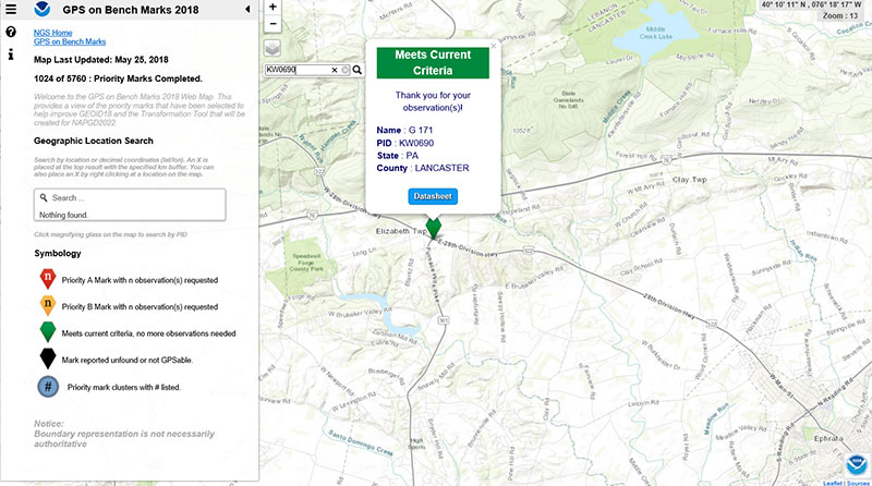
The box titled “Map After Searching for PID KW0690” depicts the map after searching for PID KW0690. As indicated by the symbol, the station meets the current criteria. That is, it has two GNSS-derived ellipsoid heights that agree within NGS’ criteria for use in evaluating and generating the next hybrid geoid model.
Map After Searching for PID KW0690
Click to enlarge.
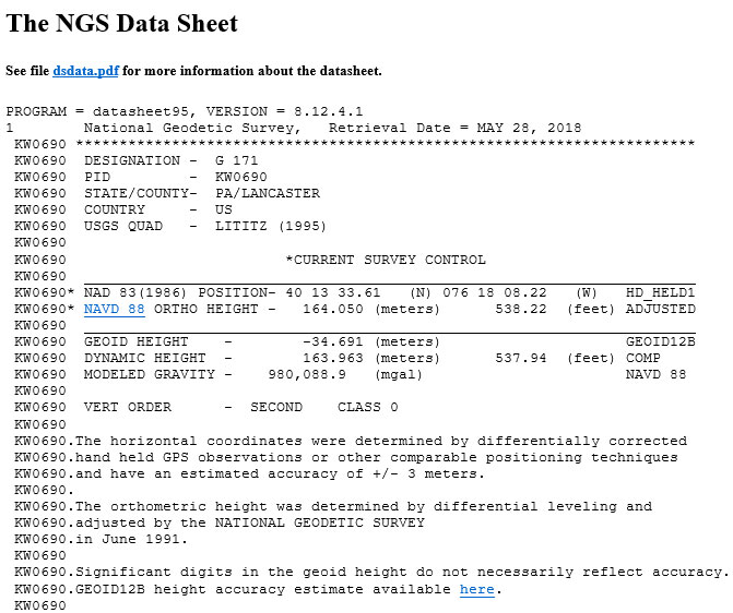
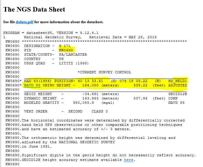
The user can continue to check on the link labeled “Datasheet” to obtain the latest data sheet for the station (see the box titled “NGS Data Sheet for KW0690”).
NGS Data Sheet for KW0690
Click to enlarge.
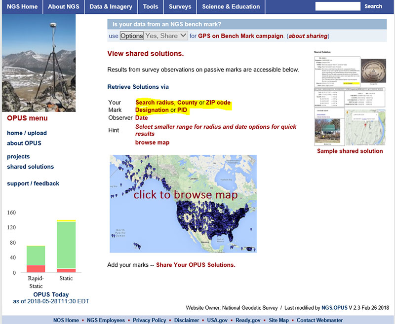
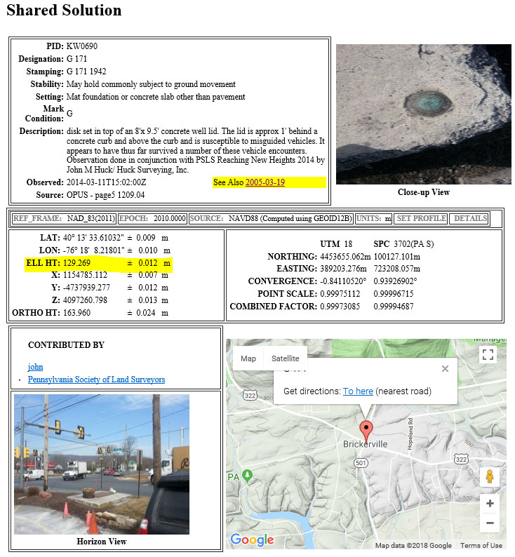
Next, let’s look at the OPUS shared results for the station (KW0690 – G 171). OPUS shared solutions can be found at this website. (see box tilted “OPUS Shared Solutions Web Page”).
OPUS Shared Solutions Web Page
Click to enlarge.
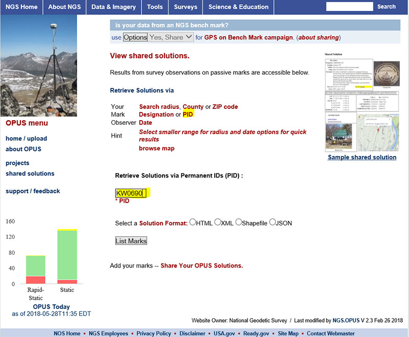
The user can search for a particular OPUS shared solution by checking on the PID option (see highlighted section on the box titled “Web Page After Clicking on PID Option.”
Web Page After Clicking on PID Option
Click to enlarge.
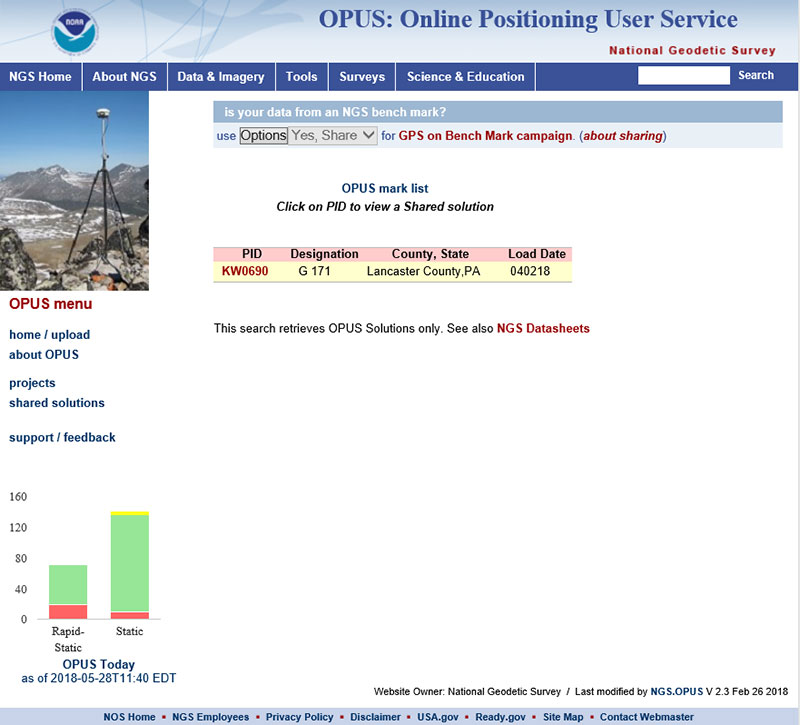
The box titled “An Example of Selecting an OPUS Shared Solution for a PID” depicts the output after clicking on the button labeled “List Marks.”
An Example of Selecting an OPUS Shared Solution for a PID
Click to enlarge.
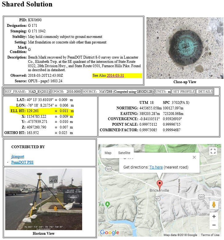
The box titled “The OPUS Shared Solution for KW0690 (2018-03-20)” provides the OPUS Shared solution for station KW0690 performed on March 20, 2018. The output provides the NAD 83 (2011) 2010.0 coordinates with error estimates.
The OPUS Shared Solution for KW0690 (2018-03-20)
Click to enlarge.
When there is more than one observation, the output file provides a link to the other observations. In this case, there was another shared solution on March 31, 2014 (see box titled “The OPUS Shared Solution for KW0690 (2014-03-31).”) The two solutions indicate the ellipsoid heights agree to 8 mm (129.269 m – 129.261 m). This is an indication that the station is a valid candidate to be considered for the development of the hybrid geoid model.
The OPUS Shared Solution for KW0690 (2014-03-31)
Click to enlarge.
The second OPUS Shared solution also indicates that there is a third observation (2005-03-19). Clicking on that link provides the NGS data sheet (see box titled “Excerpt from NGS Data Sheet for KW0690”).
Excerpt from NGS Data Sheet for KW0690
Click to enlarge.
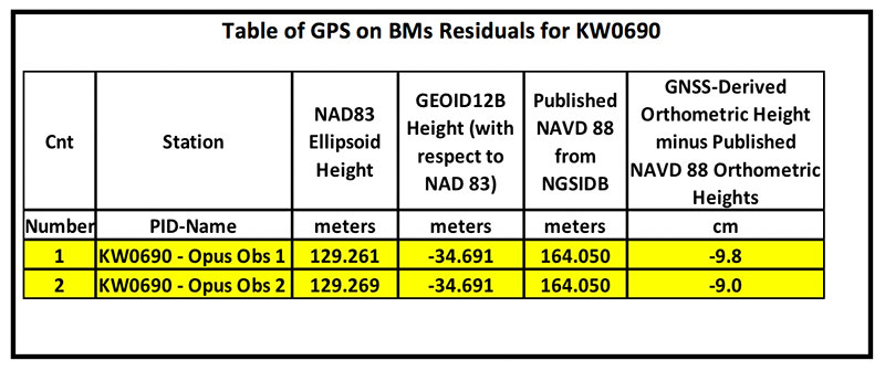
It should be noted that this station doesn’t have a published NAD 83 (2011) coordinate. The OPUS shared solutions provide the NAD 83 (2011) ellipsoid height and the NGS data sheet provides the published NAVD 88 orthometric height. Comparing the GNSS-derived orthometric height using the OPUS shared ellipsoid heights and GEOID12B indicate the station is inconsistent with published NAVD 88 orthometric height. The box titled “Table of GPS on BMs Residuals for KW0690” provides the GPS on BMs residuals based on using the latest hybrid geoid model GEOID12B. It was noted that the two ellipsoid heights agree to within 8 mm but the GNSS-derived orthometric heights using GEOID12B indicate that the two stations disagree with the published NAVD 88 height by almost 10 cm. This may be an indication that the station may have moved since the last time it was leveled. The question that needs to be addressed is should this station be used in the development of the next hybrid geoid model. In my mind, there are basically two school of thought on this topic. One, users that have used this individual station as control would like the hybrid geoid model to provide a GNSS-derived orthometric heights consistent with the published height of this station. If a surveyor followed the appropriate precise leveling procedures to check the validity of the station, that is, performed at least a two-mark leveling tie to ensure that the monument did not move, then they would want the model to be consistent with the published value. Two, if the station moved since it was last leveled, the hybrid geoid model would not provide the most accurate NAVD 88 height.
Table of GPS on BMs Residuals for KW0690
Click to enlarge.
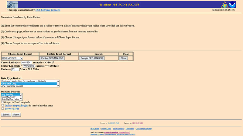
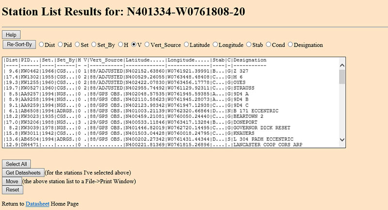
The next step is to analyze the GNSS-derived orthometric height using the latest experimental geoid model. Evaluating GPS on BMs stations nearby station KW0690 will help in determining if the station KW0690 has moved since the last time it was leveled. One way that users can determine stations nearby is to use NGS data sheet retrieval program using the option to retrieve stations by point radius. See box titled “Using NGS Data Sheet Point Radius Retrieval Option for KW0690.” The user enters a latitude and longitude value and a radius search in miles.
Using NGS Data Sheet Point Radius Retrieval Option for KW0690
Click to enlarge.
In this case, I entered the latitude and longitude of station KW0690, a radius of 20 miles (approximately 30 kilometers) and selected the option “GPS Stations Only.” The box titled “Output of NGS Data Sheet Point Radius Retrieval Option for KW0690” provides the output of the search. I sorted the stations by vertical control (“V”)
Output of NGS Data Sheet Point Radius Retrieval Option for KW0690
Click to enlarge.
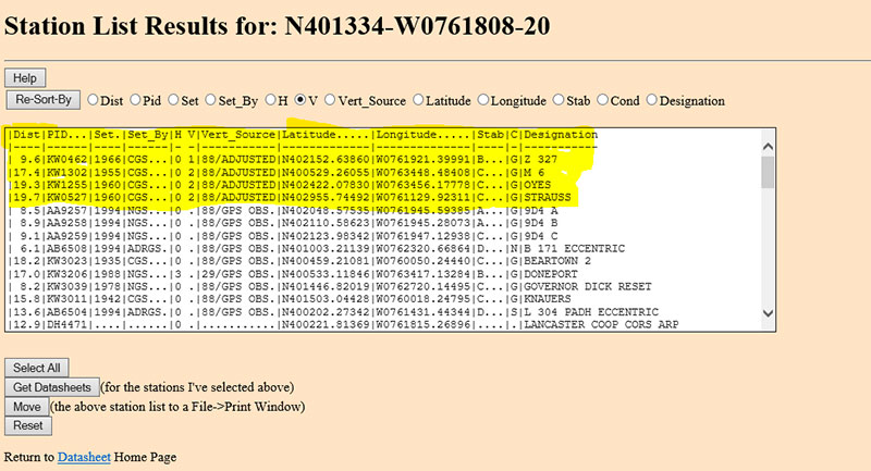
The four bench marks that also have GNSS-derived heights are highlighted in yellow in the box titled “Select the Bench Marks Based on NGS Data Sheet Point Radius Retrieval.” They are all within 20 miles (approximately 30 km) of the station KW0690. By analyzing the GPS on BMs residuals of these nearby stations we can determine if station KW0690 is consistent with its neighbors.
Select the Bench Marks Based on NGS Data Sheet Point Radius Retrieval
Click to enlarge.
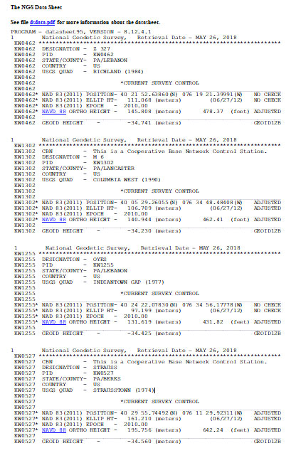
I retrieved the data sheets so I could get their published coordinates for the xGeoid17 web tool. See box titled “Excerpts from Data Sheets Based on NGS Data Sheet Point Radius Retrieval” for the data sheets.
Excerpts from Data Sheets Based on NGS Data Sheet Point Radius Retrieval
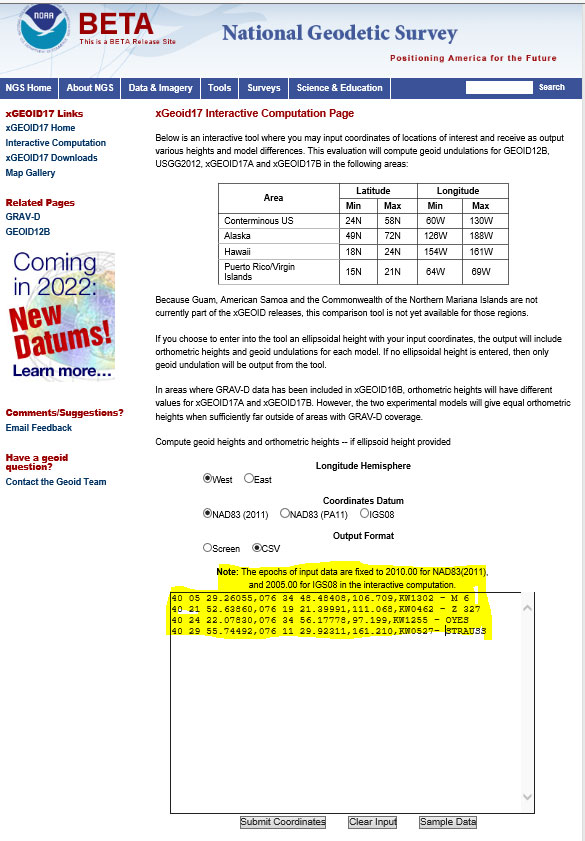
Once you have the stations that are located near the station you’re interested in you can proceed to the xGeoid17 website to obtain the latest information based on the scientific geoid model. I described this procedure in a previous column. See box titled “Using the xGeoid17 Web tool for Stations Nearby KW0690” for an example of the input to the tool.
Using the xGeoid17 Web tool for Stations Nearby KW0690
Click to enlarge.
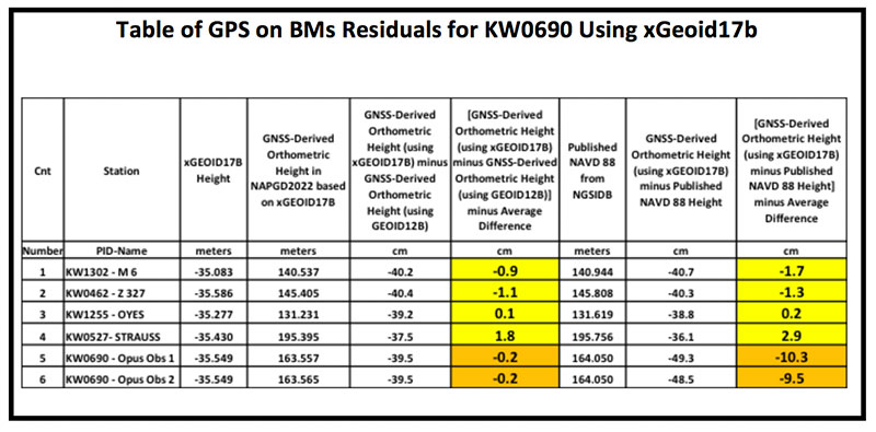
The table titled “Table of GPS on BMs Residuals for KW0690 Using xGeoid17b” provides a summary of the results from the xGeoid17 web page. The procedure used to compute the GPS on BMs residuals has been described in a previous column.
Table of GPS on BMs Residuals for KW0690 Using xGeoid17b
Click to enlarge.
Looking at the column labeled “[GNSS-Derived Orthometric Height (using xGEOID17B) minus Published NAVD 88 Height] minus Average Difference” indicate that the large difference that we noticed using GEOID12B at station KW0690 is also seen using the latest experimental geoid model xGeoid17b. Once again, this is an indication that the station may have moved since it was last leveled.
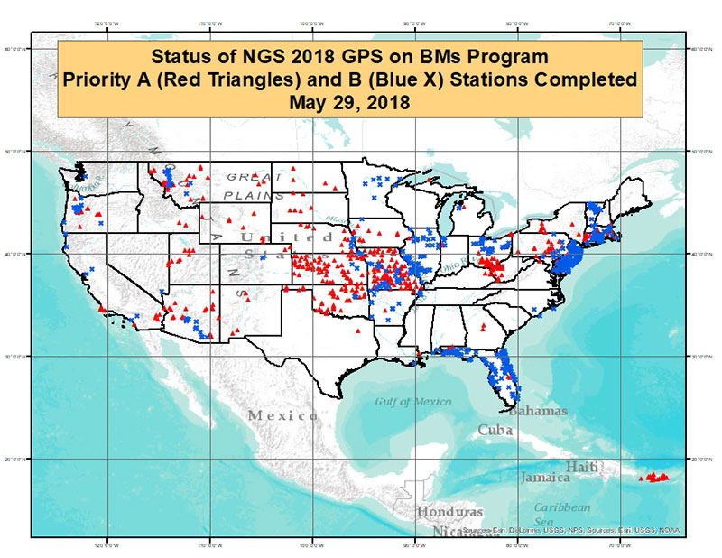
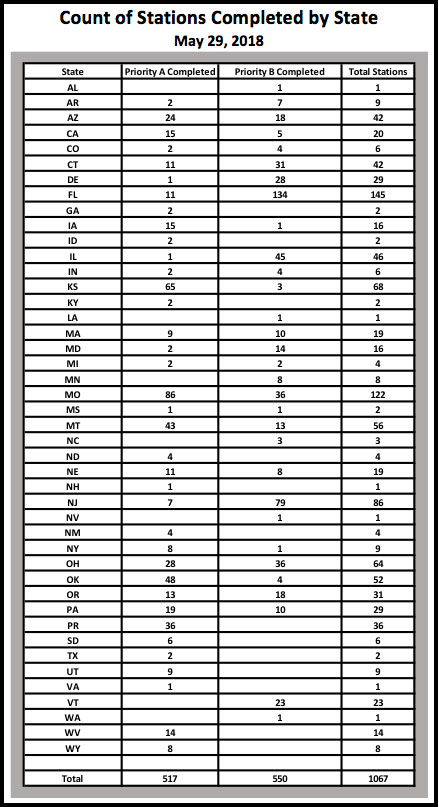
As of May 29, 2018, 1067 of the 5760 priority marks were completed. The box title “Status of NGS 2018 GPS on BMs Program as of May 29, 2018“ is a plot the stations that are labeled as completed and the box titled “Count of Stations Completed by State “ provides the number of stations completed by state. The red triangles are priority A stations completed and the blue “X” are priority B stations labeled as completed.
Status of NGS 2018 GPS on BMs Program as of May 29, 2018
Click to enlarge.
Count of Stations Completed by State May 29, 2018
The number of stations completed as of May 29, 2018, represents about 18.5 percent of the total number of stations that need to be observed. August 31, 2018, is only two months away. According to my latest search of the NGS website (June 3, 2018), 1098 stations are considered done. Hopefully, the number of completed stations will significantly increase during the next last two months. As I have explained in previous columns, there are many invalid GPS on BMs stations that may be used in the next hybrid geoid model unless more bench marks with valid NAVD 88 heights are observed with GNSS. This column provided an update and status report on stations observed in support of the 2018 GPS on BMs program and provided an example of how the OPUS Shared results as identified a station that may have moved since it was last leveled. This is your opportunity to help develop a current, valid hybrid geoid model in your area, and identify NAVD 88 bench marks that have moved since they were last leveled.
Victoria, Australia, is seeking to upgrade its digital cadastre, and is seeking industry interest. The Department of Environment, Land, Water and Planning (DELWP) has issued a market notification for industry on Digital Cadastre Modernisation (DCM).
DELWP has two related procurement processes in May and July 2018.
Request for Tender (RFT) 338298 for cadastral data back capture services was issued by DELWP on May 28, 2018.
A related Expression of Interest (EOI) will be released for the remaining stages of the DCM, (adjustment, integration and automation phases) on or about July 31. Potential suppliers will be asked to register their interest and outline their capability to deliver and innovate across one or multiple stages. Further procurement steps are anticipated in 2019.
Four inter-related stages of the DCM are expected to go to market. The tender notice described here relates to the first stage – back capture (RFT process 338298).
DELWP is upgrading the spatial accuracy of the state’s digital representation of property boundaries (the authoritative digital cadastre) for the state’s 3.3 million properties. An upgraded digital cadastre will deliver significant quality and efficiency improvements for sectors including land development, surveying, planning, utilities, emergency services and infrastructure development. The DCM will deliver spatial accuracy of up to 0.1 metre for urban and 0.5 metres for rural land.
STAGE 1 – Back capture: This stage will accurately capture specified data from PDF copies of registered plans and cadastral surveys into digital format LandXML files. This stage will also include the capture of particular features from aerial imagery.
The tender will seek proposals to deliver back-capture services for the entire state. Key information relating to the tender includes:
The scope should be broken into a minimum of three packages (a maximum of 1.3m parcels in any package), and the initial contract will be for only the first package.
Bidders should scope these packages in a manner which they believe will best meet DELWP’s objectives (around the most accurate and efficient delivery of the upgraded digital cadastre).
Subject to satisfactory delivery of the first contract, the successful bidder may be contracted to deliver the remaining packages.
Alternate proposals are encouraged, should bidders identify an opportunity to deliver better outcomes or innovation by combining the back capture stage with another DCM stage (outlined below).
Future procurement / future DCM stages (June EOI)
Three future stages of the DCM which will be outlined in the July EOI are briefly described below.
STAGE 2 – Adjustment: Initially, the analysis and validation of the back captured data obtained from stage 1 will be required. This will be followed by calculation and validation of the coordinates and uncertainties for all land parcel corners from back captured files and Victoria’s Survey Control Network. DELWP has bespoke software that may assist with the adjustment process, which can be licensed free of charge to the service provider.
STAGE 3 – Integration: Integrating the upgraded digital cadastre from STAGE 2 into the state’s authoritative map base (Vicmap). Note that the DCM upgrade coincides with the next re-tender of the ongoing maintenance contract for Vicmap, and it is possible there will be an opportunity for vendors to bid for both the integration stage and ongoing maintenance.
STAGE 4 – Automation: Enhancing DELWP’s existing corporate systems to fully automate the process of updating Victoria’s digital cadastre with new data (such as new sub-divisions) lodged in a digital format through SPEAR.
A fifth and essential aspect of the project relates to change management; this will run throughout delivery.
For more information contact [email protected], DCM program manager.
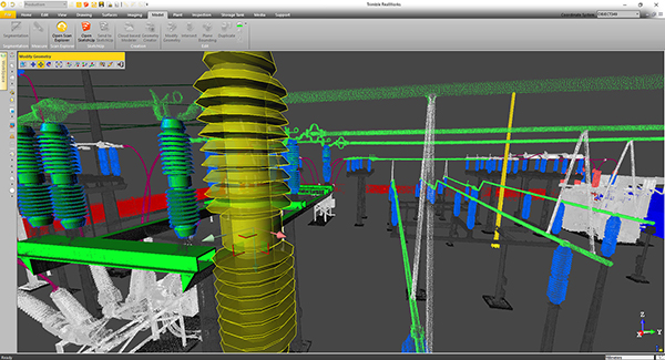
Trimble will release a new version of Trimble RealWorks, its all-in-one point-cloud software platform. The new version of Trimble RealWorks — featuring performance and user interface (UI) improvements — will be available for download June 19.
Changes include the following:
Batch processing workflows are now available to automate data processing for large datasets saving users time on projects.
New visualization and productivity tools include enhanced shading, improved registration automation and geometry editing. According to Trimble, the new tools enable customers to better understand project data and more easily create customer deliverables.
Enhanced multi-core processing for modern CPUs and added support for AMD Ryzen-based computers significantly reduces the processing time for registering and extracting scans.
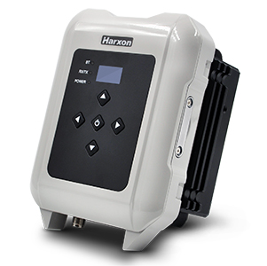
Harxon has introduced the smart eRadio, a member of its radio modem series. The eRadio is a long-range and power-efficient solution designed to support high-precision GNSS real-time kinematic (RTK) applications in surveying and precision agriculture.
Harxon eRadio is enabled with intelligent serial baud rate identification for different RTK devices. It can automatically identify RTK serial baud rate with a radio data cable and provide a plug-and-play form for easy connection between the eRadio and RTK, the company said.
Photo: Harxon
Due to its high transmitting power (5-35 Watts), transmission data can be up to 19200 bps/s over a connection distance of 50-80 kilometers, depending on the environment.
The eRadio offers surveyors an easy-to-use radio modem that provides dependable performance as either a base or repeater working with other Harxon radio modems in challenging environments. In the store and forward operating mode, eRadio receives messages, buffers the received data and transmits further to another substation.
The user programmable eRadio also supports the Bluetooth of APP to configure data and update radio status. Its diagnostic reporting software can realize the built-in reliability monitoring, such as internal temperature, environment status and battery level and channel inspection. According to the company, these features allow users to both anticipate and deal with potential issues efficiently.
In addition to compatibility with radio protocols by Trimble and Satel, eRadio is equipped with its unique ETALK communication protocol, which uses Harxon’s exclusive algorithms and advanced processors. Under the same conditions, ETALK protocol can significantly reduce the bit error rate of weak signals and the communication distance can be increased by 20 percent.
The compact, rugged eRadio is particularly well suited for heavy-duty outdoor use. It is designed for easy mobile use with an organic light-emitting diode display screen for demanding field conditions. The IP67 full metal cover provides dust and water resistance that keeps surveyors working with confidence and efficiency.
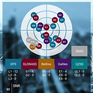
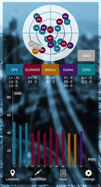
SXblue, also known as Geneq, has introduced its SXblue ToolBox, an Android application for SXblue GNSS receivers.
Using the SXblue ToolBox, receiver users can view and analyze the position data provided by the SXblue receiver and metadata related to its location. The user can send commands that enable or disable some features, including systems in use, mask angle or differential angle, and constellation in use, including GPS, GLONASS, Galileo, BeiDou and SBAS.
The SXblue ToolBox is also an NTRIP client capable of connecting to a NTRIP server for real-time kinematic (RTK) corrections and thus allow the receiver to issue very accurate location information. The application is able to record, save and transfer the raw data from the GNSS receiver, allowing post-processing activities on computers for surveying and geomatics professionals.
The application has been developed with special consideration for modern mobile device development and attention to user and dealer feedback, the company said.
The application includes a series of audible and visual alarms configurable by the user to determine the thresholds of the information provided by the SXblue GNSS receiver.
Main features of the SXblue ToolBox include:
Display of location information and quality of the position data
Skyplot of all-in-view constellations: GPS, GLONASS, Galileo, BeiDou, QZSS, SBAS
Log raw data
NTRIP/DIP client for receiving RTK corrections
Terminal to send commands and view the output data of the SXblue device
Audible and visual alarms
Activation of options and licenses via the application.
Eos Positioning Systems Inc. is partnering with enterprise mobile solutions provider CartoPac International to enable consumer smartphones and tablets to become professional-grade GNSS data collection and management devices for staking, inspections and more.
Eos manufactures the Arrow receivers for any smartphone or tablet. CartoPac develops enterprise utility software, including a mobile solution for asset management and data collection.
As utility and energy companies have begun to adapt smartphones as their primary data-collection devices, they have struggled to find integrated solutions that can tie the high-accuracy GNSS locations to their new and legacy assets. Their options were usually limited to onerous workflows of all-in-one handheld GPS devices or the hiring of specialized surveyors.
Eos and CartoPac partnered to integrate the Arrow Series with CartoPac‘s mobile software. This allows CartoPac users to bring submeter and centimeter location into their asset-management solution on either iOS, Windows or Windows Mobile devices.
One real-world example is the installation of an underground pipeline. A field user with CartoPac software and a high-accuracy Arrow receiver paired with an iPad was able to capture submeter asset data, scan the asset’s barcode, take photographs and populate the utility’s enterprise geodatabase in real time, the companies said.
With the right mobile solution, field crews can also be dispatched in no time to the same asset location to respond to emergencies or perform routine work orders and inspections.
“We saw our users struggling to get a good high-accuracy GPS solution within the iOS environment,” said Glenn Vlass, CartoPac co-founder and senior sales executive. “When you can say where an asset is spatially with such a degree of high confidence, that lowers your risk and improves your safety. Lower risk and improved safety are things every utility worker takes seriously.”
Eos and CartoPac plan to expand their deployment of high-accuracy mobile asset management to more utilities facing similar needs.
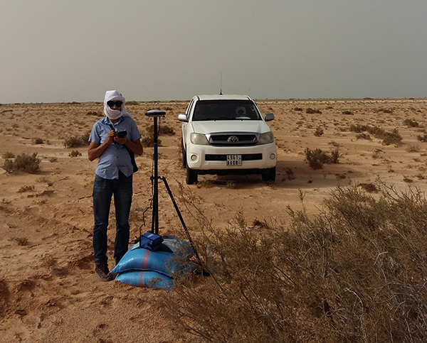
The Spectra Precision SP60 GNSS receiver has been selected to perform survey work for construction of a new 450-kilometer electric power transmission corridor.
Connecting Mauritania’s two largest cities, the capital Nouakchott and to the south Nouadhibou, the 225/90Kv transmission line parallels the Atlantic Ocean as it traverses the Sahara Desert.
The Mauritanian Electricity Company, SOMELEC, through its contracting company, awarded the sub-contract for surveying the transmission line and infrastructure to ETAFAT, a geospatial data acquisition and processing firm.
Difficult work conditions, including high heat (over 45 degrees Celsius) and the lack of existing control points were key factors in ETAFAT’s selection of the SP60 receiver. Because of the absence of existing benchmarks along the entire corridor, the SP60 RTX feature played a key role to ensure homogeneity in the coordinate reference frame between the two cities.
The RTX technology leverages real-time data from a global tracking station network with innovative positioning and compression algorithms to compute and relay satellite orbit, satellite clock and other system adjustments, transmitted to the SP60 via satellite or IP to deliver real time high-accuracy corrections, even in remote locations, the company said.
ETAFAT tested the SP60 data with RTX corrections and obtained consistently successful results. The geodetic survey was related to several ground control points (GCP) used in airborne survey. The measurement itself was conducted using two methods, dependently: the classical statistical method, and the RTK GNSS method. The SP60 met or exceeded the required +/- 15 cm order of accuracy.
According to baseline processing and adjustment reports, the SP60 delivered superior results under all conditions, and it did especially well under typical high temperatures of the Sahara Desert. Initialization was well within 5 to 10 seconds for RTK survey with radio signal coverage inside a 5 km radius.
As we approach the halfway point of 2018, one cannot help but notice the amount of technology that we use every day and how it affects our daily lives. While George Jetson isn’t whizzing by in a flying car to his glass condo in the clouds, we are utilizing an incredible amount of technology in normal life.
I can sit here typing on a computer or tablet that is many times advanced than the first one I used in junior high school and think nothing of it as futuristic technology has become the norm.
The old standard joke about technology used to be about cell phones and television remote controls; if you needed to figure it out, get your child or even grandchild to help. The youngsters were the majority that could embrace technology because they didn’t have past methods to confuse their ability to figure out how to work the new device.
A funny thing has happened along the way, though; those kids are now grown, and technology has advanced even further.
To help explain the names and timeframes of our generations, I found this chart that explained it all:
To help put this chart in context, the average age of the professional surveyor in the United States is 59 and solidly in the Baby Boomer category. But even with an average that high, there are still a significant number of surveyors in the Silent Generation as the economic downturn of the late 2000s has forced them to continue well into their golden years.
HOW SURVEYORS FIT IN THIS DISCUSSION
The surveying profession has suffered through the same generational challenge as the rest of society. The younger set that started out surveying with electronics have now graduated to much more complex yet capable machinery. Prior to the mid- to late 1970s, electronic technology did not play a role in most surveying operations and tasks. The professional surveyor was widely considered a boundary expert, map maker and establisher of topographic data, with the high-tech mapping work left to the government geodesists (see my July 2017 Survey Scene column).
Most surveyors who learned their craft prior to the electronic age were trained on the job or obtained an engineering degree through a program that may have offered a limited surveying curriculum. Surveying was a career for the outdoor type and required traversing rough terrain at times, as well as being able to withstand weather extremes.
THE NON-TECHNOLOGY GENERATIONS
As a second-generation surveyor, I was fortunate enough to have been exposed to land surveying literally as it was performed by our forefathers. While the tasks performed didn’t utilize a true Gunter’s chain and compass, they were completed with a modern transit and steel tape. The surveys we completed didn’t require high tech equipment as our manual procedures greatly exceeded commonly accepted positional tolerances.
A surveyor maps out boundaries for construction. (Photo: Bureau of Labor Statistics)
Most of the work performed by surveyors leading up to the early Baby Boomer generation was much simpler in theory but rarely easy to accomplish due to terrain, weather and the computations necessary to complete the boundary analysis. Traversing a parcel meant having a field crew of several people, often through brush and woods, and time consuming. A large parcel may be days or weeks of field to traverse around with most of it on foot. Once completed, the professional surveyor was tasked with often days of manual calculations, reduction of notes and determination of traverse closure. All the error from days of field work was then balanced through more hand calculations, usually by compass rule or transit rule, and hand drafted onto the final survey plat.
A similar story is followed with topographic and bathymetric surveys and creation of maps with existing conditions. Data collection performed to obtain locations and elevations of existing sites were by radial angle and distance or by grid method, with water depths being determined manually by use of lead lines. In the office this data is placed by manual drafting onto paper, sepia or vellum. Once elevations were plotted, contour intervals were determined by interpolation between each of these points. The creation of the contours was then drawn in by several methods, each with their own level of creativity by the drafter.
Because of the increased use and importance of electronic technology, data collection and advancements of the profession, today’s surveyor is faced with many more challenges than their predecessors. While the concepts for many tasks do follow the protocol for completing a multitude of survey duties, the way we go about collecting and analyzing the data is much more complex than in the past.
The need for our profession to identify these challenges and create opportunities for modern day surveyors is upon us, as our educational and training needs to be ramped up to stay current with demand. All professional surveyors, regardless of what generation they were born in, have filled or will fill an important role in society as expert measurers.
However, the rapid advancement of technology has exposed the lack of additional education and training necessary to keep our standing in serving the public’s health and welfare.
My point here is not that the work and tasks performed by past generations of surveyors was easier, but it did require more manual labor and less technical education and training. I liken the situation to automotive mechanics and how much more technology goes into working on a modern car versus vehicles of earlier generations.
Many mechanics tuned engines by “feel” with no recordable technology to tell them otherwise. I wouldn’t think of calling the expertise shown by past mechanics as inferior to today’s automotive mechanics; each has been trained to rely on different skills sets to work with completely different engines. Thus, I feel the same way in comparing different generations of surveyors. Different tools and methods require unique and specific training for the surveyor to perform at the highest level.
For example, look at the survey-related equipment, software and services within GPS World magazine; most of the articles, case studies and advertisements are for things not even considered five to 10 years ago. All these items require a different mindset of more technical and analytical processing, so the surveyor’s educational requirements and approach must adjust with the technology.
As time marches forward, the need for more advanced surveyors is reaching a critical point.
HOW TODAY’S SURVEYORS GET THE JOB DONE
Today’s surveying profession, including the field and office technicians, rely heavily on technology more than ever.
Many threads of advancing technology go into weaving the tapestry of modern surveying, with the primary material of GNSS being utilized throughout. I have written in the past regarding my thoughts on the single greatest advancement in surveying (see my May 2016 Survey Scene column) and my argument gets stronger with newer technology adding to the way we measure our world.
Here are some of the tasks in which the surveying profession uses GNSS as a basis of measurement and location, and why specific education and training is critical to proper execution:
Boundary surveys
Photo: Tim Burch
Like the surveyors before us, boundary establishment and re-establishment are the main responsibility of the profession. However, with GNSS, the ability to produce more location data has increased tremendously by reducing the need to perform intricate traverses through places when not necessary. It has also reduced the need to perform tedious traverse computations and adjustments; instead, least square adjustments are made to GNSS observational data to provide accurate results.
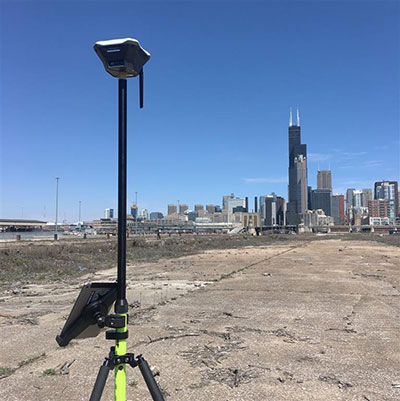
Topographic surveys
This data can be acquired by a combination of GNSS and conventional total station methods but is based upon geolocation information determined by primarily geodetic coordinates through GNSS solutions. Relying on GNSS data with no standard procedure for location and elevation verification can lead to major issues if not caught by an educated user.
All these methodologies, also known as remote sensing, have revolutionized mass data collection with the enormous amounts of information that can be acquired in a short amount of time. Each has specific functionality and limitations but rely on geolocation as a main attribute of the data. Because of the large data files that are created, the output is in the form of a point cloud rather than the traditional P,N,E,Z,D format normally utilized by surveyors. Like topographic surveys, this data typically relies on GNSS information for geolocation.
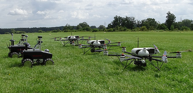
Photo: Simon Batzdorfer, Markus Bobbe, Martin Becker and Ulf Bestmann
Unmanned aerial and terrestrial systems
The newest of the data collection methodologies, the unmanned aerial vehicle (UAV) has taken the surveying world by storm. A good percentage of the new adopters (including me) utilize commercial grade multi-rotor units coupled with a high-resolution camera for orthometric photos and video clips of project sites.
While this method uses photogrammetry as its data collection method, it relies on GNSS for establishing ground control points (GCP) to establish geolocation to a known coordinate system. Higher end models incorporate RTK units to minimize the number of control points as well as utilizing lidar and/or hyperspectral modules for high end remote sensing.
Along with the airborne variety, land-based unmanned vehicles are starting to catch on as additional data collectors of open, navigable terrain. These autonomous devices are being equipped with lidar and cameras to augment aerial data in concert with UAVs to gather redundant information for quality checks.
As stated above, these remote sensing technologies, whether used statically or on an unmanned system, all create large point cloud data files that can be cumbersome to manage.
Bathymetric surveys
Many advancements have been made in producing measuring devices using sonar technology, including side- and multi-beam models for more detailed observations in varying conditions. GNSS plays a big role in this survey method due to the electronic ability to combine the depth readings of sonar instantaneously with geographic location. This improvement in data collection provides much more accurate and reliable information for the mapping of water bodies and passageways.
Bathymetric surveys are also getting in on the unmanned vehicle program as well with shallow draft autonomous watercraft being used in places where regular bathymetric vessels cannot go for survey data. More of these crafts are being implemented as they become more affordable.
What do these categories have in common? Most rely on specialized training and equipment to perform each specific task. Surveying has evolved past a “one size fits all” situation and demands that each sector of surveying have personnel trained for the job and have the right equipment to get it done.
A central figure in all these tasks is also GNSS technology; from survey-grade receivers to UAV’s, the tasks all revolve around geolocation.
HOW DOES THE PAST COEXIST WITH THE FUTURE?
The modern-day surveyor now has many different tools at their disposal that generations of surveyors before us couldn’t begin to fathom. The ability to perform at such levels of production and accuracy using new equipment and software is incredible and humbling. However, I’m afraid the technology is outpacing the profession. How many surveyors have taken the time to educate themselves on these enhancements? Because I think we are stretching ourselves too thin, now is the time for the professional surveying community to pause for a self-assessment of our abilities and what it will take to catch up with reality.
One of the biggest hurdles the surveying profession is facing are the lack of qualified technicians for positions both inside and out. The recession of 2008-2011 reduced the number of technicians in our field due to the lack of work being done in the economic downturn, but it also came at a time when technology was starting its upward run at increasing survey task efficiency. The downturn forced many surveyors and firms to make drastic cuts and reduce their investment in new technology, equipment and training to be more efficient. The surveying profession is now paying the price for that downturn with few adequately trained technicians along with licensed professionals not staying current with technological innovation and advances.
WHERE DO WE GO FROM HERE…?
Tim Burch with seventh-and eighth-grade students.
The professional surveyor must embrace technology by promoting the profession to more places beyond the four-year college. We must start in junior-high and high school in math, science and history classes encouraging students to investigate surveying as a career. We also need to support technical and vocational programs that can help introduce surveying as a possible path beyond their certificate or associate degree. One of the simplest topics I use in presentations is the discussion of GNSS technology and how it is built into almost everything the student sees. From their cellphone to the cars their parent’s drive, GNSS surrounds us with geolocation information to make our lives easier.
These technicians aren’t going to all come from a four-year university programs; they are going to come from those teenagers who spend hours honing their hand-eye coordination with video games and drone racing. They will also be the fluid minds writing code for the next big app, and the surveying profession needs to embrace them to incorporate their work in our geolocation world.
The professional surveying occupation has become much more than establishing boundaries of parcels; it now requires knowledge for mapping literally anything in the world. The challenge now is to find those who want to help us continue this surveying and mapping tradition. Fellow surveyors: are you up to the challenge to find your replacement?