Category: Survey

  • Unlicensed UAV services threaten survey profession


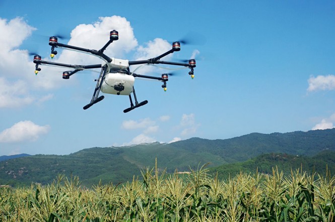
    Unless one has lived under a rock for the past few years, it is hard to miss the influx of unmanned aerial vehicles (UAV), otherwise known as drones. Once considered expensive toys for hobbyists, these vehicles have become the hottest ticket in town for gathering aerial photography and video with professionals and amateurs alike.

    Miniaturization of cameras, batteries and GPS receivers has allowed these former toys to become important tools for many different users. Like so many other pieces of equipment that have become more affordable to the general public, it still requires trained and licensed experts to produce data and deliverables from the UAV and applicable software. The trouble with all this rapid growth in technology is finding truly qualified users who understand that UAVs are just another tool to compete a task and not a replacement for the trained and licensed professional.

    Surveyors are facing this challenge every day as technology races ahead. The market for UAVs in the surveying environment seems to have blossomed along with the worldwide boom. Services utilizing UAVs by the unlicensed and non-professional vendor is becoming the largest threat to the surveying profession. Firms advertising “eliminate expensive survey crews” are becoming more visible in print publications and on the Internet as cheaper alternatives to the licensed professional surveyor.

    To fully understand the hazard these individuals and firms are presenting to the public, we shall first look at the laws that govern the surveying profession. For example, from my home state is an excerpt of Illinois Professional Land Surveyor Act of 1989 (225 ILCS 330/) referring to measurements to be performed by the professional land surveyor (see excerpt at the end of this column.)

    This act defines the tasks that are to be undertaken by the licensed surveyor. Like most professions, the surveyor is required to obtain a bachelor’s degree with a specific number of surveying classes along with four years of responsible charge of surveying duties. Illinois State Statutes also declare that those who offer these services without the proper licensing or training can be charged with Class A misdemeanor for a first offense, and guilty of a Class 4 felony for a second or subsequent offenses.

    Part of being a professional surveyor is also utilizing the proper tools of the trade. For the past 20 years, GPS has become the single greatest asset to the surveyor. It has allowed many tasks to be completed in greatly reduced time with more accurate results. The surveyor now has several different GPS tools to choose from, depending on the task. In my last column, “Data is the crop — GNSS used by surveyors and farmers,” I wrote of the varying levels of GPS receivers used by land surveyors and mappers for different types of data collection. Here is a brief review:

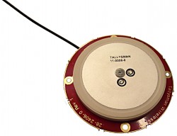
    Mapping Grade GPS (>= 3 meters)
    This handheld unit is primarily used for mapping utilities and improvements that don’t require high accuracy.

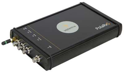
    Differential GPS (<= 1 meter)
    These systems are used by hydrographic surveyors for use in mapping lake and river bottoms as well as surveyors working in open pit mines producing existing condition maps and volumetric surveys.

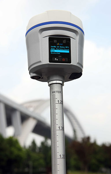
    Real time kinematic (RTK) (<= 2.5 centimeters)
    RTK systems range from base station/rover/radio combination to virtual reference systems (also known as “real time networks” or RTN) over cellular networks. These systems are prevalent with today’s surveyor as standard measuring equipment.

    While using any of these GPS types, surveyors have procedures for measuring and checking their results in a precise and particular manner. Most surveyors primarily use RTK or RTN-based systems for all of their work and require continuous data verification throughout the collection process. Control points and monuments are utilized for quality checks and verification in order to assure the work being performed meets the required accuracy standards.

    The integrity of the data is closely guarded by the surveyor as their duty to performing the job correctly and efficiently. These policies and procedures are also paramount to the work being performed remotely by a UAV under the direction of a surveyor, so the service being provided is professional.

    The consumer (and small business) side of the UAV industry, however, is much different. The costs vary from $100 and up, depending on rotors, batteries and camera capability. One of the main advances has been the implementation of GPS receivers but with much lower accurate positional information.

    Like the dashboard GPS screens in cars and now GPS on every smartphone, John Q. Public assumes that the geographic positions provided by the UAV receivers are very accurate and have little to no error. On the contrary, most GPS receivers in these units provide autonomous positions with horizontal accuracies in the 2-5 meter range (at best) and can follow a preset flight path created on a smartphone or tablet.

    Also, these UAVs and software have also opened the door to new opportunities for entrepreneurs everywhere. The high-definition cameras with capabilities including 4K video and 15-20 megapixel images allows the tech-savvy user to fly and collect aerial photography and video that rivals companies with a fleet of aircraft and expensive cameras. These images are used with software that stitches multiple shots together based upon GPS location and common elements in each image to create 3D models for terrain analyzation. No “on the ground” data verification or survey measurements are utilized to confirm the image’s integrity or scale.

    Many vendors are also offering verification of quantities in gravel pits and mining operations utilizing the volume calculation modules within the software. These images may be a pretty picture but for surveying purposes, they don’t pass the sufficient accuracy tests.

    In contrast, survey-specific UAVs and software will cost $25,000 and up, but are designed to provide the necessary accuracy required to perform a professional surveying task. Flight planning with state plane coordinate systems are most common, as these systems directly relate to the surveys being performed in conjunction with the aerial flights. Panel points are set for identification within the images to verify known distances and accuracy checks.

    Volume quantities can also calculate with greater accuracy based upon these methods and procedures. Surveyors are also using the technology to perform ongoing as-built conditions in order to provide construction sites progress reports of installation of improvements. All of these tasks are possible with the higher accuracy capability of the survey-grade UAV under the direction and guidance of the professional surveyor.

    The surveyor, with the professional knowledge of geographical and state plane coordinates, also understands the boundaries of “no fly zones” and the use of geofencing by the U.S. government and the UAV manufacturers. As these zones become more prevalent, knowing how to honor and adapt to them is already a staple in the surveyor’s tool bag.

    The State of Illinois is currently drafting rules for UAV operation that will coincide with the proposed rules due from the FAA in June 2016. While most concern from the public is in regard to privacy and public safety, I am concerned as a professional surveyor that the current trend of use of UAVs by unlicensed professionals for surveying and engineering services will harm the public as much as the other issues combined. Engineering designs that are based upon data collected by unlicensed professionals should not be accepted by governing bodies in an effort to protect the public. Licensed surveyors, utilizing the proper tools (including survey grade GPS and UAVs), provide the accurate data for these designs.

    Technology has made the UAV an exciting toy for most and a new tool for some industries, including surveying. Like any tool, proper use and instruction is necessary for the safety of the operator and the public. The UAV does not make its owner a surveyor, just as buying a pipewrench doesn’t make its user a plumber.

    For more information on UAV use and procedures, go to Know Before You Fly.


    Excerpt of Illinois Professional Land Surveyor Act of 1989

    (225 ILCS 330/5) (from Ch. 111, par. 3255)
    (Section scheduled to be repealed on January 1, 2020)

    Sec. 5. Practice of land surveying defined. Any person who practices in Illinois as a professional land surveyor who renders, offers to render, or holds himself or herself out as able to render, or perform any service, the adequate performance of which involves the special knowledge of the art and application of the principles of the accurate and precise measurement of length, angle, elevation or volume, mathematics, the related physical and applied sciences, and the relevant requirements of law, all of which are acquired by education, training, experience, and examination. Any one or combination of the following practices constitutes the practice of land surveying:

    (a) Establishing or reestablishing, locating, defining, and making or monumenting land boundaries or title or real property lines and the platting of lands and subdivisions;

    (b) Establishing the area or volume of any portion of the earth’s surface, subsurface, or airspace with respect to boundary lines, determining the configuration or contours of any portion of the earth’s surface, subsurface, or airspace or the location of fixed objects thereon, except as performed by photogrammetric methods or except when the level of accuracy required is less than the level of accuracy required by the National Society of Professional Surveyors Model Standards and Practice;

    (c) Preparing descriptions for the determination of title or real property rights to any portion or volume of the earth’s surface, subsurface, or airspace involving the lengths and direction of boundary lines, areas, parts of platted parcels or the contours of the earth’s surface, subsurface, or airspace;

    (d) Labeling, designating, naming, or otherwise identifying legal lines or land title lines of the United States Rectangular System or any subdivision thereof on any plat, map, exhibit, photograph, photographic composite, or mosaic or photogrammetric map of any portion of the earth’s surface for the purpose of recording the same in the Office of Recorder in any county

  • Topcon announces robotic-based system for concrete paving

    Topcon Positioning Group is offering a local positioning system (LPS) for concrete paving. The LPS Paving System is designed to provide a stringless paving solution in conditions when GNSS signals are blocked or unavailable.

    It uses multiple Topcon PS series robotic total stations — tracking two prisms mounted to the concrete paver — for steering and elevation control.

    “This robotic-based system does not encounter sensor outages from bridges and tight paving lanes, including sound walls and active traffic on a mainline project, which could be a problem using GPS,” said Brian Lingobardo, Topcon­ 3D road construction systems manager.

    The LPS system uses the new MC-i4 receiver with LongLink for local communications between the robots.

    “Multiple robots can be setup ahead of time for seamless transitions and without the need to stop to switch total stations. Often a contractor needs to minimize stoppage to achieve tight ride specifications on projects such as tollways,” Lingobardo said.

    “The robots provide very accurate data to the paver’s control system and in turn the results are very impressive,” said Lingobardo.


  • Synergizing smartphones’ onboard GPS capability with KML files

    By Jay Satalich, P.L.S., GISP

    At Caltrans District 7 in Los Angeles, we use the onboard GPS capability of smartphones to navigate in real time to the locations of proposed aerial targets and National Geodetic Survey (NGS) control stations.

    Keyhole markup language (KML) files are created in the office using desktop GIS, then downloaded to smartphones for use in the field. We create KML files specifically for use by our surveyors during every aerial mapping project within Los Angeles and Ventura counties.

    FIGURE 1. Highway Interchange displayed on a smartphone using Google Earth App for Android, (ground targets in blue, flight information for pilots in red and green). Airborne GPS positioning aids in controlling aerial photography as the pilot navigates from exposure to exposure. A flight management system automatically triggers the camera or sensor once it reaches the exposure station in the air.
    FIGURE 1. Highway Interchange displayed on a smartphone using Google Earth App for Android, (ground targets in blue, flight information for pilots in red and green). Airborne GPS positioning aids in controlling aerial photography as the pilot navigates from exposure to exposure. A flight management system automatically triggers the camera or sensor once it reaches the exposure station in the air.

    KML is an extensive markup language (XML) notation for expressing geographic annotation and visualization within Internet-based, two-dimensional maps and three-dimensional Earth browsers. KML was developed for use with Google Earth — originally named Keyhole Earth Viewer.

    The aerial target layer also shows the proposed locations of stereo model limits on the smartphone. A stereo model is the overlapping portion of two adjacent aerial images. Each typically has a 60 percent overlap with its adjacent image, so it can be viewed and mapped in stereo. The ground control is combined with the airborne GPS to provide the orientation of the individual exposures, and it establishes the coordinate space of that imagery for any subsequent products.

    Having the stereo model limits as a data layer becomes a handy piece of information in the event an aerial target must be relocated because of unfavorable field conditions. The heads-up capabilities of GPS aboard the smartphones and KML files can also show the easiest path to reach either target location or control stations. The NGS control station layer hyperlinks to the NGS website, so the field surveyor always has the recovery note available in an electronic format.

    The field surveyors are also given hardcopy maps of the target locations and control stations, but those are now only used as a backup to the KML files loaded onto the smartphones.

    FIGURE 2. Phone Screen with station description from NGS database (above).
    FIGURE 2. Phone Screen with station description from NGS database (above).
    FIGURE 3. The user arrives here via a hyperlink from another screen (FIGURE 2).
    FIGURE 3. The user arrives here via a hyperlink from another screen (FIGURE 2).

    We have found that leveraging the onboard GPS capability of smartphones with GIS-based data layers in the field has increased production. Using smartphones provides the surveyors with information more concisely and clearly. This information enables surveyors to make better decisions in the field.

    One example is identifying inaccessible areas. If the field surveyor sees that an aerial target can be moved to a different location that provides easier access, it can save time and guesswork.

    This information is also valuable in rugged areas because the field surveyor may need to identify the location of hiking trails or while surveying in the desert, or identify the location of aerial targets in areas that are either lightly inhabited or have few landmarks. The project surveyor can tailor datasets specifically to project needed by the field surveyors.

    Once the aerial targets have been placed and the NGS control stations recovered, the field surveyors then position the aerial targets and control stations using carrier-phase GNSS. This gives us the centimeter-level accuracy needed to control the aerial photography during our mapping projects.

  • GNSS echo sounder guides medical ship through uncharted waters

    An Australian company that manufacturers GNSS echo sounders aided the aiders — leading a medical ship through uncharted waters in Papua New Guinea.

    The CEESCOPE echo sounder enabled the ship to reach volunteers who were working to save the life of a newborn.

    The ship, operated by YWAM Medical Ships Australia (YWAM MSA), visits remote villages in Papua New Guinea, giving communities access to life-saving medical and dental services. The village locations are accessed by river, and while often there is adequate tide information to help navigate, there are no available charts or bathymetry data for the passages upriver.

    Without a navigable route to follow, the medical ships simply could not travel to locations where help is needed the most.

    To solve this problem, YWAM decided to make its own charts, with help from CEE HydroSystems. Using a small, fast launch equipped with a CEESCOPE single-beam echo sounder and GPS hydrographic survey system, YWAM volunteer and master mariner Jeremy Schierer set out to find safe routes through vast river deltas ahead of the medical ship.

    While surveying at high speed to maximize the area covered, Schierer executed reconnaissance patterns along the river while continuously updating the hydrographic survey plan based on the results seen.

    Survey data gathered and processed in HYPACK acquisition software were exported to the navigation system of the ship to provide waypoints marking the safe passage route along the river. Used with available and observed tide data, the navigator of the vessel could confidently travel upriver without the risk of grounding.

    The CEESCOPE is a one-box survey system that can be swapped between the two available 4.2-meter and 5.2-meter boats. It can be used without an acquisition PC on the survey launch if needed — all data recorded on the internal memory, and can run on its own battery power for an extended duration. With operation in remote areas on small boats, reliability and usability were key for YWAM.

    YWAM also used the CEESCOPE with HYPACK from the wheelhouse to navigate the ship along the surveyed routes on custom electronic charts.

    In the third year of YWAM’s operation in Papua New Guinea, Schierer recorded a staggering 3,400 kilometers (2,000 miles) of bathymetry to help navigate the Pacific Link. All of the rivers were uncharted before the ship traveled upstream. With incomplete tide-station coverage, determining the ship’s path was a complex calculation. Despite this, and complicated by a bore tide, YWAM was able to take its vessel 75 kilometers upstream in the Bamu River, Western Province, without published charts.

    However, the most startling example of the benefit of the YWAM hydrographic survey approach took place in the second year of operation.

    “Baimuru is up the Pie River from Port Romilly in the Gulf Province,” Schierer said. “The only previous known route took us about four hours through the rivers and required high tide and daylight.

    “We went out with the CEESCOPE to see if we could find an alternate and more direct route to the open sea. We left the ship just before sunrise and went as far as 8 nautical miles off the coast to confirm a good passage — and we found one that was deep enough.”

    Instead of leaving when scheduled, the ship received an emergency call from the medical center about 300 meters away on the shore, where there is no electricity or running water.

    “A lady had just given birth, and they were requesting attendance by our doctor and midwife. Evidently the baby was born in the canoe on the way to the medical center, and for some time the baby lay in the bottom of the canoe.

    “By the time we unsecured our small boat and got the medical team ashore, the baby was 35 degrees Celsius and not warming up. Our medical team was able to assist in warming the baby and reported that if we had not been there, they were quite certain that the baby would not have survived the night.

    “The only reason we were still there was because we had the CEESCOPE and had been able to find another route. We’ve charted more than 1,200 kilometers with the CEESCOPE so far, and it is making a huge difference,” Schierer said.

    The track of the medical ship on the previously uncharted Bamu River.
    The track of the medical ship on the previously uncharted Bamu River.

    Based in Sydney, CEE HydroSystems opened an office in San Diego, California, in late 2015, to serve the United States and Canada. The company specializes in RTK GNSS-enabled precision shallow water hydrographic echo sounders. Its products are aimed at surveyors conducting shallow water bathymetric surveys.

    “For inshore hydrographic surveys of water bodies such as canals, lakes, rivers or industrial water impoundments, survey firms inexperienced in hydrographic methods often have to resort to conventional and laborious processes using sounding lines, range poles or basic sonar equipment,” said Peter Garforth, CEE HydroSystems managing director. “Our CEESCOPETM survey system puts a RTK GNSS solution and precision echo sounder into a compact single package, allowing surveyors to vastly improve productivity on these surveys.”

    The CEE range of echo sounders with GPS was first developed to offer surveyors a one-box solution to reduce hardware setup time and the need for interconnecting components.


    Portable echo sounder

    The CEESCOPE uses a built-in RTK GNSS receiver and UHF radio modem to acquire RTK-quality position and elevation that is used in hydrographic surveying software to output xyz point-cloud data files of bottom elevations in local coordinates and datums. In RTK mode, the CEESCOPE can be directly connected to the local UHF base station radio. The internal CEESCOPE GNSS receiver provides accurate position data at 1–20 Hz, and the single-beam echo sounder records soundings at up to 20Hz.

    Both data streams — plus any ancillary measurements fed into the unit such as heave, pitch and roll — are precisely time-tagged using a 1PPS signal and then recorded on the CEESCOPE internal memory. Simultaneously, the data are output to an acquisition PC or tablet.


  • TerraGo and Eos Positioning partner on next-generation GPS/GNSS solutions

    TerraGo and Eos Positioning partner on next-generation GPS/GNSS solutions

    Eos Positioning's Arrow 200 Bluetooth receiver supports Hemisphere's Atlas correction service.
    Eos Positioning’s Arrow 200 Bluetooth receiver.

    TerraGo and Eos Positioning Systems have entered a collaboration to combine the TerraGo Edge mobile GPS data-collection platform with the Eos Arrow line of sub-meter and centimeter accuracy receivers. The combination delivers a modern, cloud-based, real-time data collection capability, according to a TerraGo press release.

    While the working environments and the projects are very different, customers in for water utilities, energy, survey and engineering are using TerraGo Edge and Eos Arrow receivers to replace traditional GPS handhelds for cost-savings and improved productivity.

    Enmapp, a pipeline inspection company based in Canada, was able to cut hardware costs by 85 percent while capturing sub-meter data in real-time, eliminating all the costs of post-processing handheld data.

    Summit Engineering, a Colorado-based engineering and land surveying firm, was able to reduce hardware costs by over 50 percent and improve productivity by more than 30 percent while surveying power lines in Minnesota for one of the country’s largest energy companies. Similar performance improvements and cost reductions are reported by joint customers in water utilities, forestry, engineering, agriculture and environmental operations, TerraGo said.

    “When we talk about Eos Arrow, we’re not simply pairing their receivers via Bluetooth, there are millions of apps that do that without any meaningful integration,” said Dave Basil, VP of products and services at TerraGo. “We interoperate with their receivers at the software level to ensure our customers get the full real-time GPS data set so they can monitor, alert and capture data that meets the highest accuracy and quality standards. For customers, it’s as simple as Bluetooth pairing, but we’ve done the work to turn their phone or tablet into a survey-grade receiver.”

    “TerraGo and Eos Positioning are strategic technology partners,” said Jean-Yves Lauture, chief technology officer of Eos Positioning Systems. “This means that our collaboration goes beyond simple marketing and includes sharing core technology for the benefit of our customers. For example, we have been able to share Eos software components, which TerraGo has built into the Edge app. This integration provides the full fidelity monitor and lossless capture of NMEA data from the Eos receivers, including the Arrow 200.”

  • Sokkia’s SHC500 field controller designed for surveying

    Sokkia has introduced its new SHC500 field controller for construction and surveying applications. It is designed to provide operators a compact handheld option with numerous features and benefits, including a 4.3-inch touchscreen display and optional 5 MP camera with built-in LED flash.

    The SHC500 is designed for the professional operating MAGNET Field, Site and Layout software. The data controller works with all Sokkia GNSS receivers and total stations, and meets or exceeds all field application requirements.

    “With a sunlight-readable screen, even in bright conditions the controller is perfect for modern project sites,” said Ray Kerwin, director of global surveying products. “It is built rugged — waterproof up to one meter with an IP68 rating — securing the unit and optional built-in LED flash camera and 8GB flash storage.

    “The SHC500’s optional internal cellular modem allows operators to send and receive data through the MAGNET suite of software solutions. Field crews can easily communicate when projects need to be changed or if important data is required back in the office,” Kerwin said.

    Additional features include standard Bluetooth and Wi-Fi connectivity, 23 control buttons with numeric input, and a capacitive-touch interface.

  • Water utility deploys TerraGo Edge to improve service

    The City of Sebring, Florida, has deployed TerraGo Edge for utility asset inspection and management. According to a TerraGo press release, using its software has enabled the city to cut costs, bring surveys in-house and improve response times for repairs.

    Like thousands of water utilities across the United States, the City of Sebring Utilities Department is tasked with providing a safe and reliable water supply, while managing all the dispersed assets of the water distribution and wastewater systems. To do this, Sebring needs to constantly locate, map and inspect the assets to maintain service levels and operations.

    To avoid the high cost of traditional GPS technology and services, Sebring researched mobile products to see if other organizations had field success using iPads and iPhones to do the work. They found TerraGo Edge could deliver custom forms, CAD diagrams and survey-grade accuracy.

    “The deployment of TerraGo Edge saved the City of Sebring the expense of a traditional GIS and GPS solution, as well as the cost of surveying services, which could have run over $300,000,” said Mark Kretz, Water Plant Operations. “On a day-to-day basis, the biggest benefit is that we get the ease of use of an iPad, and didn’t have to buy and utilize proprietary GPS handhelds, which are more complex and vastly more expensive.”

    To learn more about the City of Sebring customer success story, download the case study here.

  • Topcon introduces new data controller for surveying

    Source: GPS world staff
    Topcon’s FC-5000 data controller.

    Topcon Positioning Group has added the FC-5000 to its line of data controllers for construction and surveying professionals. The 7-inch sunlight-readable display field controller is designed to provide operators a larger, more versatile and faster handheld computer for the modern construction site.

    “At 7-inches, the FC-5000 has the largest handheld data controller screen in our product line,” said Ray Kerwin, director of global surveying products. “The display has a capacitive touch interface — with finger, glove, small tip stylus and water capable options — that is optically bonded to increase visibility. With the press of a key, a user can change the orientation of the screen from portrait to landscape to increase visibility when viewing maps or drawings.”

    The controller is compatible with all Topcon GNSS receivers and total stations — operating MAGNET Field, Site and Layout software.

    “The FC-5000 comes with two built-in cameras — an 8 MP camera with autofocus and LED flash for field photography — and a 2 MP camera on the front for video meetings. With 64GB of flash storage, users can store hundreds of photos in the unit, which can be easily transferred to any computer or USB stick,” Kerwin said.

    Additional features include an optional 4G LTE cellular modem, internal GPS navigation, Bluetooth and Wi-Fi, and a battery life of 10-plus hours.

  • Launchpad: Mapping book, anti-drone system

    Launchpad: Mapping book, anti-drone system

    OEM

    The Septentrio PolaRx5 GNSS receiver.
    The Septentrio PolaRx5 GNSS receiver.

    GNSS receiver

    Next generation for precise scientific and geodetic applications

    The PolaRx5 offers 544 hardware channels for robust and high-quality GNSS tracking. The receiver supports all major satellite signals including GPS, GLONASS, Galileo and BeiDou, as well as regional satellite systems including QZSS and IRSS. Septentrio’s Advanced Interference Mitigation (AIM+) technology enables it to filter out both intentional and unintentional sources of radio interference, from narrowband signals over high-powered pulsed signals to chirp jammers and Iridium interferers. Septentrio’s APME+ multipath mitigation technology eliminates short delay multipath without introduction of bias and guarantees superior measurement quality. The user can deactivate APME+ to obtain unmodified measurements.

    Septentrio, www.septentrio.com


    Bentoni_2_antenna_patterns-W

    Flexible antennas

    Folding design for plug-and-play integration

    Bentoni is a positioning antenna for all of the global public satellite constellations: GPS, GLONASS, BeiDou and Galileo. It is designed to be used in trackers, portable devices, network components, drones and wearable electronics. It offers high performance and maintains good isolation in situ within a device. Bentoni is a flexible FPC antenna in Antenova’s flexiiANT product range. They are supplied with an I-PEX MHF connector and a 1.13 mm RF cable in a choice of three lengths. They can be folded to save space in operation within a device, with the aim being plug-and-play simplicity. The antennas are self-adhesive mounted so that they can easily be fixed inside an electronic device.

    Antenova, www.antenova-m2m.com


    The Tallysman TW2926.
    The Tallysman TW2926.

    L-Band antenna

    OEM antenna can be custom-tuned

    The Tallysman TW2926 antenna is an unhoused OEM version of the TW2920, designed for simultaneous reception of L-band correction signals and all of the upper band GNSS signals, including GPS L1, GLONASS G1, Galileo E1 and BeiDou B1. The TW2926 is 56 millimeters in diameter and has four drilled plated holes for secure mounting within customers’ products. It can be custom tuned to ensure optimal performance within an enclosure. The 1-dB bandwidth of both the TW2920 and TW2926 covers 1525–1559 MHz for the L-band downlink and 1559–1610 MHz for the upper-band GNSS. The LNA provides 28-dB of gain. The antennas employ Tallysman’s Accutenna technology, which provides strong cross-polarization rejection for greatly improved multipath rejection, low axial ratio and tight phase center variation.

    Tallysman, www.tallysman.com


    Marvell-NFC

    NFC controller

    Enables tiny antennas for mobile, IoT, wearables

    The Near Field Communication (NFC) 88NF100 controller with active load modulation (ALM) is desgined to support the smallest antenna sizes critical to mobile, the Internet of Things (IoT), wearable and automotive applications. Adhering to NFC Controller Interface (NCI) Technical Specification version 1.1, the 88NF100 provides an extended operating range and is extremely energy efficient to enable extended battery life for power-critical applications. ALM technology supports the smallest antenna sizes to enable OEMs to implement NFC capabilities into small form-factor designs. The controller has extremely low power operation in polling mode to provide increased battery life for power critical applications and three single-wire protocol (SWP) interfaces to secure element (eSE) devices for secure payments. The two-pin antenna interface supports a maximum distance of two meters between the chip and antenna.

    Marvell, www.marvell.com


    Survey & Mapping

     mapping design bookIntroduction to Mapping Techniques

    Available as print or ebook

    Designing Better Maps: A Guide for GIS Users, second edition, is an updated and comprehensive guide to creating maps that communicate effectively. Cartographer Cynthia A. Brewer covers the basics of good cartography, including layout design, scales, projections, color selection, font choices and symbol placement; she also describes her ColorBrewer application, an online color selection tool. The second edition includes a new chapter on map publishing. One reviewer wrote, “It is also worth a look by experienced cartographers who seek a refresher and a few new tips.” Brewer is a professor and chair of the Department of Geography at Pennsylvania State University and map and atlas design consultant.

    Esri, esripress.esri.com


    Arrow-Eos-android-v2-W

    RTK NTRIP Android app

    Eos Pro Tools is tightly integrated with google map

    Eos Pro Tools is a comprehensive RTK NTRIP app for Android that works with its Arrow line of RTK GNSS receivers. An Arrow GNSS receiver combined with the NTRIP app turns an Android smartphone or tablet into a powerful data collector capable of recording 1-centimeter accurate GIS data in real-time. The app, named Eos Tools Pro, has user-configurable audible and visual alarms to alert the user of high PDOP, lost RTK correction, unacceptable correction age and several other important metrics. It supports all current and future constellations (GPS, GLONASS, Galileo and Beidou). Detailed satellite information such as a skyplot that plots each visible satellite, whether it’s being used or not, and signal strength bar graphs from each constellation are also displayed. Finally, a terminal screen displays the NMEA data flowing and allows the user to send commands to the receiver.

    Eos Positioning Systems, www.eos-gnss.com


    ALGIZ-RT7-rugged-tablet-Android-jobsite-construction-O

    Rugged field tablet

    Lightweight, ergonomic design for the mobile workforce

    The 7-inch Algiz RT7 Android tablet is fully rugged, meeting stringent MIL-STD-810G U.S. military standards for protection against drops, vibrations and extreme temperatures. Its IP65 rating means that it’s waterproof as well as fully sealed against sand and dust. The tablet comes with a built-in accelerometer, gyroscope and e-compass as well as a stand-alone u-blox EA-7M GPS receiver for navigation, along with built-in Qualcomm IZat location services.

    Handheld Group, www.handheldgroup.com


    i80-gnss-receiver-CHC-navigation

    Receiver with open OS

    Over-the-air updates enable future functionality

    The i80 GNSS receiver computes a true triple-frequency real-time kinematic (RTK) tilted pole solution using all four worldwide and multiple regional constellations, providing a future-proof sub-centimeter RTK solution to surveyors and contractors. Without the need of a data collector or computer, the i80’s LCD graphic user interface allows for common workflow operations, such as static logging, autobase, autorover and UHF channel selection, to be easily performed. The CHC i80 incorporates dual hot-swappable batteries, allowing for days of uninterrupted work. While small and lightweight, it is packed with a full array of sensors and modules: multiple micro-electrical-mechanical (MEMS), internal Tx/Rx UHF, multiband cellular modem, Wi-Fi, Bluetooth, serial and USB.

    CHC Navigation, www.chcnav.com


    The SXPro by Geneq.
    The SXPro by Geneq.

    Data collector

    All-in-one GPS, GNSS and RTK Data Collector Series

    The SXPro series is built for mobile survey and GIS users for applications such as water, electric and gas utilities; transportation; mining; agriculture; and forestry. The professional-grade rugged handheld receivers include a battery life of more than 10 hours on a charge as well as a large outdoor-viewable touchscreen. The handhelds are rated IP65 for protection against water and dust, and equipped with a 5-megapixel autofocus camera and Microsoft utilities. The SXPro RTK (real-time kinematic) model offers 220 multi-constellation channels for centimeter accuracy with RTK networks. The SXPro GNSS offers 372 multi-constellation channels for sub-meter accuracy with SBAS corrections.

    Geneq, www.geneq.com


    ENVI-5.3-Harris-W

    LIDAR analysis software

    New point cloud analysis and visualization capabilities

    The latest release of ENVI software adds lidar point cloud analysis and visualization capabilities that previously were only available in the ENVI lidar software package. ENVI 5.3 offers users a single software interface to work with hyper-spectral, multi-spectral, panchromatic and lidar data. The out-of-the-box functionality includes 3D point-cloud visualization, derived terrain product generation (such as digital elevation models) and lidar analytics such as viewshed line-of-sight calculation. For users who need point-cloud or terrain products in an area where collecting lidar is not feasible or is too expensive, the ENVI Photogrammetry Module is able to generate synthetic 3D point clouds from stereo optical imagery to take advantage of existing imagery archives. The dimension of time can be critical for a thorough geospatial analysis of an area, and the new ENVI release has added enhancements to the Spatio-Temporal analysis toolset. Spatio-Temporal analysis visualizes change and derives statistics from data over time, enabling users to observe past events to better predict upcoming activities.

    Harris Corporation, www.exelisvis.com


    UAV

    DJI-ag-drone-2

    Precision agriculture

    Smart crop-spraying drone

    The eight-rotor DJI Agras MG-1 UAV can load more than 10 kilograms of liquid for crop-spraying and can cover between seven and 10 acres per hour — more than 40 times more efficient than manual spraying. It can fly up to eight meters per second and adjusts spraying intensity to flying speed to ensure even coverage. It is dustproof, water-resistant and made of anti-corrosive materials. It features DJI’s flight-control system and microwave radar to ensure centimeter-level accuracy. During flight, the drone scans the terrain below in real time, automatically maintaining its height and distance from plants to ensure application of an optimal amount of liquid. The drone’s intelligent-memory function means after the Agras MG-1 is brought back to base for refill or recharge, it will return to its last memory point to pick up spraying where it left off.

    DJI, www.dji.com


    drone-net-W

    Anti-drone system

    One drone nets another

    The EXCIPIO is an anti-drone system that uses a drone to shoot out a net to capture another drone.The EXCIPIO Aerial Netting System is comprised of a UAS equipped with a first-person view camera and a net-firing gun. When the EXCIPIO has reached the threat target, it fires a net, then can either release the net with the target ensnared or keep the net tethered. Though the initial system concept was focused on intercepting and neutralizing an airborne UAV, the conceptual applications have expanded to include manned aircraft, ground vehicles, people and animals (whether airborne or on the ground).

    Theiss UAV Solutions, www.theissuav.com

  • Excavator system has local positioning capabilities

    Topcon Positioning Group has released a new excavator system with local positioning system (LPS) capabilities. The X-53i LPS is designed to provide a solution for machine-controlled excavation in sky-obstructed areas.

    “The system is perfect for projects such as tunnel construction or working within existing structures using a total station and prism for precision,” said Kris Mass, director of construction product management. “It’s also versatile when GNSS positioning is available with the new Topcon MC-i4 receiver. Operators can easily choose which type of sensor to best use for the project.”

    The system is compatible with the new Topcon GX-55 control box — a large sunlight-viewable LCD touchscreen with integrated LED light bars designed for continuous grade reference of the bucket’s teeth. “It’s the finest graphical experience for modern machine control with customizable audible tones, all wrapped up in a lightweight package for easy transfer and storage,” Maas said.

    X-53i_LPS_Excavator_System_Topcon

  • Handheld Algiz 10x/software combo helps manage burial sites

    In the Woodland cemetery Carinthia (Friedensforst Kärnten), Austria, trees are precisely measured with the rugged Algiz 10X tablet PC and a GNSS/GPS rover.

    Handheld Group is making its rugged Algiz 10x tablet computer available with Geolantis surveying software and a GNSS/GPS Rover as a solution for precisely locating burial sites in for woodland cemeteries.

    In woodland cemeteries, people purchase a small plot to bury ashes in an urn near the base of existing trees. Each tree has a small plaque with the names of those whose ashes are buried there. The concept treats the forest with care and enables people to buy a tree location in advance for their funeral.

    One customer who has already deployed this solution is the company Bestattung Kärnten which owns a specialized woodland cemetery. To make the urn space available for the sale, the trees first need to be identified, located and registered. The high demand for forest burials in the woodland cemetery required Bestattung Kärnten to find an efficient technology for the registration and management of trees in the cemetery.

    Using combination of Geolantis surveying software and the Algiz 10X tablet in combination with a GNSS GPS rover worked for the company. These precise tools are now the basis for registering of what will later be sold as urn spaces.

    Once a suitable forest is reclassified as a woodland cemetery, the identification of available trees begins. The ALGIZ 10X tablet’s ability to be operated with an external GPS antenna enables the employees of the funeral company to register trees in the woodland cemetery, including related master data, at any time day or night and regardless of weather. The tablet’s 5-megapixel camera can be used at the same time to create an image catalogue.

    The plans — including the register — can be extended, edited and changed at any time. The large storage capacity allows the worker to gather huge amount of data.

    The 10-inch display on the Algiz 10X, which is viewable even in direct sunlight, simplifies data entry. With the Geolantis software, even non-surveyors can create an individual register for the woodland cemetery trees.

    Additionally, regular tree control can be performed with the Algiz 10X. The integrated u-blox GPS receiver makes it possible to use the tablet for navigation and documentation as part of the inspection work without an external GPS/GNSS receiver.

  • Establishing orthometric heights using GNSS — Part 5

    Basic procedures and tools for ensuring GNNS-derived orthometric heights meet the project’s desired accuracy

    So far, this series of columns has addressed the following topics: basic concepts of GNSS-derived heights (Part 1), National Geodetic Survey’s (NGS) guidelines for establishing GNSS-derived ellipsoid heights (NGS 58) (Part 2), differences between hybrid and scientific geoid models (Part 3), and procedures and tools for detecting GNSS-derived ellipsoid height data outliers (Part 4).

    These four columns were meant to provide the reader with basic concepts and procedures for estimating GNSS-derived ellipsoid heights and understanding hybrid and scientific geoid models. Now that the reader has a basic understanding of GNSS-derived ellipsoid heights and geoid models, this column will discuss procedures for estimating GNSS-derived orthometric heights.

    Determining valid North American Vertical Datum of 1988 (NAVD 88) published heights is the most important process when using GNSS data and geoid models to estimate GNSS-derived orthometric heights. As mentioned in Part 4, NGS has developed procedures for estimating GPS-derived orthometric heights and these guidelines are documented in NOAA Technical Memorandum NOS NGS 59. The NGS 59 guidelines are separated into three basic rules, four control requirements, and five procedures that need to be adhered to for computing accurate NAVD 88 GNSS-derived orthometric heights. This column will address the NGS 59 guidelines and methods for evaluating the results of the GNSS project.

    The three basic rules are fairly simple to understand and implement, provided that the reader has followed the previous columns in this series.

    Three Basic Rules for Estimating GNSS-Derived Orthometric Heights:

    Rule 1: Follow NGS 58 guidelines for establishing GNSS-derived ellipsoid heights when performing GNSS surveys (Parts 2 and 4 addressed this rule),

    Rule 2: Use NGS’ latest National hybrid geoid model (such as GEOID12B) and latest experimental geoid model (such as xGeoid15B) — when computing GNSS-derived orthometric heights (Part 3 addressed this rule), and

    Rule 3: Use the latest National Vertical Datum — for instance, NAVD 88 — height values to control the project’s adjusted heights (this column will address this rule).

    The four basic control requirements are also simple, but, in certain regions of the country, may be difficult to implement.

    Four Basic Control Requirements for Estimating GNSS-Derived Orthometric Heights:

    Requirement 1: GNSS-occupy stations with valid NAVD 88 orthometric heights; stations should be evenly distributed throughout project.

    Requirement 2: For project areas less than 20 km on a side, surround project with valid NAVD 88 benchmarks, i.e., minimum number of stations is four; one in each corner of project. [NOTE: The user may have to enlarge the project area to occupy enough benchmarks, even if the project area extends beyond the original area of interest.]

    Requirement 3: For project areas greater than 20 km on a side, keep distances between valid GNSS-occupied NAVD 88 benchmarks to less than 20 km.

    Requirement 4: For projects located in mountainous regions, occupy valid benchmarks at the base and summit of mountains, even if the distance is less than 20 km.

    Figure 1 depicts the NCGS Rowan County Height Modernization project discussed in Part 4. Looking at Figure 1, there are stations with published leveling-derived NAVD 88 orthometric heights distributed throughout the project (requirement number 1).

    What do I mean by published leveling-derived NAVD 88 orthometric heights? This is important to note because all NGS datasheets provide the NAVD 88 height with an attribute that describes what method was used to establish their height. The following is a list of attributes used on the NGS datasheet for NAVD 88 published heights:

    Extracted from NGS’ DSDATA.TXT
    http://www.ngs.noaa.gov/cgi-bin/showdoc.prl?Doc=dsdata.txt


    * dsdata.txt *


    There are various Vertical Control sources, as specified below:

    ADJUSTED = Direct Digital Output from Least Squares Adjustment
    of Precise Leveling.
    (Rounded to 3 decimal places.)

    ADJ UNCH = Manually Entered (and NOT verified) Output of
    Least Squares Adjustment of Precise Leveling.
    (Rounded to 3 decimal places.)

    POSTED = Pre-1991 Precise Leveling Adjusted to the NAVD 88 Network After Completion of the NAVD 88 General Adjustment of 1991.
    (Rounded to 3 decimal places.)

    READJUST = Precise Leveling Readjusted as Required by Crustal Motion or Other Cause.
    (Rounded to 2 decimal places.)

    N HEIGHT = Computed from Precise Leveling Connected at Only One Published Benchmark.
    (Rounded to 2 decimal places.)

    RESET = Reset Computation of Precise Leveling.
    (Rounded to 2 decimal places.)

    COMPUTED = Computed from Precise Leveling Using Non-rigorous Adjustment Technique.
    (Rounded to 2 decimal places.)

    GPSCONLV = Leveled Orthometric Height tied to GPS HT_MOD Orthometric Height.
    (Rounded to 2 decimal places.)

    LEVELING = Precise Leveling Performed by Horizontal Field Party.
    (Rounded to 2 decimal places.)

    H LEVEL = Level between control points not connected to benchmark.
    (Rounded to 1 decimal places.)

    GPS OBS = Computed from GPS Observations.
    (Rounded to 1 decimal places.)

    VERT ANG = Computed from Vertical Angle Observations.
    (Rounded to 1 decimal place; If No Check, to 0 decimal places.)

    SCALED = Scaled from a Topographic Map.
    (Rounded to 0 decimal places.)

    U HEIGHT = Unvalidated height from precise leveling connected at only one NSRS point.
    (Rounded to 2 decimal places.)

    VERTCON = The NAVD 88 height was computed by applying the VERTCON shift value to the NGVD 29 height.
    (Rounded to 0 decimal places.)

    During the design of the survey, the user should first select as many stations with the attribute of ADJUSTED or LEVELING. If there aren’t any stations in a certain area of the project with the attribute of ADJUSTED or LEVELING, then stations labeled as GPS OBS with values rounded to 2 decimal places should be occupied. The other types of NAVD 88 heights aren’t accurate enough to validate your GNSS results.

    Looking at Figure 1, there appears to be a few void areas in the north and east sections of the project. Although, it should be noted that the design meets the 20 km spacing rule (Rule number 3). Figure 2 depicts the NAVD 88 published heights for all leveling-derived stations and GPS-derived orthometric heights published to two decimal places (i.e., cm level). The published GPS-derived orthometric NAVD 88 heights filled in the void areas of the project. This is the practical reality of implementing the guidelines of NGS 59.

    In some areas of the United States it may be difficult to locate enough valid NAVD 88 heights in the project’s area. First, let’s define a valid NAVD 88 height. Valid NAVD 88 height values include, but are not limited to, the following: control points which have not moved since their heights were last determined, were not misidentified, and are consistent with NAVD 88. This appears to be fairly simple, but it may be difficult for some users to determine if a station has moved since the height was last determined. In addition, in some areas of the country the user may not find valid NAVD 88 benchmarks every 20 km due to crustal movement. The user then may have to perform some classical precise leveling observations to evaluate the existing NAVD 88 heights and determine the relative accuracy of the geoid model in the areal extent of the project.

    This doesn’t mean that the user must perform a leveling survey such that all GNSS stations are leveled to or even perform a large leveling network survey. The purpose of the leveling is to evaluate the geoid model and properly connect to the NAVD 88. Since each case is difference, i.e., NAVD 88 height problems and geoid accuracy will vary in each region of the country, as well as each individual project accuracy requirement will be different, it is impossible to describe exactly what the user will have to do. NGS will, however, assist users when they’re planning their surveys. You can contact a NGS advisor through their Regional Advisor Program.

    The five basic procedures for estimating GNSS-derived orthometric heights may appear to users to be the most complex and most difficult to understand. However, as users perform more GNSS surveys and discuss their results with others, they seem to quickly understand why these procedures are needed.

    Five Basic Procedures for Estimating GNSS-Derived Orthometric Heights:

    Procedure 1: Perform a 3-D minimum-constraint least squares adjustment of the GNSS survey project, i.e., constrain one latitude, one longitude, and one orthometric height value. This procedure was described in Part 4.
    .
    Procedure 2: Using the results from the adjustment in procedure 1, detect and remove all data outliers. (NOTE: If the user follows NGS’ guidelines for establishing GNSS-derived ellipsoid heights (NGS 58), the user will already know which vectors may need to be rejected and following the GNSS-derived ellipsoid height guidelines should have already re-observed those base lines.)

    The user should repeat procedures 1 and 2 until all data outliers are removed.

    Procedure 3: Compute the differences between the set of GNSS-derived orthometric heights from the minimum constraint adjustment (using the latest National geoid model, for example GEOID12B, and National experimental geoid model, for example xGeoid15B) from procedure 2 above and the corresponding published NAVD 88 benchmarks.

    Procedure 4: Using the results from procedure 3, determine which benchmarks have valid NAVD 88 height values. This is the most important step of the process. Determining which benchmarks have valid heights is critical to computing accurate GNSS-derived orthometric heights. (NOTE: The user should include a few extra NAVD 88 benchmarks in case some are inconsistent, i.e., are not valid NAVD 88 height values.)

    Procedure 5: Using the results from procedure 4, perform a constrained adjustment holding one latitude value, one longitude value, and all valid NAVD 88 height values fixed.

    As mentioned in Part 4, during the analysis of the GNSS-derived ellipsoid heights, the user needed to perform a minimum-constraint least squares adjustment and look for outliers. This ensures that the GNSS-derived ellipsoid heights meet the user’s desired standards. Now, the user must ensure that the NAVD 88 heights that are going to be used to control the final set of GNSS observations and geoid heights are valid.

    Part 4 described in detail how to analyze the project’s ellipsoid heights. If the user followed the procedures outlined in Part 4, then procedures 1 and 2 were performed.

    The techniques described below are meant to be fairly simple for users to implement. They are not rigorous and are not the only way to detect outliers. They will, however, assist the user in determining which NAVD 88 benchmarks are valid. Procedure 3 is simply computing the GNSS-derived orthometric heights and comparing the results with the published leveling-derived NAVD 88 heights. The set of GNSS-derived orthometric heights are obtained by performing procedure 1. Figures 3 and 4 provide the differences between the GNSS-derived orthometric heights using GEOID12B and published leveling-derived NAVD 88 orthometric heights. (NOTE: One station’s latitude, longitude, and orthometric height (Buffalo 2) was constrained in the minimum-constraint least squares adjustment. Since any of the stations with a published height could have been constrained in a minimum-constraint least squares adjustment, an average difference (a bias) computed using all of the differences was removed from each difference.)

    All relative height differences between adjacent station pairs should agree within 2 cm for 2-cm surveys and 5 cm for 5-cm surveys to be considered valid NAVD 88 benchmarks. Relative height differences that do not meet this guideline should be investigated.

    Part 3 discussed the difference between hybrid and scientific geoid models and that the user should use both models during their analysis of GNSS surveys. As mentioned above, Figures 3 and 4 provided the difference using GEOID12B; Figures 5 and 6 provide the differences using xGeoid15b. Tables 1 and 2 provide this information in tabular form.

    Source: David B. Zilkoski
    Table 1. Differences between GNSS-derived orthometric heights from a minimum-constraint adjustment (using GEOID12B) and published NAVD 88 heights (GEOID12B results sorted and highlighted).
    Source: David B. Zilkoski
    Table 2. Differences between GNSS-derived orthometric heights from a minimum-constraint adjustment (using xGeoid15b) and published NAVD 88 heights (xGeoid15b results sorted and highlighted).

    The reader should note that most differences in Figure 3 are less than 2 cm, but there is a several differences greater than +/- 2cm. Eight stations have differences greater than +/- 2 cm [see Table 1, column labeled “GNSS-Derived Orthometric Height (using GEOID12B) minus Published NAVD 88 Height (cm)”]. These stations should be investigated as a potential outliers.
    Looking at Figure 3, the reader should notice that several stations less than 20 km apart have a relative differences greater than 4 cm.

    For example, the following three station pairs have large relative height differences: [Buffalo 2 (AB6805) – Phaniel (AB6836): 4.9 cm], [V 49 (FA0151) – Phaniel: 5.6 cm], and [Row 9 (DG5715) – Phaniel: 5.7 cm]. To investigate this further, we need to introduce the scientific geoid model in the analysis. Figures 5 and 6 are plots of the differences using xGeoid15b. The user should notice that the relative differences using the scientific geoid model (Figure 5) between the same stations pairs are all less than the differences using GEOID12B (Figure 3).

    For example, the relative differences between Phaniel and Buffalo 2 is 4.9 cm [(2.8 – (-2.1)] using the GEOID 12B geoid model. The relative differences between the same two stations using xGeoid15b is only 0.7 cm [4.2 – 3.5]. This implies that the hybrid geoid model may have been distorted to agree with stations that may have moved since the last time they were observed. This could be an indication that station Phaniel and/or Buffalo 2 may have moved since they were last surveyed. If so, once again, they should not be constrained in the final adjustment.

    It should also be noted that only five stations have differences greater than +/- 2 cm using xGeoid15b [see Table 2, columns labeled “GNSS-Derived Orthometric Height (using xGeoid15b) minus Published NAVD 88 Height (cm)”]. However, the five outliers are significantly larger than the rest of the differences (see highlighed section on Table 2). All other differences using xGeoid15b are less than +/- 1.7 cm. These five leveling-derived heights should be investigated for possible movement before constraining their heights in the final adjustment.

    As previously mentioned, looking at Figures 5 and 6, stations Phaniel and Buffalo 2 seem inconsistent with the other stations in the southern half of the project. Another potential outlier highlighted in Table 2 is station Row 3 with a difference of -3.8 cm. These stations should definitely be investigated for potential movement.

    When performing constrained GNSS-derived orthometric height adjustments, it is important to determine the effect of the constraints on the adjusted heights of the unconstrained stations. If a station’s published height is not valid, then constraining that value could distort the final set of adjusted coordinates. Users should compare the differences between the adjusted heights from the constrained adjustment with the adjusted heights from the minimum-constraint adjustment. Figures 7 and 8 are plots that depict the differences between the adjusted heights obtained from a fully constrained adjustment (using GEOID12B) and a minimum-constraint adjustment.

    Looking at Figures 7 and 8, the reader should notice that several of the heights of stations in the southern portion of the network have changed by more than 3 cm. More importantly, some of the closely spaced stations have large differences in relative height changes. For example, the adjusted height at station Phaniel changed -4.9 cm (this station was constrained) and its neighbor station Moose (4 km from Phaniel) only changed -3.1 cm. This means the constraint changed the height difference between Phaniel and Moose by 1.8 cm. If the constraint is valid, then the user should use it in the constrained adjustment. However, during our analysis of this project, we identified station Phaniel as a potential outlier which means that station Phaniel may have moved since it was last surveyed. As previously mentioned, if a station moved since it was last surveyed it should not be constrained because it may distort the adjusted heights around it. Saying that, it is important to maintain consistency in a National Vertical Control Network, e.g., NAVD 88, when incorporating survey data into the network. If the station is not constrained and it did not move since it was last surveyed, then all stations surrounding the superceded station will be inconsistent with its neighbors. Therefore, if a user cannot determine that the station has moved since it was last surveyed, it should be constrained in the final adjustment.

    To determine the effect of constraining station Phaniel, another constrained adjustment was performed constraining all published NAVD 88 leveling-derived orthometric heights except for station Phaniel. Figures 9 and 10 are plots that depict the differences in adjusted heights due to constraining all published NAVD 88 leveling-derived orthometric heights except for station Phaniel. The plots indicate that by not constraining Phaniel, the changes in adjusted heights due to that constraint were all reduced. All differences in the area of station Phaniel are less than 3 cm and the relative height changes have been significantly reduced. For example, the relative height change involving station Phaniel and Moose was reduced from -1.8 cm [-4.9 – (-3.1)] to -0.2 cm [-1.9 – (-1.7)], and from station Phaniel to Cold, the relative height change decreased from -2.9 cm [-4.9 – (-2.0)] to -0.6 cm [-1.9 – (-1.3)]. (See Figures 8 and 10.) This is a reason why it is very important to determine if a station’s published height is still a valid NAVD 88 height.

    This column discussed procedures for estimating GNSS-derived orthometric heights following NGS 59 guidelines. It provided methods for evaluating the results of the project and identifying stations with valid NAVD 88 published heights. More analysis needs to be performed to identify all the valid stations to be constrained in this project. In the next column, we will continue to analyze the changes in adjusted heights due to different constraints, compare the results to the published NAVD 88 GNSS-derived orthometric heights observed in this project, and investigate the leveling network used to establish the published NAVD 88 leveling-derived orthometric heights.