Orolia, through its Spectracom brand, has introduced built-in scenarios for testing eCall In Vehicle Systems compliance to the GNSS requirements of the regulation as an option with its latest Spectracom GSG simulator products.
In an initiative to bring life-saving rapid assistance to motorists involved in a collision, European Union (EU) regulation 2015/758 requires new vehicle types of M1 and N1 anywhere in the EU to be equipped with eCall in-vehicle systems as of March 31, 2018.
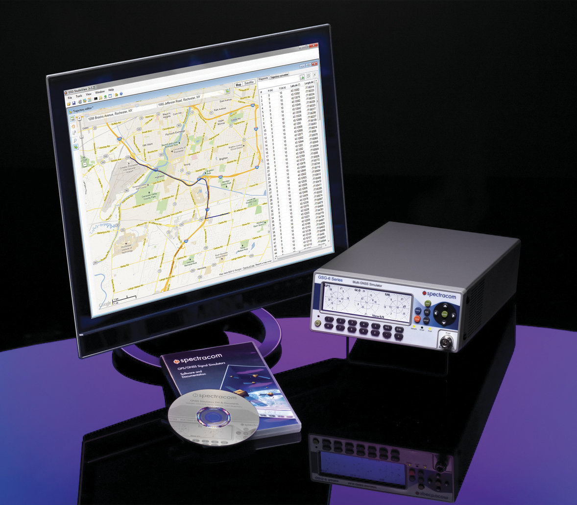
Spectracom’s GSG-6 Simulator with monitor.
In case of a crash, eCall systems automatically call the nearest emergency centre while sending the exact location, dramatically reducing response times. EU member states that do not comply will be refused EC type-approval for new types of motor vehicles.
Spectracom is providing options to ensure that automotive manufacturers who plan to continue selling into this market are equipped with the right tools for testing the eCall regulatory compliance of their equipment.
The Spectracom GSG line of GNSS simulators efficiently simulate all the major GNSS constellations needed for testing compliance of critical signal receiving equipment in a variety of eCall scenarios including:
Positioning accuracy under different conditions
Time-to-first-fix
GNSS receiver sensitivity
Re-acquisition performance following signal outages
Playing specific static and dynamic trajectory scenarios
Changing RF transmit power level manually or remotely sequenced as required by standard
“The eCall regulations require significant effort on the part of the auto industry to comply, and we are pleased to be including standard eCall scenarios as an option for our popular line of Spectracom GSG simulators,” said Lisa Perdue, GSG product manager at Spectracom. “We work in partnership with our automotive industry clients and will continue evolving the simulation product line to meet their needs for compliance testing with life-saving regulations.”
The second set of 10 Iridium NEXT satellites, launched June 25 by SpaceX, are functioning nominally and have begun the testing and validation process.
The batch of 10 satellites was launched from Vandenberg Air Force Base in California, increasing the total number of Iridium NEXT satellites in space to 20.
“We are thrilled with yesterday’s success,” said Scott Smith, chief operating officer at Iridium. “These new satellites are functioning well, and we are pressing forward with the testing process.”
“Since the last launch, the team at our Satellite Network Operations Center has been anxiously awaiting this new batch of satellites. There is a lot of work to do, and we are up for the challenge,” he said.
Now, and for approximately the next 45 days, the newly launched satellites will undergo a series of testing and validation procedures, ensuring they are ready for integration with the operational constellation.
Once testing is completed, Iridium will also hand over control of Aireon’s Automatic Dependent Surveillance-Broadcast hosted payload, to the team at Aireon’s Hosted Payload Operations Center, in Leesburg, Virginia.
The GPS tracking device market is expected to exhibit significant growth potential between 2017 and 2023, according to a new report by Research and Markets.
The key driving factors for the growth of the GPS tracking device market include the increase in sales of commercial vehicles, smaller size, affordable price and high return on investment. Moreover, the advent of cellular technology reduced the service cost, while the decline in GNSS/GPS IC makes inroads in cellphone that provide the scale of economies to GNSS/GPS module supplier.
The report is titled GPS Tracking Device Market by Type, Deployment Type, Industry & Geography – Global Forecast to 2023.
Other findings:
Transportation and logistics to hold the largest share of the overall GPS tracking device market.
APAC will be the fastest-growing market for GPS tracking device during the forecast period.
Septentrio, a designer and manufacturer of GNSS solutions, has awarded the Katholieke Universiteit Leuven (KU Leuven) Ecochallenge team — the winners of the Galileo Masters (Flanders Challenge) of the European Satellite Navigation Competition (ESNC) — with an AsteRx-m UAS receiver for its proposal to use high-precision high-reliability Galileo receivers to modernize inland waterway transport by introducing autonomous technology for the vessels.
The judging panel were impressed with the proposal from the KU Leuven Ecochallenge team to use high-quality Galileo receivers to improve the safety and efficiency on autonomous and existing vessels, which can be retrofitted with the solution.
The ambitious proposal offers a pragmatic step towards rejuvenating inland waterways as a viable ecological alternative for freight transportation, Septentrio said in a news release.
The KU Leuven team also participated in Ecorace Challenge organized by the Flemish Waterways Agency and was both the overall winner in the cargo category as well as being voted the most innovative vessel in 2016.
The AsteRx-m receiver board won by KU Leuven Ecochallenge team is a GNSS solution for applications in autonomous and unmanned vehicles, such as drones. The AsteRx-m UAS offers centimeter-level accuracy at 700 mW using L1/L2 GPS and GLONASS RTK.
The AsteRx-m OEM Board by Septentrio.
“As traffic continues to increase, exploiting inland waterways has been identified as a critical development for easing the pressure on road networks,” said Jan van Hees, director of business development at Septentrio. “High-precision high-reliability positioning technology using GNSS is an essential element of the development. The KU Leuven team have demonstrated an innovative autonomous small vessel prototype already to move cargo safely and efficiently on the Flemish waterways, and we look forward to continued collaboration as they further develop this technology for bigger ships.”
“The team is very pleased with their performance winning the Septentrio Prize and the Ecorace Challenge together in the same year,” said Geert Waeyenbergh of KU Leuven, who mentored the KU Leuven Ecochallenge team. “The received AsteRx-m will further help research and development of better ships going into the future.”
By Gianluca Falco, Gianluca Marucco, Mario Nicola and Marco Pini, Istituto Superiore Mario Boella (ISMB) / Presented at ION ITM, January 2017
The authors of this paper deal with the development of a Robust Position Unit (RPU) based on the real-time implementation of an advanced positioning algorithm. The RPU uses a tightly coupled technique between a mass-market single-frequency GNSS chipset with a low-cost inertial measurement unit (IMU) based on micro-electro-mechanical systems (MEMS) and an odometer.
The tight integration algorithm has been obtained through the design of a complex extended Kalman filter (EKF). Its performance has been verified running the designed real-time algorithm in different challenging environments. One is an urban scenario characterized by narrow streets, few satellites in view and tree-lined avenues. A second harsh environment is represented by a mountain area where the vehicle has driven through long tunnels, overpasses and sharp road bends.
The tests showed how a tight integration algorithm, designed by using raw data from only low-cost sensors, can provide real advantages at a price of careful customizations and adaptations that take into account the particular use and environment.
In the designed tight algorithm, additional features and constraints were added with respect to a common tight strategy in order to provide a navigation solution targeted for land applications. Results show a significant decrement of the positioning errors compared to those obtained with other commercial devices. In particular, the tightly-coupled algorithm provides better estimates of the vehicle position and attitude in case of an urban scenario. The improvement was measured following a standardized testing method, considering the horizontal position error and the yaw angle, as the main performance metrics.
Moreover, the advantages of the embedded system based on an ad-hoc tightly-coupled strategy become even more evident in case of a mountain road that is characterized by frequent tunnels and steep slopes. The experimental results demonstrate the possibility to employ tightly-coupled architectures in low-cost mass-market devices. In the future, the improvement of MEMS technology and the evolution of GNSS, with enhanced signal formats, different frequency bands and more satellites in view, are expected to further increase the positioning performance of mass-marked devices, enabling a variety of new services for road users.
Exploring IMU specifications and correlating them to performance of a final product can be daunting, as differences between MEMS sensors are not always apparent. This article presents achievable performances in fusion technology across a range of IMUs among the best in their respective performance categories.
The number of available options in inertial navigation systems (INS) has grown substantially over the last several years. Major advances have been made not only in inertial measurement unit (IMU) technology, but also in the ability to exploit sensor information to its fullest extent. In both cases, the largest impact can be seen in the micro-electrical-mechanical systems (MEMS) sensors. MEMS sensors are typically much smaller, lower power and less expensive than traditional IMUs. The net result of these improvements is a proliferation of INS systems at much lower cost than were previously available and, therefore, greatly increased accessibility to technology that has historically seen limited deployment. Selecting the appropriate sensor and fusion solution for a particular application can be very challenging due to the large and confusing spectrum of solutions.
The IMUs will be examined in the context of new enhancements to sensor fusion algorithms such as the use of INS profiles. The concept of INS profiles applies environment specific constraints to improve performance in certain types of vehicles, or motion profiles. External sensors such as odometers and dual antenna operation can also aid the solution considerably, but will be unused in this analysis except for occasional comparisons. These external aiding sensors are extremely helpful in many cases and are available to use with a proprietary tightly coupled GNSS+INS solution called SPAN, but this paper seeks to evaluate what performance can be achieved without such aids.
Real-world test results will be examined using a selection of IMUs with the latest SPAN algorithms to illustrate what kind of performance can be achieved with different sensors in difficult conditions. Despite their major advances over the past few years, there are many challenges involved with utilizing MEMS technology to provide a robust navigation solution, particularly during limited GNSS availability or low dynamics. The measurement error characteristics of these devices have improved dramatically, but are still much larger and more difficult to estimate than traditional sensors. Advancements in SPAN sensor fusion algorithms have enabled these smaller sensors to achieve remarkable performance, especially in applications where environmental conditions allow for additional constraints to be applied.
This testing focuses on the land profile, meaning the constraints applied to a fixed-axle vehicle. The test scenarios were selected in such a way as to provide results for ideal, poor and completely denied GNSS coverage.
INS Profiles
GNSS and IMU sensors are only one part of the overall INS system performance. The sensor fusion algorithms used to exploit the available sensor data to its utmost capability are equally as important. In this regard, several improvements have been made to the SPAN INS algorithms to enhance performance under a variety of scenarios.
The largest addition to the SPAN product line is the introduction of INS profiles. That is, environment- and vehicle-specific modeling constraints can be utilized to enhance the filter performance. For example, the land profile, which will be examined in depth in this article, is intended for use with ground vehicles that cannot move laterally. The assumptions introduced for land vehicles, however, are not necessarily valid for different forms of movement, such as those experienced by a helicopter. Therefore, profiles have been implemented via command, and controlled as required by the user, allowing for maximum performance depending on the application at hand.
The land profile is analogous to what has historically been identified as dead reckoning. It is a method that uses a priori knowledge of typical land vehicle motion to help constrain the INS error growth. In other words, it makes assumptions on how land vehicles move to simplify inertial navigation from a six-degree-of-freedom system to something closer to a distance/bearing calculation. The land profile takes the concept of dead reckoning, models it as an update type into the inertial filter and adds a few additional enhancements.
Velocity Constraints / Dead Reckoning. Amongst other optimizations, the land profile enables velocity constraints based on the assumption of acceptable vehicle dynamics. This includes limiting the cross track and vertical velocities of the vehicle. Of all the enhancements, this is the one most colloquially referred to as dead reckoning.
In its simplest form, dead reckoning is the propagation of a position without any external input. In this forum, external input generally refers to GNSS satellites. Without external input, dead reckoning is inherently dependent on assumptions of velocity and heading to propagate the position. These solutions have evolved by integrating inertial and directional sensors to provide more local input and improve the solution propagation. This also is not a perfect method, however, as inertial sensors have their own errors that grow exponentially over time. The land profile velocity constraints explain the bulk of optimizations SPAN has made to enable dead-reckoning performance in extended GNSS outage conditions.
Explaining the velocity updates involves using the current INS attitude (); the vehicle attitude ( ) is estimated by applying the measured or estimated IMU body to vehicle direction cosine ( ). From this, the pitch and azimuth for the vehicle is estimated.Using the magnitude of the measured INS velocity in conjunction with the derived vehicle orientation, the vehicle velocity is computed, allowing the expected vertical velocity and cross-track to be constrained.
A velocity vector update is then applied to the inertial filter to constrain error growth. The effects of this method are expected to be most apparent in extended GNSS outage conditions when the INS solution must propagate with no external update information.
Phase Windup Attitude Updates. Some applications are inherently difficult for inertial sensors due to the fact that these systems are reliant on measuring accelerations and rotations in order to observe IMU errors. When traveling at a constant bearing and speed, separating IMU errors from measurements becomes challenging, so any application that does not provide meaningful dynamics is more demanding on inertial navigation algorithms. This type of condition commonly appears in applications such as machine control, agriculture and mining.
Gravity is a strong and fairly well known acceleration signal, so the real difficulty in this type of environment is managing the attitude, and especially azimuth, errors. Attitude parameters become difficult to observe when the system experiences insignificant rotation rates about its vertical axis.
External inputs can be used for providing input during low dynamic conditions when rotational observations are weaker. These are particularly helpful in constraining angular errors and include the same types used to assist in initial alignment: dual antenna GNSS heading, magnetometers, etc. However, as the goal of this testing is to demonstrate the achievable performance from a single antenna GNSS system, this type of external aid was specifically omitted.
Utilizing a patented technique for determining relative yaw from phase windup, the system is able to distinguish between true system rotation and unmodeled IMU errors during times of limited motion. This is a novel way to extract additional information out of existing sensors rather than adding more equipment and complexity.
The phase windup update is used to constrain azimuth error growth during low dynamic conditions that are typically not favorable to inertial navigation. However, it does require uninterrupted GNSS tracking and is therefore applicable only in GNSS benign environments. This approach is expected to show the greatest benefit in low dynamic conditions and be directly attributable to azimuth accuracy, but only in conditions where GNSS availability is relatively secure.
Equipment and Test Setup
We paired OEM-grade GNSS receiver cards with a selection of IMUs in different performance categories. Since the OEM GNSS platform is capable of tracking all GNSS constellations and frequencies, we configured each receiver to use triple frequency, quad-constellation RTK positioning. The receivers were coupled with a wideband antenna capable of tracking GPS L1/L2/L5, GLONASS L1/L2, BeiDou B1/B2 and Galileo E1/E5b signals.
Three IMUs were tested: an entry-level MEMS IMU (UUT1), a tactical-grade MEMS IMU (UUT2) and a high-performance fiber-optic gyro-based IMU (UUT3).
All GNSS receivers and IMUs were set up in a single test vehicle and collected simultaneously for all scenarios. IMUs were mounted together on a rigid frame, and all receivers ran the same firmware build that were connected to the same antenna.
The tests were conducted using a single GNSS antenna with no additional augmentation sources, such as distance measurement instrument (DMI) or wheel sensor. These are extremely helpful in aiding the solution, but as previously mentioned, this testing seeks to demonstrate the possible performance without the benefit of additional aiding sources. Dependence on aiding sources is a very important distinction when comparing such systems.
The GNSS positioning mode used was RTK via an NTRIP feed from a single base station with baselines between 5–30 kilometers. This was done to try to minimize GNSS positioning differences between the three systems. L-band correction signals were not tracked, and PPP positioning modes were not enabled.
A basic setup diagram of each system under test can be seen in Figure 1.
FIGURE 1. Equipment set-up (not to scale).
Test Scenarios
Four test scenarios will be examined using all the equipment and algorithms described above. They are: urban canyon, low dynamics, parking garage and extended GNSS outage.
The urban canyon test is designed to show the performance of the system in restricted GNSS conditions. The challenge to this scenario is to maintain a high-accuracy solution when GNSS positioning becomes intermittent or even unavailable.
The low dynamics test is intended to illustrate the benefits of the land profile, and specifically the phase windup azimuth updates in maintaining the azimuth accuracy.
The parking garage test will show the efficacy of the velocity constraint models over the different IMU classes as the extended outage provides no external information to the INS filter whatsoever. Again, no other aiding sources were used.
Urban Canyon Test. The urban canyon environment has been and remains one of the strongest arguments in favor of using GNSS/INS fusion in a navigation solution. Because urban canyons are common, densely populated and, of course, a demanding GNSS environment, they represent both an important and challenging location to provide a reliable navigation solution. Typically, they contain major signal obstructions, strong reflectors and complete blockages (depending on the city). For this reason, they provide an excellent use case for INS bridging to maintain stability of the solution.
During most urban canyon environments, it is typically rare to incur total GNSS outages of more than 30 seconds. Therefore, this scenario examines the stability of the solution in continuously degraded, but not generally absent, GNSS. In this case, the coupling technique of the inertial algorithms rather than quality of the IMU dominates achievable position accuracy.
The receiver platform is capable of tracking all GNSS constellations and frequencies. This provides a significant benefit to test scenarios, such as the urban canyon, where the amount of visible sky is significantly restricted. In this case, the more satellites that are observable, the more the tightly coupled architecture can exploit the partial GNSS information.
Though position accuracy between IMUs is less apparent in this condition, attitude results remain separated by IMU quality, which is a major consideration for some mapping applications such as those using lidar or other sensors where a distance/bearing calculation must be done for distant targets.
Test data for this scenario was collected in downtown Calgary, Canada. The trajectory (Figure 2) includes several overhead bridges for brief total outages and some very dense urban conditions.
FIGURE 2. Urban canyon test trajectory.
Table 1 shows the RMS error results of the three systems running both the default and land profiles. The first thing to notice is that the errors are differentiated by IMU category, though the differences are fairly small in the position domain thanks to the tightly coupled architecture. However, because GNSS information is partially available, the differences seen in activating the land profile are fairly modest, especially as the IMU performance rises.
TABLE 1. RTK RMS errors for urban canyon.
As the clearest benefits of the land profile are seen on the entry-level MEMS IMU (UUT1), these will be explored graphically in Figures 3 and 4. Figure 3 shows the position domain, and the RMS differences can be seen in a few cases where the default mode errors increased faster than the land profile. An example of this divergence is most obvious around the 1500-second mark of the test during periods GNSS is most heavily blocked.
FIGURE 3. UUT1 position error (std vs. land). Source: GNSS
FIGURE 4. UUT 1 attitude error (std vs. land). Source: GNSS
Low Dynamics Test. The low dynamics test is designed to emulate conditions experienced by machine control, agriculture and mining applications. In this situation, GNSS availability is generally not the limiting factor and can be used to control the low frequency position and velocity errors of the INS system. The difficulty is managing the attitude, especially azimuth, errors because attitude parameters are very hard to observe without significant rotations or accelerations (Figures 5 and 6).
FIGURE 5. Low dynamics test trajectory. Source: GNSS
FIGURE 6. Low dynamic UUT1 position errors. Source: GNSS
The low dynamics test was collected in an open-sky environment and consisted of traveling in a straight line on a rural road for roughly 2 km at an average speed of 10–15 km/h.
As this type of scenario provides little physical impetus, the azimuth and gyroscope biases are not observable. The reason for this is due to the use of the first-order differential equations to estimate the navigation system errors. Essentially, the differential equations define how the position, velocity and attitude errors change (grow) over time based on each other and the IMU errors. The observability of a particular update is tied to additional states through the off-diagonal elements of the derived transition matrix with the accelerations and rotations experienced by the system.
The overall RMS solution errors for RTK are provided in Table 2. As evident by the results presented, the position and velocity errors are clearly constrained by the continuous RTK-level GNSS position regardless of whether the land profile is enabled or not. The real differentiator in the land profile is the attitude performance due to the use of phase windup as a constraint. Moreover, the attitude improvements are certainly tied to IMU quality.
UUT1 exhibited a noticeable improvement in the attitude performance, while the higher performance IMUs did not. This is not entirely unexpected as the precision of the phase windup is lower than that of the higher grade IMUs.
Looking at the data graphically, Figure 7 shows the effect of land profile on positioning performance in this scenario. The two solutions are indistinguishable on the plot, and are all within standard RTK-level error bounds as was indicated in the RMS table.
Figure 7 shows the attitude accuracy with and without the land profile enabled. Again, the largest gains are seen on the entry-level UUT1, so this is the graphic shown below. This shows how the error peaks of the azimuth estimates are constrained. All the sharp corrections in each plot correspond to the vehicle turning around at the end of each 2-Km line and illustrates how much more powerful a rotation observation can be in azimuth accuracy overall.
FIGURE 7. UUT1 attitude error (std vs. land).
Parking Garage Test. This test was carried out at the Calgary International Airport and was selected to show the INS solution degradation during extended complete GNSS outages. The test consisted of an initialization period in open sky conditions to allow the SPAN filter time to properly converge, followed by a 500-second period within the parking garage. During the interval within the parking garage there were no GNSS measurements available.
Figure 8 provides a trajectory of the test environment. The time spent inside the parking structure is evident on the center bottom of the image.
FIGURE 8. Parking garage test trajectory.
Unlike urban canyon environments that contain partial GNSS information, this exhibits an extended period of complete GNSS outage. During this type of scenario, the IMU specifications become much more significant. IMU errors directly translate to the duration the solution can propagate before the accumulated low-frequency errors of the IMU grow to unacceptable levels. System performance during the outage degrades according to the system errors at the time of the outage and the system noise. The velocity errors increase linearly as a function of attitude and accelerometer bias errors. The attitude errors will increase linearly as a function of the unmodeled gyro bias error. The position error is a quadratic function of accelerometer bias and attitude errors.
Position results from each IMU are shown for UUT 1 in Figure 9. This plot shows the error with the land profile on and off. Without the land profile, the second-order position degradation in an unconstrained system is clearly visible.
FIGURE 9. UUT1 position error (std vs. land ).
By enabling the land profile, the filter constrains IMU errors by utilizing a velocity model for wheeled vehicles. With the constraints, the position errors are startlingly reduced for UUT1 and then progressively less impactful as the IMU quality increases in UUT2 and UUT3, respectively. This makes sense as the IMU error growth is progressively smaller in those IMUs, so the effect of mitigating them is also reduced.
Extended GNSS Outage Test. An extension of the parking garage test is to evaluate the performance in a much longer outage. Instead of 10 minutes, an outage of one hour was tested. Also, due to the extremely long GNSS outage bridging, the effects of adding a DMI sensor (odometer) will also be explored as they are able to be used as a major additional aiding source.
The most common measure of dead-reckoning performance is error over distance traveled (EDT). Due to the very long duration outages in this test, the errors will be reported in error over distance traveled to conform to the typical reporting method. This test was conducted in a mixture of highways and suburban streets with an average speed of 65 Km/h, incorporating a moderate amount of dynamics.
This effect can be seen over the duration of the entire outage as well in Figure 9. In this case, the points are the RMS error over several tests. and the light background shroud represents the one-sigma confidence as time progresses. The confidence increases over time as the overall distance traveled also increases.
FIGURE 10. Land profile EDT with and without DMI aid over 1-hour GNSS outage.
Results and Conclusions
In testing a range of IMUs in some challenging scenarios, this paper has sought to illustrate what kind of performance is achievable using each kind of system. An added complexity is looking at what effect certain inertial constraint algorithms have on this solution.
Although low-cost MEMs IMUs are continuing to greatly improve in quality and stability, the end application is still highly correlated to the overall performance of a selected INS system. For a great many applications, the MEMS devices in combination with a robust inertial filter can meet requirements and provide excellent value. However, some applications continue to require higher end sensors, and possibly post-processing to meet their needs.
The ability of SPAN to utilize partial GNSS measurements such as pseudorange, delta phase and vehicle constraints means even low-cost MEMs are capable of providing a robust solution in challenging GNSS conditions. However, this tightly coupled integration is limited in cases where GNSS is completely denied or when in low dynamic conditions.
INS profiles using velocity constraints, phase windup and robust alignment routines have been shown to provide substantial aid to the INS solution in tough conditions, such as GNSS denied or low dynamics. These improvements were shown to exhibit greater impact as the IMU sensor precision decreases. These abilities, in conjunction with the existing tightly coupled architecture of SPAN and the ever-increasing accuracy of MEMS, IMUs indicate that robust GNSS/INS solutions will continue to proliferate at lower cost targets. However, very precise applications such as mapping will continue to rely on higher quality sensors to meet strict accuracy requirements.
ACKNOWLEDGMENTS
The authors thank Trevor Condon and Patrick Casiano of NovAtel for collecting and helping to process the data presented in this article, and to Sheena Dixon for her tireless editing.
Manufacturers
NovAtel SPAN technology on the NovAtel OEM7 receiver is the testing and development platform for this research. NovAtel OEM7700 GNSS receiver cards and a NovAtel wideband Pinwheel antenna were employed. The inertial units under test were an Epson G320 (low-power, small-size MEMS IMU); Litef μIMU-IC (larger tactical-grade performance IMU still based on MEMS sensors); and a Litef ISA-100C (near navigation-grade IMU using fiber-optic gyros (FOG). Although all are excellent performers in their class and capable of providing a navigation-quality solution, the intent is to show the potential limitations that might arise due to the intended application.
RYAN DIXON is the chief engineer of the SPAN product line at NovAtel Inc., leading a highly skilled team in the development of GNSS augmentation technology. He holds a BSc. in geomatics engineering from the University of Calgary.
MICHAEL BOBYE is a principal geomatics engineer at NovAtel and has participated in a variety of research projects since joining in 1999. Bobye holds a BSC. in geomatics engineering from the University of Calgary.
Taoglas has launched Axiom, a reference design for a low-profile, compact multiple-antenna solution for the next generation of connected cars. Taoglas is a provider of GNSS, automotive and Internet of Things products.
The reference design will help automobile manufacturers overcome one of the biggest challenges of the connected car: where and how to place the multitude of antennas needed for maximum performance.
As many as 18 antennas are needed to power the next-generation connected car, including
multiple cellular antennas for network connectivity;
Wi-Fi for hotspot connectivity;
GNSS for navigation, emergency call systems and other location-based technologies;
satellite radio;
AM/FM antennas;
radar antennas for object detection;
Bluetooth antennas for smartphones and other devices, and
dedicated short-range communications (DSRC) antennas for vehicle-to-vehicle/infrastructure applications.
Locating these antennas in a vehicle in close proximity to each other and additional electronics systems while minimizing interference and maximizing performance is extremely challenging from a design and RF performance perspective.
Manufacturers also need to take into consideration both ease of installation and assembly, and antenna size to determine how they would best work with the vehicle’s aesthetics. Taoglas has worked with the automotive industry for more than a decade, providing antenna solutions to many of the major tier 1 automobile OEMs across the globe.
The Axiom reference design incorporates Taoglas’ wealth of knowledge and expertise gained over the years into a roadmap to help automobile manufacturers more quickly advance antenna configurations that work for their particular make and model.
“Getting that many antennas to work efficiently in a small space at a competitive cost is the number one challenge for the RF teams of automobile manufacturers,” said Dermot O’Shea, co-CEO of Taoglas. “While every car manufacturer will require a slightly different solution, having a multi-antenna reference design to work from allows them to see what they can do in terms of placement and size, and how that impacts performance — all without waiting months for a custom solution to test. They can take the prototype and test it in the field to prove out concepts. Using Taoglas’ Axiom reference design allows them move more quickly to market with solutions that work. We can also work with Tier 1 OEMs to integrate the elements of the Axiom antenna reference design quickly and efficiently directly onto the board of their telematic control units, achieving highest radiated power and sensitivity, while minimizing project time, cost and size, all in one single package.”
Taoglas’ Axiom reference design has integrated nine antennas, including:
LTE Antennas: Four LTE antennas, each operating from 698 MHz to 6 GHz to fully cover LTE worldwide application bands.
Wi-Fi Antennas: Two Wi-Fi elements, supporting both 2.4 GHz and 5.8 GHz bands for Wireless Local Area Network.
GNSS Antenna: An active GNSS element to support GPS, GLONASS and BeiDou navigation systems. L1/L2 options available.
SDARS Antenna: One SDARS element to support satellite radio applications.
DSRC Antenna: One DSRC element, which supports V2V/V2X dedicated short range communication.
Taoglas’ advantage is its ability to integrate all of the antennas required for the connected car in a confined space and maintain maximum performance. The Axiom reference design uses a compact PCB all with SMT-mounted components, and also incorporates a unique board-to-board connector option, allowing the antennas and electronics systems to coexist in a single space inside the vehicle, with no RF cables or additional connectors required.
The Axiom reference design also helps auto manufacturers simplify manufacturing and assembly, with surface-mount solutions that feature the temperature and vibration resistance with the quality standards that manufacturers require. Installation is clipping the PCB into the telematics board.
Telit’s 300-Mbps LE940B6-NA LTE Cat 6 module has received AT&T certification for use on the carrier’s North American LTE wireless networks. The smart module is the first 300 Mbps Cat 6 automotive-grade solution certified by AT&T, Telit announced in a press release.
With advanced security features, the LE940B6 aligns with automakers’ vehicle roadmaps which include requirements for secure, high-speed mobile data that support next generation applications such as advanced diagnostics, infotainment and remote software updates.
“The automotive industry is continuously raising the bar on internet connection speeds to the car,” said Yossi Moscovitz, CEO of Telit Automotive Solutions. “Along with higher speeds, there are increasing requirements for security, quality and environmental performance which Telit has achieved with the LE940B6. With certification of the North American LTE-Advanced LE940B6-NA module variant, auto makers can immediately start delivering car models in the United States with these new modules.”
The LE940B6 powers the entire connected-car platform, supporting current needs while including advanced features that enable future integration of up-coming value-added, telematics and managed services.
The module can run in-vehicle applications inside a secure processing environment from the built-in 64-bit application processor, storage and memory. Automotive application programs can run entirely and securely on the module itself protected by advanced cyber-security capabilities.
Telit has introduced the LE940A9 smart module, an automotive-grade module designed to support LTE Advanced Category 9 (Cat 9) networks.
The series offers three multi-band, multi-mode variants — including voice-over-LTE (VoLTE) — and is optimized for automobile manufacturers to deploy next-generation connected-car technology in world markets.
The LE940A9 is the latest addition to Telit’s xE940 family of automotive-grade modules. According to Telit, it delivers 450 Mbps download and 50 Mbps upload speeds with extremely low latency and advanced security, enabling the next wave of automobile industry’s applications and services which also serve as a springboard for autonomous driving.
https://youtu.be/kXBlY_L3OjI
“Digital transformation is driving the evolution of the connected car with major improvements in driver safety, new revenue streams, and an immersive connected experience,” Telit said in a press release. “With government safety mandates around the globe, added advancements in the connected world, there is greater demand for more value-add services and feature-rich in-vehicle applications.
The xE940A9 40×40 mm LGA form factor nests with the 34x40mm Telit xE920 automotive module family, offering flexibility for the OEM or tier-one integrator.
“From commercial and consumer telematics services, to autonomous driving and driver assistance features, along with a host of other applications dependent on remote software updates, including infotainment; secure, wired broadband-like speed is now a requirement. The evolution to high-speed wireless connectivity is only possible if powered by LTE Advanced, with little to no lag time, for the applications to work.”
The LE940A9 powers the entire connected-car platform, supporting current needs while including advanced features that enable future integration of upcoming value-added, telematics and managed services.
The module can run in-vehicle applications inside a secure processing environment from the built-in application processor, storage and memory. Automotive application programs can run entirely and securely on the module itself, protected by advanced cyber-security capabilities.
“In addition to serving as a significant advancement for the connected car industry, the LE940A9 series is a powerful testament to Telit’s continued technology leadership enabling the future of the connected car worldwide,” said Yossi Moscovitz, CEO of Telit Automotive Solutions. “Not only does the LE940A9 enable unprecedented applications with the speed and low latency of Cat 9 of the multi-mode variants, it also simplifies integration and reduces costs that help accelerate the development of our OEM partners’ global roadmaps.”
The Loran sites at Havre, Montana; George, Washington; and Fallon, Nevada, will continuously broadcast from 0900 (MST) June 20 through 1200 (MST) on June 30. The sites will operate on the 5990 rate but occasionally may operate at other rates.
Only the site at Fallon will operate as an eLoran site. The sites at Havre and George will operate as Loran-C sites synchronized to UTC.
For further information on eLoran, tune into the free webinar on June 15, “Alternative PNT Services.” One of the four presentations will be by Steve Bartlett, executive vice president of UrsaNav, who will provide a brief overview of eLoran technology and performance characteristics with a focus on timing in critical infrastructure applications. Other presentations will cover a new Satellite Time and Location service and indoor timing with a terrestrial beacon system.
UrsaNav is engaged in a Cooperative Research And Development Agreement with the U.S. Department of Homeland Security, the U.S. Coast Guard and Harris Corporation to research, evaluate and document eLoran technology as a candidate for providing position, navigation and timing (PNT) information. eLoran is being evaluated as a potential complementary system to GPS. UrsaNav believes that there is a potentially viable market, in both the public and private domain, for an alternative PNT service that is independent of GPS signal reception or which can be used in GPS-denied environments.
Upgrades to the monitoring stations underpinning Europe’s EGNOS satnav augmentation system will support its evolution, said the European Space Agency.
The current 40 Ranging and Integrity Monitoring Stations (RIMS) sites across Europe and beyond are the bedrock of the European Geostationary Navigation Overlay Service (EGNOS), supplying highly accurate and robust satnav information that can be relied on for safety-critical purposes.
Thales EGNOS V3 RIMS rack.
Once a second, these stations gather raw satnav data to transmit information on signal quality and range measurements to the GPS satellites, allowing EGNOS to identify and remove any error in the signals.
The resulting corrections are then passed to users via a trio of geostationary satellites, delivering a several-fold increase in precision plus “integrity” — a guarantee of navigation service — for safety-of-life applications.
The result is that the EGNOS-augmented signals are guaranteed to meet the extremely high performance standards set out by the International Civil Aviation Organisation standard, adapted for Europe by Eurocontrol, the European Organisation for the Safety of Air Navigation.
The signals from space can therefore be relied on routinely for safety-critical tasks, such as vertically guiding aircraft during landing approaches.
“These current RIMS V2 stations have some inherent limitations, which we’ve sought to tackle in this upgraded V3 design,” said Didier Flament, ESA’s EGNOS programme manager.
Airbus EGNOS V3 RIMS rack.
“For instance, our current stations work only with GPS frequencies L1/L2 P(Y), while the future post-2020 EGNOS system will be operating on a multi-constellation basis, additionally employing modernized GPS signals, notably on both the L2 (L2C) and L5 frequency bands, as well as other signals from Galileo, on the similar E1 and E5 frequency bands.
“Our experience working with RIMS has emphasized the significance on performance of factors such as signal scintillation — caused by the ever-changing ionosphere, the electrically active layer of the upper atmosphere — as well as other environmental threats such as interference and multipath signal reflection.
“So this upgraded design increased robustness to these factors, based on more stringent development and operating standards, along with innovative radio-frequency environment monitoring.
“It also includes upgraded receiver technology to accurately monitor potential GPS and Galileo signal distortion — ‘evil waveform’ signal anomalies — in full compliance with international standards.”
The RIMS V3 stations will be based in the same or similar secure location as today’s stations — typically airports or space-based telecommunication sites.
Dual tracking antenna concept incorporated in EGNOS V3 RIMS design.
The individual RIMS antennas themselves can be relatively compact, about 50 cm high, with links to receiver and computing equipment.
Most of the RIMS V2 station antennas are currently surrounded by dedicated protection structures that limit the impact of interference and multipath local effects.
Analog Devices and Renesas Electronics Corporation are collaborating on a system-level 77/79-GHz radar sensor demonstrator to improve advanced driver assistance systems (ADAS) applications and enable autonomous driving vehicles.
The new demonstrator combines the RH850/V1R-M micro-controller from the Renesas autonomy Platform and ADI’s Drive360 28nm CMOS RF-to-bits technology.
The system-level operation of these two technologies will enable earlier detection of smaller and faster moving objects at greater distances, according to the companies. It will also lower radar system integration efforts and reduce evaluation risks, development cost and time to market for automotive OEMs and Tier One suppliers, the companies said.
Analog Devices Drive360 28nm CMOS RADAR technology platform builds on the company’s established ADAS, MEMS, and radar portfolio to enhance sensor performance for ADAS applications with the world’s first automotive radar technology based on advanced 28nm CMOS with RF performance for target identification and classification. High output power enables greater range and identification of smaller objects, while lowest phase noise enables best unambiguous detection of smaller objects in the presence of large objects.
Renesas offer automotive end-to-end solutions from secure cloud connectivity and sensing to autonomous control. Renesas autonomy Platform is an open platform for ADAS and automated driving, supported by Renesas’ sustainable and scalable SoC and MCU roadmaps. The RH850/V1R-M MCU was specifically designed for use in radr applications.
The Analog Devices Drive360 28nm CMOS RADAR technology platform builds on the company’s established ADAS, MEMS and radar technology portfolio widely used throughout the automotive industry for the past 20 years.
ADI’s high-performance radar solution enables earlier detection of smaller and faster moving objects. High-output power enables greater range and identification of smaller objects, while low phase noise enables unambiguous detection of smaller objects in the presence of large objects. See Analog Devices’ Drive360 video here.
The new Renesas autonomy platform is an open, innovative and trusted platform for ADAS and automated driving, supported by Renesas’ sustainable and scalable SoC and MCU roadmaps, the company said.
The RH850/V1R-M MCU was specifically designed for use in RADAR applications as part of the sustainable and scalable portfolio. The new MCU includes optimized programmable digital signal processing, dual CPU cores each operating at 320 megahertz with high-speed flash of 2 MB and 2 MB internal RAM, while meeting industry temperature requirements.