Category: Defense

  • Anti-jam technology: Demystifying the CRPA

    Controlled reception pattern antennas (CRPAs, pronounced “serpers”), adaptive antennas, null-steering antennas, beamforming antennas…

    You’ve probably heard of at least one of those terms in any discussion around GPS anti-jam technology for defense.

    Because they are all terms that describe essentially the same thing: a specialized antenna that helps protect GPS receivers from interference and jamming.

    But what exactly are they? Where did they come from? How do they work? What comes next? Read on and find out.

    A bit of history

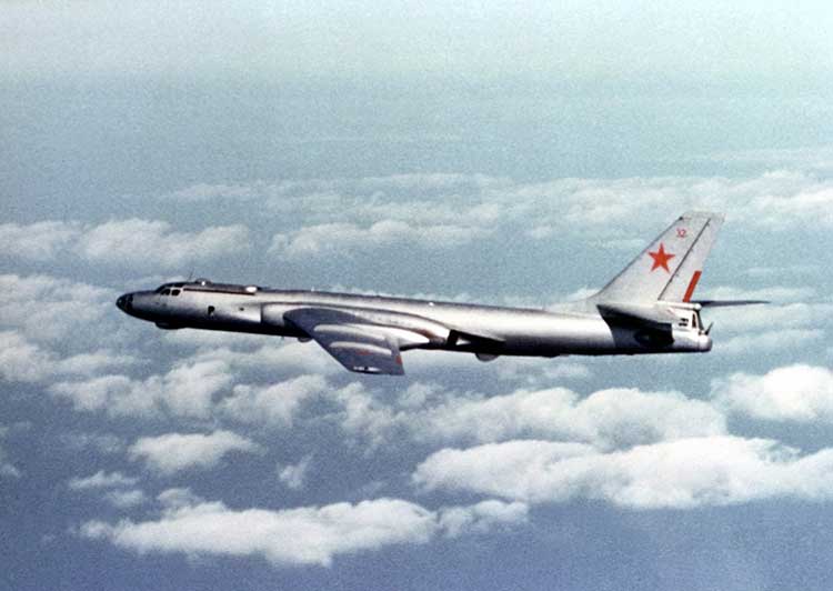
    Let’s go back to the Cold War era, at a time when Soviet and Western states were continuously battling for electronic warfare (EW) superiority. In the early to mid-Cold War, radar jamming was the name of the game. Soviet aircraft, such as the TU-16 Badger and its derivatives, carried a range of EW equipment, including some very high-power jammers designed to interfere with radar systems.

    Figure 1: TU-16 Badger, an important Soviet electronic warfare platform during the Cold War (Photo: Wikipedia)
    Figure 1: TU-16 Badger, an important Soviet electronic warfare platform during the Cold War (Photo: Wikipedia)

    Fast forward to the latter years of the Cold War, and we reach the era when the U.S. was busy developing the exciting new GPS system. The Department of Defense (DoD) wanted to ensure that a robust and accurate global navigation system was available to the military, and so the Navigation System with Timing and Ranging (NAVSTAR) launched its first satellite in 1978, eventually becoming the fully operational GPS system by 1993.

    Magnificent and ground-breaking though it was, it was recognized very early on that GPS relied on very low-power satellite transmissions, and would be vulnerable if someone tried to interfere with it. Given the prevalence of high-power jamming during the still-ongoing Cold War, there was concern that, if an adversary knew about GPS, they could easily render it useless in a given operational area.

    And so it was that the CRPA came to the rescue.

    Enter the CRPA

    Once again, this GPS anti-jam technology finds its roots in the Cold War, and specifically in radar technology, where engineers developed clever ways to ensure their radars could continue to operate in the presence of jamming. Sidelobe cancellation (SLC) was a well-established technique in the radar community, where a received jamming signal could be “cancelled” by combining the outputs of more than one antenna in the right way.

    So, it didn’t take long to adapt this radar anti-jam technology to the problem of GPS protection, and the CRPA was born. At this point I must declare a modicum of national pride, as the earliest operational GPS anti-jam unit that I know of was British. The Plessey PA 9800 GPS Anti Jam Unit was built at Roke Manor in 1984, and tested in the U.S. at the Yuma Proving Ground, Arizona, in 1985.

    This pioneering technology could defeat up to three simultaneous jammers in the shown configuration, but was modular in construction, allowing further channels to be added for handling higher numbers of jammers. And all of this in 1984, in the UK, for a U.S. military navigation system that wasn’t even fully operational yet. Incredible.

    From then until the present day, CRPAs have seen continual interest and development as the technology of choice to protect GPS from jamming. So how do they work?

    Theory of operation

    A CRPA is attractive, because it doesn’t require you to make any changes to the GPS receiver itself: It simply replaces the existing antenna. CRPAs are generally larger than typical GPS antennas, because they contain a number of antenna elements, and some associated electronics to do the clever stuff.

    There’s nothing magical or mystical about the basics of CRPAs: It’s just standard theory from your favorite textbook on adaptive signal processing. But, as ever, the devil is in the detail — how to make them work well in practice is more involved. And as the technology is generally export-controlled, I shall leave out the important in-depth details.

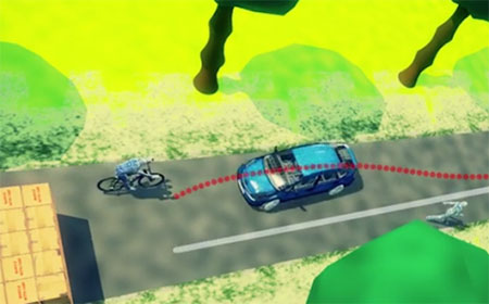
    CRPAs work by exploiting spatial diversity; that is, making use of the fact that the desired satellite signals, and the unwanted jamming signals, generally arrive from different directions. In simple terms, you create a spatial filter, one that removes signals that arrive from particular directions, whilst letting through signals from other directions. To achieve this, rather than use a single antenna, we use an array of antenna elements.

    Let’s think in simple and intuitive terms about how this works. Take a look at Figure 3. Here we have a primary antenna P, and some auxiliary antennas A1, A2, and so on. A signal arriving from the direction shown impinges on antenna A2, and slightly later it arrives at A1, and later still it arrives at P. For the sake of argument, if the signal is a simple sine wave, you will then find that the output from each antenna is that same sine wave, but with a different phase shift depending on the spatial arrangement of the antennas.

    Now, let’s consider what we call the “weights,” which are labeled as w1, w2 and so on. Each of the weights, in this case, is simply a phase shift that we can define. By careful choice of weights, we could choose to make each of the antenna outputs align perfectly in phase, and then, when we sum all the outputs together as shown, we end up with a bigger version of the input signal.

    This is what we would like to achieve if the signal was a satellite. We “steer” maximum overall antenna gain towards that satellite. This is typically what is meant when we refer to “beamforming;” It means steering maximum antenna gain towards a satellite.

    Conversely, we could also choose the weights to have the opposite effect: to minimize or completely cancel out the signal. This, of course, is what we would like to do if the signal was a jammer, and is referred to as “nulling” or “null-steering.”

    Figure 3. Adaptive antenna basics.How do we determine what those weights should be? Well, this is where your standard theory in adaptive signal processing comes in. Let’s say the objective is to minimize the jamming power out of the antenna. We can write the output power of the adaptive antenna as:

    Figure: Michael Jones
    Figure: Michael Jones


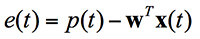
    The average output power can be found by taking expectations:

    Figure: Michael Jones
    Figure: Michael Jones


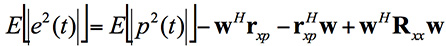
    Taking the minimum and rearranging this leads to the well-known Wiener equation:

    Figure: Michael Jones
    Figure: Michael Jones


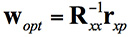
    This Wiener equation is the one to remember. It says that the optimum weights can be found by taking the inverse of the data covariance matrix, and multiplying it by the vector of cross correlations between the primary and auxiliary antennas. As in any adaptive signal processing problem, a simple way to solve the Weiner equation and get the weights might be to use your favorite gradient descent algorithm, such as least mean squares (LMS):

    Figure: Michael Jones
    Figure: Michael Jones


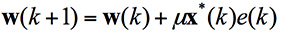
    However, a solution using this approach does have its problems, for reasons beyond the scope of this article. The mathematics of beamforming are also bit more involved, so I’ll leave that out here.

    Rather than the grossly simplified diagram used here, most decent CRPAs also use a more complex architecture based on space-time adaptive processing (STAP) or space-frequency adaptive processing (SFAP). This generally allows much higher levels of jammer cancellation against a wider range of threats.

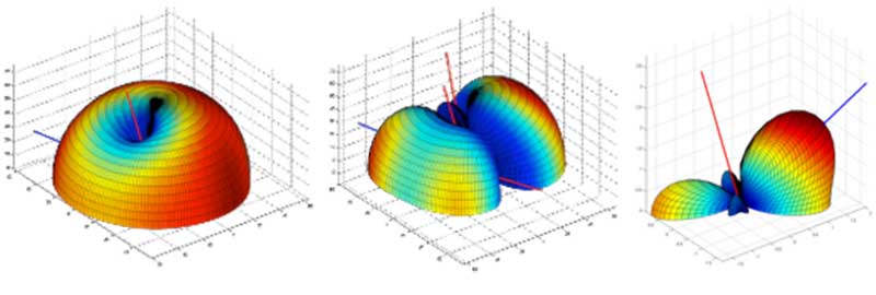
    To finish off this whirlwind section on CRPA basics, let’s see what some example antenna gain patterns might look like. In the figures below, the blue line represents the direction of arrival of a GNSS satellite signal, whilst the red lines indicate the direction of arrival of a jammer. In the first diagram we have a single jamming signal: the antenna gain pattern is a nice hemisphere, as we would generally like, but there is a nice deep null in the direction of the jammer. Moving on to the next diagram, we can see the effect of having three simultaneous jammers on the same CRPA: again we have nice deep nulls in the direction of each jammer, but we are starting to lose more of the sky, and we may start to lose the odd satellite as a consequence. Finally, we have an example of beamforming on a single satellite, whilst nulling out a jamming source.

    Again, it’s beyond the scope of this article, but the layout of the antenna elements plays an enormously important part in the performance and behavior of the CRPA.

    Figure: Michael Jones
    Figure 4. Illustrative beam patterns of a CRPA antenna in the presence of jamming. (Figure: Michael Jones)
    Figure 4: Illustrative beam patterns of a CRPA antenna in the presence of jamming (Figure: Michael Jones)
    Figure 4: Illustrative beam patterns of a CRPA antenna in the presence of jamming (Figure: Michael Jones)

    Operational Anti-Jam Units

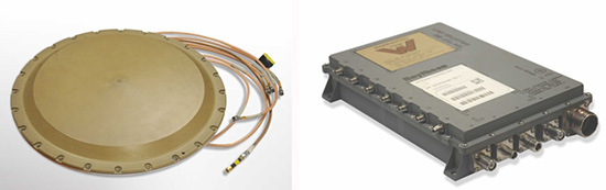
    With some images courtesy of my friends at Raytheon, let’s look at a few examples of deployed military CRPA hardware over the years.

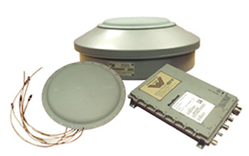
    The GAS-1 system entered service in the U.S. in 1997, as a replacement for the earlier AE-1 (1990 to 1996). The CRPA is composed of two parts: the antenna array, which is a seven-element layout, and the antenna electronics as a separate box. The GAS-1 was incredibly successful and became the de facto standard anti-jam technology, fitted to air and sea platforms around the world. Even today, 20 years after its launch, it continues to be fitted to many platforms.


    Figure 5. GAS-1 CRPA. (Credit: Raytheon)
    Figure 5. GAS-1 CRPA. (Photo: Raytheon)

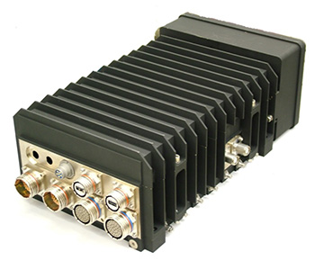
    By the late 1990s and early 2000s, the Navigation Warfare (NAVWAR) program was in full swing, and the military was looking for enhanced protection against evolving jamming threats. The U.S. initiated a program called Advanced Digital Antenna Production (ADAP). The ADAP product, launched in 2006, was a direct form-fit replacement for the analog GAS-1 system, and introduced a number of advanced features. Most notably, the ADAP simultaneously protects both the L1 and L2 frequency bands, and utilizes STAP processing to achieve high levels of wideband jammer cancellation.

    Photo: Raytheon
    Figure 6. ADAP Digital CRPA. (Photo: Raytheon)

    In parallel with the ADAP development, the Digital Antenna Control Unit (DACU) was different in a number of ways. Firstly, it was a true beamforming solution, allowing simultaneous antenna beams to be steered toward satellites, whilst simultaneously nulling out jammers.

    Secondly, it was tightly integrated with the GPS receiver, with the GPS receiver hardware located in the same unit.

    Thirdly, the DACU was able to perform a number of other advanced functions, such as direction-finding of interference sources. Interestingly, the DACU was used to help locate the source of the interference at the notorious Newark airport jamming incident in 2009.

    Figure 7. DACU Beamforming CRPA. (Photo: Raytheon)
    Figure 7. DACU Beamforming CRPA. (Photo: Raytheon)

    By the mid-2000s, CRPA electronics were pretty mature and well-understood. The electronics had been miniaturized, and pretty much everything was put onto a single chip. But the physical size of the antennas persisted as a problem for some platforms requiring low size, weight and power (SWAP).

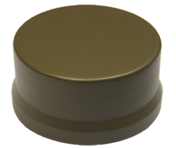
    The Landshield, launched in 2014, was a step-change in CRPA technology. Not just because it was a small and fully self-contained unit (about the size of a hockey puck), but because it was the world’s first CRPA to include true anti-spoofing capability.

    Figure 8. Landshield Advanced CRPA with Anti-Spoof Technology.
    Figure 8. Landshield Advanced CRPA with Anti-Spoof Technology. (Photo: Raytheon)

    Blurring the lines between military and civilian

    Going back a few years, the military was heavily focused on CRPAs and anti-jam techniques in general. Military GPS receivers had been developed and deployed, and the question was how they could retrofit robustness to them. At the same time, the commercial world was heavily focused on mass-market GPS receivers — reducing cost, increasing performance — with little care about jamming.

    If you’d talked to me five or six years ago, I would have said the military sector is 20 years ahead of the commercial sector in anti-jam technology, and the commercial sector is 20 years ahead of the military sector in receiver technology.

    This assertion holds far less true these days; the lines of separation are much more blurred. The military is learning from the commercial world, embracing COTS, and developing new GNSS receivers. Conversely, civilian applications are now much more concerned with jamming, leading to the adoption of low-cost CRPAs in non-military applications.

    The future of the CRPA

    Where will CRPA technology go from here? We’ve already seen that the latest generation of CRPAs now performs anti-spoofing, as well as anti-jamming. But there is plenty more to see yet.

    Although the core technology behind CRPAs is now mature, the trend for the future will be about “doing more with less.” CRPA technology will become more of a multi-function system. Military platforms need to cut down on the number of separate systems they install, and so CRPAs are likely to become multi-functional, performing situational awareness and signals intelligence.

    As antenna technology progresses, we will likely see protected navigation solutions utilizing the same hardware as communication systems and radar systems, providing CESM and RESM functions, and being part of an integrated electronic warfare suite. And conformal antennas will see a resurgence of interest for complex and space-constrained platforms.

    Watch this space.

  • GPS satellite security discussed in House hearing

    A U.S. Congress hearing on March 29 focused on the vulnerability of satellite systems to strategic attacks, according to an article by The Hill. The GPS constellation in particular was discussed as critical to energy, telecommunications and finance sectors.

    Experts and lawmakers expressed their concerns at the joint hearing between the House Homeland Security Committee and House Armed Services Subcommittee on Strategic Forces.

    The Hill quotes William Sheldon, former commander of U.S. Air Force Space Command: “Many of us remember the tagline from the 1979 movie Alien: ‘In space, no one can hear you scream.’ From my perspective, apparently no one can hear you scream about space vulnerabilities either. Many have banged the gong since 2007, but 10 years of studies and policy debates have not produced tangible improvements in our space defense posture. If you know the armed burglar is on the front porch, you do not wait until he’s inside to take action.”

    Retired military officials and a former deputy administrator for the Federal Emergency Management Agency were among those testifying.


  • GPS Source receives security approval for DAGR device

    GPS Source receives security approval for DAGR device

    GPS Source has received Global Positioning Systems Directorate security approval for its family of Selective Availability Anti-spoofing Module (SAASM)-based Host Application Equipment (HAE).

    GPS Source announced security approval for the Enhanced D3 (ED3) and Enhanced FLO-G (E-FLO-G) with integrated SAASM receivers. The ED3 and E-FLO-G are upgradeable versions of the popular DAGR Distributed Device (D3) and are capable of distributing SAASM today, and M-code protected GPS data when implemented.

    Enhanced DAGR Distributed Device by GPS Source.
    Enhanced DAGR Distributed Device by GPS Source.

    GPS Sources’ family of PNT distribution products represents the most advanced, cost effective and comprehensive solution available on the market to support Department of Defense’s GPS modernization efforts. Moreover, the ED3 and the E-FLO-G bridge the gap between legacy systems deployed today and the C4ISR/EW architectures of the future.

    “We understand the importance of designing products that comply with all GPS Directorate security requirements,” said Robert Horton, CEO of GPS Source. “This security approval makes it possible for the ED3 and E-FLO-G to be deployed by military forces without reservation. GPS Source is proud to be a key supplier of such important enablers to the warfighter and to be the provider of innovative military GPS solutions to our defense customers.”

    “Integrating legacy equipment utilizing SAASM receivers with future equipment relying on M-code receivers is challenging,” Horton continued. “But through Independent Research and Development, GPS Source ensured the ED3 and E-FLO-G integrate appropriately with SAASM today and M-code in the future. These accomplishments exemplify the technology in development by GPS Source to sustain the equipment that warfighters will employ today and tomorrow.”

    GPS Source has begun taking orders for the ED3 and GLI-FLO-G. Production will start mid-year. Questions about this technology can be directed to Kurt Williams, director of Sales and Marketing.

  • Spectracom, Satelles sync in multiple indoor locations

    Orolia has synchronized a Spectracom SecureSync high-precision time server with the new Iridium Satelles Satellite Time & Location (STL) time synchronization signal powered by Iridium satellites in several indoor environments in the field. Configured with an embedded STL receiver and a small patch antenna, the SecureSync synchronized with the STL signal in several challenging indoor locations. Indoor success can be attributed in part to use of a low-Earth orbit satellite-based signal 1,000 times stronger than GPS.

    The first successful synchronization was in the interior of a building in one of the most challenging urban canyons on Earth: downtown Manhattan on the 7th floor of the New York Stock Exchange. The second was in the interior of a conference center with multiple sources of potential signal interference during The Institute of Navigation event in Monterey, California. Additional successful indoor timing signal synchronization locations include MiFiD2 events near the Paris Stock Exchange, a multi-story building and inside Gibson Hall in downtown London.

    More GNSS challenged locations to come, the two companies promise.

    Other satellite signals — notably GNSS — have limitations indoors. The Satelles STL signal uses the narrow-band paging channels of Iridium, a one-way transmission from the satellite with a very high gain system. The STL signal is completely different from the wide band, lower gain two-way channel of the Iridium phone. The STL signal is 1,000 times stronger than GPS because it originates from the Iridium constellation of 66 satellites orbiting in a low earth orbit. It is also encrypted for high security, which greatly enhances the resilient PNT capabilities of the Spectracom product lines, specificallly the SecureSync precision time and frequency reference. SecureSync with integrated STL synchronization is available to order from the Spectracom website or by contacting a representative.

    “The new STL signal is the ideal solution for those needing increased security and reliability, applications such as high frequency securities trading, financial transaction time-stamping compliance and critical infrastructure timing,” said John Fischer, vice president of Orolia for advanced R&D. “It is not only an additional signal to back up traditional GNSS, it is also stronger and more secure, adding significantly to the resiliency of high performance systems and networks that must rely on precise time synchronization.”

    Having proven the ability to provide a strong and reliable alternative signal in various indoor field locations, the new globally accessible STL signal adds a significant safety net to any critical GNSS application. Adding to the mix of signals of opportunity the resiliency of positioning and timing for financial, defense and critical infrastructure is greatly enhanced.

    “Orolia is focused on providing Resilient PNT solutions, and by combining and layering technology in innovative ways we help our customers meet their mission goals,” said Rohit Braggs, vice president of Orolia’s PNT networks and sources. “This new satellite-based service provides a unique signal that augments Spectracom systems, enhancing our ability to effectively mitigate emerging GPS and GNSS threats.”

    Orolia is the parent company of Spectracom, McMurdo, Kannad, and Sarbe brands, focused on resilient positioning, navigation and timing (RPNT) solutions that improve the reliability, performance and safety of customers’ critical, remote or high-risk operations.

    Satelles has developed and deployed a real-time PNT service based on low-Earth orbit satellites, the Iridium constellation. Satellite Time and Location (STL) signals are highly secure, penetrate deep indoors, and are available anywhere on Earth.  Satelles partners with other companies to deliver secure time and location capabilities to government and commercial users worldwide.

  • What is the biggest unmanned autonomous vehicle (UAV) challenge?

    What is the biggest challenge facing the UAV industry? Go to gpsworld.com/17marpoll to give us your opinion by March 22 and you’ll also be entered in a drawing to receive a $50 gift card.

    Here are the possibilities on offer, plus an “other” category for you to specify something bigger if you think we’ve omitted anything.

    • Better quality images and video
    • Better, smaller, more lightweight sensors (inertial, Lidar, infrared, spectral, etc.)
    • Integration of other sensors with GPS/GNSS
    • Applications and command-control on mobile devices: smartphones and tablets
    • Virtual and augmented reality
    • Competition from satellite and aircraft imagery/mapping/other
    • Air traffic control and the FAA regulatory environment
    • Other (please specify)

    =

    Watch this space for continuing coverage of developments in UAV navigation and related issues, with in-depth reporting from the upcoming AUVSI Xponential conference in May.

  • Raytheon, US Air Force upgrade navigation in decoy-jammer vehicle

    Raytheon, US Air Force upgrade navigation in decoy-jammer vehicle

    Raytheon Company and the U.S. Air Force validated performance of an upgraded navigation system for the Miniature Air Launched Decoy-Jammer (MALD-J) in six flight tests from B-52 and F-16 aircraft at White Sands Missile Range, New Mexico.

    The system upgrade, designated as GAINS II (GPS-Aided Inertial Navigation System), includes an enhanced multi-element GPS-controlled antenna assembly. The new technology improves MALD-J navigation performance in a GPS jamming environment. Improvements and efficiencies within the design helped to reduce GAINS II unit costs.

    “Improving performance while reducing costs is a win for Raytheon and our customer,” said Brian Burton, director of MALD Programs for Raytheon.

    Raytheon Space and Airborne Systems in El Segundo, California, supported design work for GAINS II, while Raytheon Missile Systems in Tucson, Arizona, supplied systems engineering, integration and testing. Raytheon is now producing and delivering MALD-J systems with the upgraded navigation.

    About MALD and MALD-J

    MALD is a state-of-the-art, low-cost expendable flight vehicle that is modular, air-launched and programmable. It weighs fewer than 300 pounds and has a range of approximately 500 nautical miles. MALD-J adds radar-jamming capability to the basic MALD platform.

    MALD confuses enemy air defenses by duplicating friendly aircraft flight profiles and radar signatures.

    MALD-J maintains all capabilities of MALD and adds jamming capabilities.

  • Homeland Security spells out receiver improvements

    In early January, a new U.S. Department of Homeland Security (DHS) document appeared: “Improving the Operation and Development of Global Positioning System (GPS) Equipment Used by Critical Infrastructure.”

    Improving_the_Operation_and_Development_of_Global_Positioning_System_(GPS)_Equipment_Used_by_Critical_Infrastructure_S508C-coverThe document focuses on receivers used in critical infrastructure, with an emphasis on timing receivers. It provides owners, operators, researchers, designers and manufacturers with information to improve the security and resilience of PNT equipment across the spectrum of equipment development, deployment and use.

    Specifically, its recommendations address:

    • installation and operation strategies that can be implemented for current equipment,
    • strategies that can result in more robust and resilient new and/or improved products based on existing technology and knowledge,
    • research and development that can lead to improved future capabilities.

    It introduces clear definitions of different categories of threats and hazards, including the new term “data spoofing.” It recommends some creative ways to install receive antennas, such as using decoy antennas and obscuring the location of the actual antennas being used, presumably to foil some spoofing attacks. It also points out that modern GNSS receivers are computers, and need to be operated and maintained with good cyber hygiene, just like other computers.

    The extensive list of recommended development strategies will challenge manufacturers while informing purchasers about the features they can seek in new equipment.

    Implementing these recommendations will lead to increased competence — that is, equipment that is better able to accommodate imperfect or faulty inputs, intentional or not.

    The document reflects the recognition that many reported problems or difficulties with GPS could be prevented or mitigated by improvements in GPS user equipment and how it is installed and operated. It is encouraging to see DHS taking steps to remedy this situation, and important that manufacturers of timing receivers, as well as critical infrastructure owners and operators that use timing receivers, follow through on these recommendations.

    The document is posted on the website for DHS’ National Cybersecurity & Communications Integration Center, National Coordinating Center for Communications-Computer Emergency Readiness Team.

  • Name the alt-PNT leader for a $50 gift card

    Quick, what’s the best alternative when GNSS signals are not available? This is not a simple question, but we’re asking for a simple answer. Among the multiple avenues pursued at the U.S. Defense Advanced Research Projects Agency (DARPA), as described in February’s PNT Roundup, which has the most promise?

    • Inertial sensors
    • Chip-scale atomic clocks
    • Cell signals
    • Low-Earth orbit communications satellites
    • Video cameras
    • Ground-based beacons
    • eLoran
    • Other (please specify)

    Go to gpsworld.com/17febpoll to give us your opinion by Feb. 22 and we’ll enter you in a drawing to receive a $50 gift card.

  • ION seeks abstracts for Joint Navigation Conference

    ION seeks abstracts for Joint Navigation Conference

    ion-2017-joint-navigation-conference
    Logo: JNC

    The Institute of Navigation (ION) is seeking abstracts for its Joint Navigation Conference (JNC), which will be held June 5-7 in Dayton, Ohio.

    The abstracts are due Feb. 15.

    According to ION, JNC is the largest U.S. military positioning, navigation and timing (PNT) conference of the year with joint service and government participation. The event will focus on technical advances in PNT, emphasizing joint development, test and support of affordable PNT systems, logistics and integration.

    From an operational perspective, the conference will focus on advances in battlefield applications of GPS; critical strengths and weaknesses of field navigation devices; warfighter PNT requirements and solutions; and navigation warfare.

    The event, which will feature a technical exhibit and showcase of guidance, navigation and control technology products, will include more than 200 operational presentations, ION reports.

    The ION Joint Navigation Conference will take place at the Dayton Convention Center, as well as a classified environment on June 8 at the Air Force Institute of Technology.

  • The changing face of defense PNT

    I have mixed emotions as I write this column. Delighted, absolutely, to be given the opportunity to write for GPS World on topics that I am so passionate about; but also sad that we will not see any more articles from Don Jewell, whose excellent columns I followed so religiously over the years. I never had the opportunity to meet Don personally but, to me, he is irreplaceable. But let’s talk about the changing face of defense positioning, navigation and timing (PNT) — not in the editorial sense, but in the technology sense.

    As we all know, PNT and GPS are no longer synonymous. With a host of innovative technologies on the horizon, PNT is about so much more than GPS these days, and the military knows it. Sure, GPS has been the workhorse of PNT for many years, and it’s not going anywhere anytime soon. I’ll be clear on that: GPS is not going anywhere. But it’s not a complete solution either.

    Let me paraphrase what a friend in the infantry tells me, by saying GPS is a 60 percent solution to their navigation needs. What does that mean? Well, it goes something like this:

    • 60 percent of the time: GPS is great, it does what we need.
    • 20 percent of the time: We are indoors or underground, and GPS is simply not available.
    • 15 percent of the time: We’re in an urban canyon. GPS availability is intermittent, and the accuracy is poor.
    • 4 percent of the time: We’re in forests or dense vegetation, and GPS is sporadic.
    • 1 percent of the time: GPS is jammed.

    You can argue the numbers depending on the mission, but you get the idea. What, then, is the answer for the soldier? Well, first things first: We don’t want to reinvent the good 60 percent so, once again, GPS is here to stay. The question is how do we push past that 60 percent figure and get ourselves closer to 100 percent? Let’s go from the bottom up, and address GPS jamming.

    Overcoming interference

    The classic solution to jamming is an adaptive antenna, also known as a controlled radiation pattern antenna (CRPA). More on this another time but, for now, suffice it to say that CRPAs are a well-understood and mature technology, and can offer very high levels of jamming resistance.

    The often-cited disadvantage of a CRPA antenna is its size, weight and power: As CRPAs employ multiple antenna elements, they are inherently larger and heavier. The electronics can pretty much be covered by a single chip these days, leaving the antennas themselves as the problematic aspect, but advances in antenna technology have also made big hurdles.

    For airborne platforms, conformal antennas designed as part of the structure or fuselage can be used; whilst for the dismounted soldier, the trend is towards wearables, where the antennas may be an inherent part of the clothing or helmet design.

    Aside from adaptive antennas there are a whole host of other techniques in your anti-jam kit bag, including receiver-based techniques.

    It’s a numbers game

    For forests and urban canyons, this is where multi-frequency multi-GNSS comes into its own. It really is a numbers game: The more constellations you use, the more satellites you can choose from, and the greater your chances of seeing enough satellites to derive a reasonable navigation solution. You also have more options for mitigating the effects of multipath and other errors.

    Of course, this gives rise to a potentially difficult question for some governments: In defense applications, do you want to rely on foreign GNSS constellations as part of your PNT solution? The attitude here depends on your own country’s policy and a trade-off of perceived gains against perceived threats. The UK, for example, has chosen to embrace all available constellations and frequencies in future military navigation systems.

    That’s probably about as far as GNSS gets you, because now we’re looking at the 20 percent of the time where the user is indoors or underground. In other words, environments where GNSS simply isn’t available. This 20 percent is perhaps more tricky to address, and is the realm of alternative and complementary PNT technologies.

    Beyond GNSS

    Fusing different sensor modalities to create a combined navigation solution is anything but a new idea. The benefits of combining GPS with an inertial sensor were recognized a long time ago, and this classic pairing continues to be the subject of research today.

    The two technologies are highly complementary in various ways: GNSS offers absolute position, low short-term accuracy, and high long-term accuracy. On the other hand, an inertial sensor offers the opposite: relative position, high short-term accuracy, and low long-term accuracy. It’s a match made in heaven.

    But whilst GNSS plus inertial may be a good choice for, say, airborne platforms, it doesn’t solve the in-building and underground problem. Without GNSS, you need something else.

    Indoor navigation has been one of the hottest research topics of recent times, but there are really two types of indoor scenario: the first is when you’re in a shopping mall or airport. You can use an inertial sensor, Wi-Fi, mobile base stations, and various other bits of infrastructure to help you navigate.

    The second scenario is the military one: You’re in an unfamiliar enemy compound or underground tunnel complex. In this case, there is no GNSS, no Wi-Fi, no mobile communications; and, for navigation, you can only really rely on the sensors you bring with you.

    So what other sensor works underground, and complements inertial?

    Visual/inertial integration

    Visual odometry is an established, yet often overlooked, navigation technology that is undergoing a resurgence of interest, in both military and civilian applications. In simple terms, visual odometry uses sequential camera images to determine motion in a six degrees of freedom reference frame. Using either single or multiple cameras a platform can estimate both its 3D position and orientation, providing much the same information as an inertial sensor — but with a few added benefits.

    Visual/inertial sensing allows 3D reconstruction of a road incident (https://www.youtube.com/watch?v=eBw-DH2p5uo&t=2s)
    Visual/inertial sensing allows 3D reconstruction of a road incident. (Screenshot: Roke)

    Because cameras and associated vision-processing algorithms are capable of detecting corners and features, a 3D model of the environment in which the soldier is operating can also be built up. In other words, we can perform simultaneous localization and mapping (SLAM).

    But like any navigation technology, visual odometry has its limitations. It likes well-defined features in the environment, such as corners, but can get confused by moving objects like trees and clouds. Its performance also depends on factors such as the quality of the camera and lens, and how well the system is calibrated. Like an inertial sensor, it provides a relative positioning solution and is subject to accumulation of errors over time. It’s a great technique, but it really comes into its own when combined with another navigation sensor, such as an inertial unit.

    And it’s not just the military guys who are taking advantage of visual/inertial integration. Just take a look at Google’s Tango project, or what Qualcomm is doing, or Roke’s black box for driverless cars, to name but a few examples.

    Bringing it all together

    Over the course of the last decade or two, the operational landscape for soldiers has changed significantly, with far greater focus on urban warfare. The military realized some years ago that the answer to robust navigation for dismounted soldiers was going to require a range of sensor modalities: no single navigation technology is ideal in all environments. That’s why this has been the focus of so many defense programs of recent years.

    By way of example, the UK Ministry of Defence (MoD) initiated a research program in 2013 called Dismounted Close Combat Sensors (DCCS). The contract addressed a range of soldier capabilities, one of which was the ability to provide reliable soldier position and orientation in all environments.

    The DCCS programme evaluated a whole bunch of technologies, but eventually converged to an integration of three primary sensors: multi-constellation GNSS, a low-cost inertial measurement unit (IMU) and a video camera. The single monocular video camera was used to strap down the IMU, in a very tightly-coupled system. It makes sense: when GNSS is available, use it. When GNSS isn’t available, the integrated visual/inertial navigation sensor continues to provide both location and orientation for the duration of the mission. As it should be for a tightly integrated navigation system, the performance of the combined system outperforms any individual sensor in isolation.

    Whilst integrated sensor systems enable our soldiers to position, orientate and navigate themselves, the performance of individual sensors continues to be pushed to new limits. Inertial technology is advancing all the time, and defense is again pushing the boundaries. Take a look at what DARPA is up to, as an example.

    The missing ‘T’

    Haven’t we missed something? Ah yes, there’s a “T” in PNT. So whilst there would seem to be various options for achieving a robust positioning and navigation solution, we mustn’t forget precise timing for those applications that need it. Quantum technology is flavor of the month here and, once more, the defense agencies are furthering developments: DARPA with its ACES program, and MOD/DSTL via the Quantum Technology Program, to illustrate just a couple of examples.

    So whilst GPS will continue to remain the workhorse, defense PNT is migrating from GPS-only to being a many-faced beast. And I haven’t even gotten started on pseudolites, signals of opportunity, eLoran, and cooperative navigation.

    The future of defense PNT looks pretty good to me.

  • Spirent security experts predict greater risk to GNSS in 2017

    Spirent Communications plc, provider of mobile network, application, services and device-test solutions, is warning of the increased likelihood of disruptions this year to a wide variety of civil and military applications relying on GNSS.

    The prediction of greater risk from hacking and location spoofing attacks by criminal, state-sponsored, and other adversaries is part of Spirent’s annual security forecast for 2017. The forecast also highlights the continued risk of distributed denial of service (DDoS) attacks on Internet of things (IoT) devices and industries, including health care and automotive, that Spirent believes are the prime targets for security threats in the near future.

    In 2016, Spirent’s predictions led off with a prescient warning about the increased risk of cyber espionage, which has since been borne out, most notably by news reports of suspected activities by the Russian government to influence the 2016 U.S. presidential election.

    Also as predicted, in 2016 threats from ransomware, malicious insiders and compromised IoT devices increased, as did attacks on industrial control systems. For example, FBI sources reported on CNN that losses attributed to ransomware in the U.S. were set to exceed $1 billion by the end of 2016. That number is expected to grow in 2017.

    In addition to an increased likelihood of GNSS interference, Spirent’s annual security forecast for 2017 predicts an expansion of risks from:

    • More frequent DDoS attacks against IoT devices, as evidenced in the last quarter of 2016, when multiple major DDoS attacks surfaced worldwide. The most disruptive attack employed Mirai malware covertly installed on a large number of IoT devices. A number of high-profile websites such as Netflix, AirBnB, Twitter, GitHub and others were rendered inaccessible. Spirent believes that perpetrators will continue to innovate and find new methods for improving and broadening these type of attacks.
    • Threats to IoT security, which are increasing as everything that is connected becomes a potential attack vector, including embedded devices, mobile devices, consumer electronics, connected medical devices, industrial control systems, smart home devices, and more.
    • Threats to medical applications, networks, and devices in the health care industry, both the back-office systems on which these facilities run and the medical instruments that provide care to patients. A ransomware infection or data breach could adversely affect patient health and privacy.
    • Threats to connected vehicles by malicious attackers, as a greater number of attack vectors are inadvertently created that enable remotely gaining control of critical operational components of the vehicle, including engine, steering, and braking functions in addition to other vehicle systems that communicate through the relatively insecure CAN bus infrastructure.

    “With the greater drive towards use of autonomous vehicles, which rely heavily on precision GPS positioning and timing, threats posed by signal spoofing, jamming, time tinkering, and more could result in serious disruptions and worse,” said Sameer Dixit, senior director of security consulting at Spirent. “The transportation industry is taking this very seriously and already looking at various ways to protect against these threats. Because of this, we see momentum towards improving GNSS security in 2017.”

    According to an article in Defense One, Timothy Bennett, a science-and-technology program manager at the Department of Homeland Security, has already reported the use of GPS spoofing and jamming equipment by Mexican drug cartels along the border to interfere with the U.S. Customs and Border Protection agency’s use of drones to patrol the area. Unlike the larger drones designed to military specifications, the smaller drones used for this purpose are more vulnerable to these kinds of attacks.

    Spirent’s global network of GPS interference detectors has recorded more than 15,000 interference events since it was deployed in 2015, including a surprisingly high number of unintentional events caused by various forms of interference in the GPS L1 frequency band. A significant number of these unintentional events, which often correlate with transmissions from nearby RF transmitters and telecom equipment, have the potential to interfere with GPS signal reception.

    Dixon noted one bright spot on the horizon: the increasing awareness up and down the technology food chain of the importance of security in these systems, and the entry of large, experienced, and security-conscious players into the IoT arena.

    For information on Spirent’s security solutions, visit https://www.spirent.com/Solutions/Security-Applications.

  • Boeing, US Air Force extend partnership to sustain GPS IIA, IIF

    Boeing and the U.S. Air Force have signed a GPS sustainment agreement to ensure the health of current satellites on orbit. The agreement enables persistent GPS capability for civilians and the military as Boeing works on next-generation GPS satellites.

    Artist's impression of a GPS Block II/IIA satellite in orbit. (Credit: U.S. government)
    Artist’s impression of a GPS Block II/IIA satellite in orbit. (Credit: U.S. government)

    Under the agreement, Boeing will support GPS IIA and IIF satellites on orbit for the next five years. Boeing, which has been the prime GPS contractor for more than 40 years, is now part of the Air Force effort that may lead to the next generation of GPS satellites.

    “This agreement continues Boeing’s strong legacy of GPS innovation and mission support,” said Dan Hart, vice president, Government Satellite Systems. “We are focused on delivering reliable, affordable and resilient GPS capability now and for generations to come.”

    Collectively, Boeing GPS satellites have accrued more than 550 years of on-orbit operation. In March 2016, the company delivered its 50th GPS satellite on orbit to the Air Force and has built more than two-thirds of the GPS satellites that have entered service since 1978.