Tag: 0225

  • The evolution of precise point positioning

    The evolution of precise point positioning

    Essence

    Since the dawn of GPS, researchers have worked to improve the accuracy of estimated positioning, navigation and timing (PNT) from the receiver-derived pseudorange, carrier-phase and Doppler measurements. While the pseudorange-based accuracy of standard point positioning (SPP) at the level of 1s to 10s of meters sufficed for most users, carrier-phase-based relative positioning, real-time kinematic (RTK), network RTK (NRTK) and precise point positioning (PPP) measurement processing techniques were developed to provide decimeter-to-centimeter-level PNT under various constraints. Of these approaches, PPP — generally based on the state-space reduction of measurement errors to a single GNSS receiver from a wide area calibration network — has evolved dramatically. Why should readers read this article, as PPP has been around for some two decades? Well, some communities may consider old performance specifications of conventional/classical PPP, a rather niche technology, for static use with post-processing of measurements, resulting in tens of minutes for solution convergence to the decimeter level. However, there have been many performance advances, with more coming, affecting who uses the technology and how.

    Figure 1: Timeline of PPP evolution.
    Figure 1: Timeline of PPP evolution.

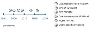
    Figure 1 illustrates the timeline of PPP evolution, from:

    1. The development of the original technique in the late 1990s to reduce static GPS network measurement processing load.
    2. The removal of GPS Selective Availability (SA), simplifying precise satellite clock prediction.
    3. The development of PPP-RTK, in which regional RTK-derived corrections are used to reduce position convergence time and increase accuracy.
    4. Successful isolation of PPP GPS dual-frequency carrier-phase ambiguities to increase accuracy.
    5. Full multi-constellation, multi-frequency (MCMF) processing to greatly reduce position convergence time.
    6. The introduction of GNSS constellation provider corrections. (Individual advances will be discussed in the Elements section.)

    From initial scientific uses to becoming the commercial standard in remote areas or regions with limited GNSS terrestrial infrastructure, these research contributions are leading to ubiquitous open sky decimeter to centimeter-level positioning with a range of available corrections, increasing accuracy and reducing initial convergence for more applications.

    Essentials

    In the late 1990s, to improve positioning accuracy over SPP and avoid the heavy computational burden of network-adjusted relative positioning processing between many receivers, PPP algorithms (detailed in the Elements section) were formulated with undifferenced measurements between tracked satellites and a single receiver (Zumberge et al. 1997). Both pseudorange and carrier-phase measurements are utilized, with the former presenting many decimeter-level references and the latter ambiguous centimeter-level ranging. By filtering continuously tracked measurements over time, decimeter- to centimeter-level positioning is possible, as the state terms, including real-valued estimates of biased carrier-phase ambiguity terms — resulting in tens of minutes to hours of initial convergence time. This approach represents Hatch filtering in the position state rather than the observation domain. Key to PPP is the use of precise satellite orbit and clock estimates derived from a global reference network, which can receive measurements from an entire GNSS constellation. Additionally, to maximize performance, remaining error sources are modeled or estimated. While PPP was initially not as accurate as RTK and, more importantly, took tens of minutes to hours to attain solution convergence, the technique did not have the terrestrial infrastructure constraints of RTK or network RTK, which require reference receivers ~10 km to 15 km and ~75 km away, respectively. Once GPS Selective Availability was turned off in 2000, GPS satellite clock modeling became simpler and more accurate, and scientific and commercial PPP solutions quickly became the standard measurement processing technique for applications requiring decimeter-level accuracy in remote areas or places where it was not economically viable to install (an) RTK base station(s).

    In the 2000s, two different approaches were developed to deal with the shortcomings of PPP: PPP-RTK and PPP-AR. In PPP-RTK, state space corrections from a regional NRTK solution are efficiently transmitted and applied as PPP corrections. As NRTK resolves carrier-phase ambiguities and estimates local atmospheric (ionospheric and tropospheric) refraction and reference station position all in a least-squares sense, PPP-RTK can produce centimeter-level positioning in seconds within a reference station network, where stations can be tens to hundreds of kilometers apart. In PPP-AR, the ionosphere-free linear combination of dual-frequency pseudorange and carrier-phase measurements is not employed; rather, the uncombined version, and the pseudorange and carrier-phase observation models, are extended to include and isolate satellite and receiver fractional carrier-phase biases, allowing PPP ambiguity resolution (AR) to integers with additional satellite code and phase biases from the network solution and between satellite single-differencing. Both approaches are having significant scientific and commercial success.

    Figure 2:  PPP and PPP-AR technology evolution in terms of accuracy versus convergence time.
    Figure 2: PPP and PPP-AR technology evolution in terms of accuracy versus convergence time.

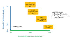
    Unlike RTK, which has the benefit of significant additional calibration information from the reference station, PPP(-AR) must rely only on satellite-based corrections and the strength of the single-receiver observations. In recent years, additional GNSS constellation satellites and frequencies have been brought on-line in large numbers, and GNSS constellation-provided PPP corrections have begun (Xu et al. 2021; Fernandez-Hernandez et al. 2022; Naciri et al. 2023). These developments have greatly increased estimation redundancy, making near-instantaneous PPP without regional reference stations possible (Naciri and Bisnath 2023). This evolution of PPP technology in terms of positional accuracy versus convergence time is illustrated in Figure 2. Therefore, it may be possible to a) dissolve the old GNSS duality of niche, professional-grade versus mass-market, low-cost hardware and software with low-cost hardware utilizing PPP (and RTK and PPP-RTK) software countermeasures to obtain precise PNT; and b) with PPP corrections from GNSS constellations, perhaps, as a reversion to SPP, to have PPP be the natural operational mode of precise GNSS PNT (Bisnath 2020).

    Elements

    Theoretical development

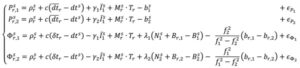
    The PPP measurement processing technique utilizes the GNSS pseudorange (code) and carrier-phase (phase) observables. For receiver r and satellite s, the respective code and phase measurements on frequency can be defined as:

    { P r , i s   = ρ r s + c ( d t r d t s ) + γ i I 1 s + M r s T r + ( b r , i b i s )                                 + ϵ P i Φ r , i s = ρ r s + c ( d t r d t s ) γ i I 1 s + M r s T r + λ i ( N i s + B r , i B i s ) + ϵ Φ i where P r , i s and Φi : pseudorange and carrier-phase measurements, respectively, in meters; ρ: geometric range between receiver and satellite; c: vacuum speed of light; dtr and dts: receiver and satellite clock offset from GPS Time, respectively; γi = ƒ ⁄ ƒ : ratio of frequencies applied to first frequency ionospheric delay I to recover ionospheric delay at frequency i; Tr : zenith troposphere wet delay; M: mapping function to map to satellite-receiver line-of-sight troposphere delay; λi = c ⁄ƒi: signal’s wavelength; N : integer ambiguity on frequency i; br,i and b: receiver and satellite pseudorange hardware biases, respectively; Br,i and B : receiver and satellite phase biases, respectively; and рi and Φi : residual unmodeled errors such as multipath and noise in code and phase measurements, respectively.

    where and Φi : pseudorange and carrier-phase measurements, respectively, in meters; ρ: geometric range between receiver and satellite; c: vacuum speed of light; dtr and dts: receiver and satellite clock offset from GPS Time, respectively; γi = ƒ ⁄ ƒ : ratio of frequencies applied to first frequency ionospheric delay I to recover ionospheric delay at frequency i; Tr : zenith troposphere wet delay; M: mapping function to map to satellite-receiver line-of-sight troposphere delay; λi = c ⁄ƒi: signal’s wavelength; N : integer ambiguity on frequency i; br,i and b: receiver and satellite pseudorange hardware biases, respectively; Br,i and B : receiver and satellite phase biases, respectively; and рi and Φi : residual unmodeled errors such as multipath and noise in code and phase measurements, respectively.

    In order to eliminate ionospheric refraction, the original PPP solution forms the ionosphere-free (IF) linear combination of the dual-frequency GPS code and phase measurements:

    { P r , I F s = f 1 2 P r , 1 s f 2 2 P r , 2 s f 1 2 f 2 2 Φ r , I F s = f 1 2 Φ r , 1 s f 2 2 Φ r , 2 s f 1 2 f 2 2

    From this combined form, the IF float PPP equations are (Kouba and Héroux 2001):

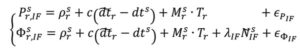
    where the terms with tildes are biased by other terms from the starting observation equations, but allow for enough redundancy for user position, receiver clock offset, a zenith tropospheric term and real-valued, biased phase ambiguity terms to be estimated. In a sequential least-squares or Kalman filter optimal estimation process, positional accuracy depends on the quality of the satellite orbit and clock corrections, along with applying additional error modeling (including satellite and receiver antenna phase center offset and variation, solid Earth tides, ocean loading and phase wind-up), and, most importantly, the quantity, geometrical distribution and quality of the code and phase measurements. The state is initialized with m-level pseudorange measurements and slowly converges to the centimeter-level over tens of minutes to hours as the real-valued, biased phase ambiguity estimates reach steady state. This original or classic PPP solution, characterized by slow convergence to a fixed ambiguity-like positioning solution, may be what some in the community still think of as PPP.

    PPP-RTK was developed as a means to remove these shortcomings of classical, float PPP by supplying PPP-like error state corrections from a regional RTK network to allow near-instantaneous carrier-phase ambiguity resolutionAR, (AR), solving both PPP’s convergence and accuracy problems (Wübbena et al. 2005). Significant operational improvements include increased spacing between (N)RTK reference stations, so less GNSS terrestrial infrastructure is required, and significant reduction in data transmissions from observation space representation (OSR) to state-space representation (SSR). By providing regional atmospheric corrections and ambiguity fixing, RTK-like performance is achieved but with larger CORS spacing. This approach has found commercial success in economically sustainable regions.

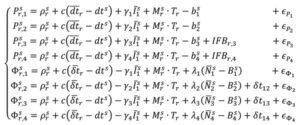
    In parallel, active research continued in PPP-AR, given its desirable characteristic of not requiring regional reference stations. Multiple solutions were developed (e.g., Collins et al. 2008; Ge et al. 2008; Laurichesse et al. 2009), each of which reformulated the PPP observation equations to isolate the phase ambiguities, while overcoming datum defects in the estimation process. For example, the decoupled clock model (DCM) (Collins et al. 2008) isolates the phase ambiguities and directly estimates them as integers. The DCM does not make any assumptions regarding receiver biases and uses separate terms for code and phase clocks due to the imprecision in their synchronization — hence the model’s name. Satellite code and phase biases are required, along with satellite orbit and clock corrections. Then, standard AR methods, such as LAMBDA, can be applied. In the DCM, the fundamental code and phase equations are altered to:

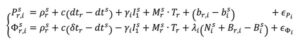
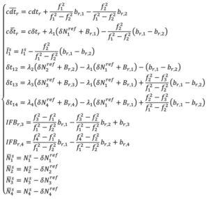
    where dtr, and δtr, are the receiver code and phase clocks, respectively. The receiver pseudorange bias br,i is parameterized in such a way that it is grouped into the receiver pseudorange clock forming dtr and ionospheric delay forming I . These terms are derived to be:

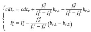
    Through substitution, the DCM dual-frequency observation equations become:

    In decoupling the receiver clocks, the carrier-phase measurements lose their datum. To remove the estimation singularities, one satellite is selected as the reference satellite, its ambiguities are fixed to arbitrary integer values and used for between-satellite single-differencing. N = N + δN , where N are the arbitrarily set integer ambiguities on frequency i and δ N are the differences between the actual integer ambiguities and the arbitrarily set ones. Carrier-phase cycle slips must be detected and changes to the reference satellite accounted for. While initial solution convergence is still a characteristic of uncombined, dual-frequency PPP-AR, the uncombined model solved the problem of brief data outages (solution re-convergence), as the slant ionosphere estimates are used as a bridging parameter between small data gaps.

    The dual-frequency model can be expanded to, e.g., quad-frequencies for multi-constellation, multi-frequency (MCMF) PPP-AR. Accounting for the use of a reference satellite per constellation, accounting for any spatial and temporal reference system differences between constellations, and additional inter-frequency pseudorange biases (IFBs) the up to quad-frequency DCM formulation can be derived as:

    with:

    There is therefore the need for accurate and consistent MCMF satellite orbit, clock, code bias and phase bias corrections. Some constellation-based corrections, e.g., from QZSS, BDS and Galileo, are appearing.

    There is therefore the need for accurate and consistent MCMF satellite orbit, clock, code bias and phase bias corrections. Some constellation-based corrections, e.g., from QZSS, BDS and Galileo, are appearing.

    Results and analysis

    Figure 3: PPP-AR horizontal positioning error for various combinations of GNSS constellations and number of frequencies showing average initial convergence for IGS stations CUSV (Thailand), KIR8 (Sweden) and RABT (Morocco) on day of year 128 in 2024. Results presented are the average of 24 hours of data, reset every three hours.
    Figure 3: PPP-AR horizontal positioning error for various combinations of GNSS constellations and number of frequencies showing average initial convergence for IGS stations CUSV (Thailand), KIR8 (Sweden) and RABT (Morocco) on day of year 128 in 2024. Results presented are the average of 24 hours of data, reset every three hours.

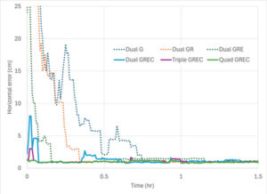
    How has PPP positioning solution convergence and accuracy evolved? The above model is now used to illustrate the performance of MCMF PPP-AR with up to four frequencies. The quad-frequency model has been implemented in the York-PPP client engine developed at York University. For performance illustration purposes, Centre national d’études spatiales (CNES) MCMF correction products are used for consistency and one day (day of year 128 in 2024) of high-quality MCMF GNSS observations are used from each International GNSS Service (IGS) stations CUSV in Bangkok, Thailand, KIR8 in Kiruna, Sweden, and RABT in Rabat, Morocco. Note that data from other days and other comparable stations produce similar positioning results. Simulated real-time, sequential least-squares, kinematic processing was performed for the following observation scenarios: 1) dual-frequency GPS (dual G); 2) dual-frequency GPS and GLONASS (float), with no ambiguity fixing of the frequency-division, multiple access GLONASS signals (dual GR); 3) dual-frequency GPS, GLONASS and Galileo (dual GRE); 4) dual-frequency GPS, GLONASS (float), Galileo and BeiDou (dual GREC); 5) up to triple-frequency GPS, dual-frequency GLONASS (float), triple-frequency Galileo and triple-frequency BeiDou (triple GREC); and 6) up to triple-frequency GPS, dual-frequency GLONASS (float), quadruple-frequency Galileo and quadruple-frequency BeiDou (quad GREC). Operational effects, such as correction latency, are not considered. Figure 3 demonstrates MCMF PPP-AR horizontal error initial solution convergence for these scenarios, averaged from each 24-hour dataset, reset every three hours across the three global stations.

    Figure 4: PPP-AR horizontal positioning convergence times for various combinations of GNSS constellations and number of frequencies to 10 cm and 2.5 cm for data used in Figure 3.
    Figure 4: PPP-AR horizontal positioning convergence times for various combinations of GNSS constellations and number of frequencies to 10 cm and 2.5 cm for data used in Figure 3.

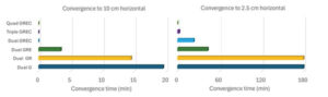
    The dashed time series in figure show the benefits of adding constellations in the PPP-AR processing. From the average of the dual-frequency GPS solutions, the addition of each constellation reduces convergence time by approximately one-half. Then, by adding additional frequencies, convergence time is further reduced to basically instantaneous convergence using available measurements on up to four frequencies from all four GNSS constellations. These results bode well for GNSS data collection in sky-obstructed areas or with lower-quality hardware. Figure 4 provides the convergence times for the average solutions from each processing scenario to reach and sustain below 10 cm and 2.5 cm horizontal error, respectively. These are typical specifications for numerous static and kinematic applications. Four constellation, dual-frequency data are required to attain 10 cm horizontal positioning error or better near-instantaneously. However, to achieve the 2.5 cm convergence definition, at least triple-frequency data are necessary. The post-10 cm convergence horizontal solution accuracy, as defined by rms error, is 9 cm for dual-frequency GPS and 1 cm for each of the GREC processing scenarios. The post-2.5 cm convergence horizontal solution accuracy, as defined by rms error is 17 cm for dual-frequency GPS and 4 cm for each of the GREC processing scenarios.

    Photo:
    Figure 5: MCMF PPP-AR horizontal positioning error for dual-frequency GNSS (left), up to triple-frequency GNSS (center) and up to quadruple-frequency GNSS (right) for IGS stations CUSV (Thailand), KIR8 (Sweden) and RABT (Morocco) on day-of-year 128 in 2024. Results are epoch-by-epoch solutions in the north and east directions in centimeters with 8,640 position estimates in each scenario.

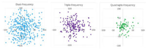
    What if a more robust PPP solution is considered that also further analyzes the introduction of additional frequencies? The same three-station, one-day dataset can be processed in an epoch-by-epoch mode, where all filter states are reset. Therefore, there is no filtering with no assumptions about system dynamics. In this case, using a 30-second sampling rate, results in 8,640 position estimate “snapshots” — a robust process of estimation that can be useful for, e.g., clearly defining integrity for safety-of-life applications. The MCMF PPP-AR results for 1) dual-frequency GPS, GLONASS (float), Galileo and BeiDou (dual GREC); 2) up to triple-frequency GPS, dual-frequency GLONASS (float), triple-frequency Galileo and triple-frequency BeiDou (triple GREC); and 3) up to triple-frequency GPS, dual-frequency GLONASS (float), quadruple-frequency Galileo and quadruple-frequency BeiDou (quad GREC). Figure 5 illustrates the epoch-by-epoch horizontal positioning performance (in cm) for these three scenarios using planimetric subplots. Most position estimates for each scenario are near each subplot center. Adding measurements from the additional frequencies from the dual-frequency base to up to three frequencies and then up to four frequencies for the same four constellations greatly improves horizontal positioning precision and greatly reduces the quantity and magnitude of positioning outliers.

    Table 1: MCMF PPP-AR positioning error for 68th, 95th and 99th percentiles (in cm) for data used in Figure 5.
    Table 1: MCMF PPP-AR positioning error for 68th, 95th and 99th percentiles (in cm) for data used in Figure 5.

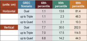
    Table 1 provides the epoch-by-epoch MCMF GNSS PPP-AR horizontal and vertical 68th (1-sigma), 95th (2-sigma) and 99th (3-sigma) percentile positioning error statistics for the same dataset. At the 68th percentile, all scenarios produce centimeter-level horizontal and sub-decimeter-level vertical positioning. However, at the 95th percentile, only triple- and quad-frequency processing can produce centimeter-level positioning in the horizontal component and near decimeter-level positioning in the vertical. To assess extreme position estimate outliers, the 99th percentile statistics show that dm-level horizontal positioning can be maintained with quad-frequency processing.

    Table 2: Average estimation redundancy for data used in Figure 5.:
    Table 2: Average estimation redundancy for data used in Figure 5.

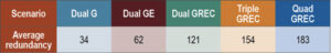
    The MCMF PPP-AR filtered results indicate that near-instantaneous, cm-level PPP is achievable with quality geodetic observations. The epoch-by-epoch, unfiltered results imply that robust, centimeter-level PNT is achievable. Table 2 provides the average redundancy in the epoch-by-epoch processing, where the redundancy is the difference between the number of measurements used and the estimation states. This measure provides insight to how the increase in the number of measurements, while not increasing the number of satellites or the dilution of precision, significantly improves PNT estimation performance for PPP-AR — as this is a measurement-driven technique. The average redundancy increases from 34 to 62 when expanding from dual-frequency GPS to dual-frequency GPS + Galileo and to 121 when using dual-frequency measurements from all constellations. Additionally, increasing processing to include up to triple-frequency measurements and quad-frequency measurements grows this metric to 154 and 183, respectively. The estimation process then becomes more robust against measurement errors and biases. It has more measurement strength to estimate all state parameters, including slant ionosphere refraction terms and integer ambiguities, allowing for improved position estimation precision.

    Evolutionary

    MCMF PPP-AR performance continues to improve. Positioning performance for quality geodetic measurements can produce horizontal centimeter-level positioning performance nearly instantaneously. Robust performance can be obtained with epoch-by-epoch processing, resulting in centimeter-level and few-centimeter-level horizontal and vertical positioning at the 95th percentile level using up to quadruple frequency measurements. Also, inclusion of additional measurements from additional frequencies greatly improves estimation redundancy, thereby improving state estimation.

    Future research developments, testing and implementation include: adding measurements from available fifth frequencies; investigating less reliance on noisy and multipath-prone pseudorange measurements; expanding robust near-instantaneous PPP in urban environments; further defining/characterizing PPP integrity and safety integrity levels; having PPP be an independent or complimentary solution to/with (N)RTK for precise PNT; minimize requirements for atmospheric corrections; further use of PPP in mass-market hardware; and further integration of PPP as part of sensor suite solutions (e.g., automotive, smartphone, UAV, robotics, etc.) for resilient PNT.

    Finally, what is the usefulness of the research in our lives? PPP measurement processing for GNSS is the scientific and industry standard for many user applications. There continues to be growing commercial adoption of this evolving technology, including expanded use in traditional (N)RTK precise applications, mass-market applications using low-cost hardware, and safety-of-life applications, including automotive, other passenger vessels, smartphones, robotics, UAVs and for aids to pedestrians.

  • Seen & Heard: Autonomous sea vessel completes trial, car tracking leads to arrest and more

    Seen & Heard: Autonomous sea vessel completes trial, car tracking leads to arrest and more

    “Seen & Heard” is a monthly feature of GPS World magazine, traveling the world to capture interesting and unusual news stories involving the GNSS/PNT industry.


    Autonomous vessel completes sea trials in Norway

    Photo: Kongsberg Maritime
    Photo: Kongsberg Maritime

    The Reach Remote 1, an uncrewed surface vessel developed by Reach Subsea in partnership with Kongsberg Maritime and Massterly, has been officially delivered after extensive sea trials overseen by Det Norske Veritas and the Norwegian Maritime Authority. This 24 m vessel is equipped with advanced hull-mounted survey sensors and a Work Class Electric ROV, designed to enhance subsea operations by improving efficiency, safety and environmental sustainability.

    ESA in search of very low-Earth orbit technologies

    Photo: VLEO
    Photo: VLEO

    The European Space Agency (ESA) is seeking innovative space application ideas for very low-Earth orbit (VLEO), an orbital region between 100 km and 450 km. This initiative aims to explore new frontiers in space technology by soliciting creative solutions from researchers and innovators. ESA said VLEO presents several advantages, including reduced launch costs, enhanced Earth observation capabilities and a more harmless radiation environment. ESA is particularly interested in proposals addressing technological challenges specific to this orbital regime, such as atmospheric drag mitigation, advanced propulsion techniques and specialized satellite designs.

    Car tracking leads to successful arrest

    Photo: StarChase
    Photo: StarChase

    The Pinole, Calif., Police Department utilized the StarChase GPS-based tracking system to safely apprehend suspects in a stolen vehicle. Instead of engaging in a dangerous high-speed chase, officers launched a GPS-enabled tracker that stuck to the vehicle, offering real-time location tracking. The Pinhole Police Department told The Richmond Standard, “This operation highlights how technology and collaboration keep our community safe — by reducing the dangers of high-speed pursuits while ensuring accountability and swift action.”

    3D mapping of New Zealand coastline

    Photo: nazar_ab / E+ / Getty Images
    Photo: nazar_ab / E+ / Getty Images

    New Zealand has launched a coastal mapping project to help communities understand and mitigate climate change impacts. Led by Toitū Te Whenua Land Information New Zealand, the initiative will use lidar technology to create detailed 3D maps of up to 40% of the country’s coastline throughout three years. The $30.2 million project involves mapping 4,780 square km of coastal and seafloor terrain using specially equipped planes with high-resolution scanning equipment. Two suppliers, Woolpert NZ and NV5 Geospatial, will conduct the mapping across the North and South Islands, beginning in regions such as the Bay of Plenty and Invercargill.

  • Editorial Advisory Board Q&A: The hidden cyber threats to GNSS/PNT systems

    Editorial Advisory Board Q&A: The hidden cyber threats to GNSS/PNT systems

    When we discuss the security of GNSS/PNT systems, we nearly always focus on interference — i.e., meaconing, intrusion, jamming or spoofing. However, GNSS/PNT systems are embedded in systems of systems that also offer many other opportunities for cyberattacks.

    What should we do about it?

    Ellen Hall
    Ellen Hall

    “The key is platform architecture, specifically ensuring robust spatial and temporal partitioning between safety-critical and non-safety-critical functions. Safety-critical functions, such as navigation and autopilot, must be isolated from non-safety-critical functions, such as mission compute, where artificial intelligence typically operates. This partitioning minimizes the scope and effort required to produce design assurance artifacts for airworthiness certification. Additionally, it enhances security by reducing potential attack vectors through the isolation of safety-critical and mission-critical capabilities.”

    — Ellen Hall
    Imminent Federal

    Mitch Narins
    Mitch Narins

    “An old mariner’s proverb is: ‘The prudent mariner never relies solely on any single aid to navigation.’ A more recent statement offers: ‘With so many pieces of sophisticated electronic equipment at our beck and call it would seem some are lulled into complacency and are ignoring basic seamanship.’ In September 2018, the U.S. Naval Institute published an article titled, ‘Professional Mariners Cannot Rely on Electronics Alone.’ The recent news that the U.S. ITAR restrictions on multi-element antenna arrays will be lifted (thanks to many in our community who have lobbied hard for this for many, many years) is excellent news. It will help and was a necessary change — but it is not sufficient. It certainly does not remove the need to pursue complementary, PNT solutions that will ensure the safety, security, and economic well-being of PNT users and their PNT-dependent systems worldwide. From a basic systems engineering perspective, incorporating multiple solutions with independent failure mechanisms is ultimately the end product that we in the PNT community should all be seeking. We must not forget, however, a key element of many of these systems: the human in the loop, who, if continually provided the opportunity to train in PNT-challenged environments, often can be the ultimate system safety element. This will require the design of our PNT services to ensure that the human factors designed into these systems include sufficient information for the human component to understand an off-normal situation and have the training and skills to take the appropriate corrective actions.”

    — Mitch Narins
    Strategic Synergies

  • What’s going on with these UAV sightings?

    What’s going on with these UAV sightings?

    Photo: Jeremy Poland / E+ / Getty Images
    Photo: Jeremy Poland / E+ / Getty Images

    It cannot be denied that people are seeing more objects flying in the night sky. It is suspected that these are unauthorized UAVs collecting information over U.S. and international military bases and, well, also over people looking up at the sky in their backyards at night. It is unlikely that these unidentified flying objects are causing much harm to the civilian population other than being a curiosity. However, it remains unclear what they might be doing over military installations.

    In November and December 2024, numerous reports emerged of UAVs surveilling residential neighborhoods, restricted zones and critical infrastructure across the Northeast United States. This includes areas such as water storage facilities, transmission lines, railway installations, police departments — both local and federal — and military bases.

    Military bases reporting UAV overflights included Wright-Patterson Air Force Base in Ohio, Picatinny Arsenal and Naval Weapons Station in New Jersey and Ramstein Air Base in Germany. In the UK, Royal Air Force (RAF) bases at Lakenheath, Mildenhall, Feltwell and Fairford in the South of England all reported unauthorized UAV overflight activity, which is somewhat concerning for nuclear weapons bases in Europe. Lakenheath appears to have scrambled F-15s to investigate one such UAV incursion.

    Detecting and mitigating threats

    In the United States, the increased intensity of UAV sightings has residents and Congress concerned, while various authorities claim that most of these incidents are harmless. A joint statement by the Department of Homeland Security, the Federal Bureau of Investigation, the Federal Aviation Authority (FAA) and the Department of Defense stated:

    “Having closely examined the technical data and tips from concerned citizens, we assess that the sightings to date include a combination of lawful commercial drones, hobbyist drones, and law enforcement drones, as well as manned fixed-wing aircraft, helicopters, and stars mistakenly reported as drones. We have not identified anything anomalous and do not assess the activity to date to present a national security or public safety risk over the civilian airspace in New Jersey or other states in the Northeast.”

    Nevertheless, these agencies reported, “Local commanders are actively engaged to ensure there are appropriate detection and mitigation measures in place.”

    No other major announcements have followed these incidents, but it would seem logical that military bases have begun activating existing detection and defensive systems. Known countermeasures may include specialized radar, laser, optical, acoustic and radio frequency (RF) detection and defensive systems.

    Radar always has been employed to detect airborne intruders, and the reflections from them appear on a display, which the ground user can then align with a range of potential defenses. However, UAVs are generally small, while conventional radar is designed to pick up hefty reflections from the surface of full-size commercial and military aircraft.

    Photo: Robin Radar Systems
    Photo: Robin Radar Systems

    Robin Radar Systems

    Robin Radar Systems in Holland has worked to refine radar that can detect small flying objects. Birds can cause havoc at airfields where aircraft take off and land at high rates, so detecting birds for airfield operators is one angle for which Robin Radar Systems has developed a reflection capability. A large bird and a UAV might be very similar in size. To differentiate the two, the company found a way to see a Doppler effect (speed differences) within a radar return, which indicates the spinning rotors of a UAV rather than flapping wings — a system they term micro-Doppler radar. This detection system works to find objects many miles away and at well-defined approach angles from the radar antenna. Therefore, these X-Band radars are mostly based at the places you want to protect, such as airfields. Some radars also can be packaged to be transportable, perhaps for military applications, where a temporary base needs to know if enemy attack UAVs might be on their way.

    Other principal detection systems include “sniffing” RF frequencies to detect UAV control signals, but this has a shorter range than radar and does not easily determine distance or approach angle without several triangulating bases. Additionally, of course, UAVs without control signals cannot be detected with this particular RF technology. Optical systems using still/video/infrared (IR) cameras are good in daylight, but not so good in the dark. Acoustic systems use microphones or an array of microphones to listen for rotor sounds but have a shorter range (less than 1/3 of a mile).

    Then, if you have suitable defensive capabilities, you could either take down an unwanted UAV by flying a counter-UAV to collide with and destroy it or by trapping it in a net. In a military situation, many UAVs have been shot down by various types and calibers of guns — and even by very expensive missiles. Electronic defenses include jamming guidance and/or control signals by transmitting signals that overcome and scramble the GNSS and/or control signal or by frying its electronics using high-power microwave transmissions or high-powered laser(s) — these last two systems are expensive and heavy, which makes them cumbersome.

    Spoofing the on-board GNSS receiver by transmitting false satellite signals to steer the UAV away from its target recently has been used by Ukrainian forces to steer attack UAVs back into neighboring countries.

    GNSS jamming is widely used, and there are numerous equipment suppliers; however, spoofing systems are less common due to their additional complexity and cost. Some RF systems can collect data from the opposing UAV and even detect where the operator might be located.

    Of course, not all UAVs straying into restricted airspace come from operators with bad intentions — some might be “Sunday-driver” recreational UAV flyers who have allowed their UAVs to stray into the wrong area. This is another reason the FAA requires formal UAV operator training and certification for commercial operations, but this is not required for recreational UAV flyers.

    DroneHunter drone net capture system. (Photo: Fortem Technologies)
    DroneHunter drone net capture system. (Photo: Fortem Technologies)

    FAA regulations

    The FAA regulations for UAVs are fairly easy to understand, and it would probably take an intentional effort to fly unauthorized into restricted airspace. Otherwise, stay at or below 400 ft, don’t exceed 100 mph, don’t go where you shouldn’t, file a flight plan — ask permission using the automated FAA LAANC online tool — but always stay within visual range of the UAV. Those are most of the basics. Additionally, to operate a UAV commercially, you must also register it with the FAA and install an electronic device to tell everyone in the surrounding airspace the drone’s registration number, which is traceable to the owner/operator. Never fly near clouds, comply with local rules when flying recreationally, and never, ever fly into restricted airspace, particularly around airports, without prior authorization.

    These multiple reported UAV incursions violate FAA regulations, so it is reasonable to assume the operators are deliberately flying illegally. Recreational flying requires the operator to see the UAV at all times — so flying at night is not legal either, as the rules state not to fly an hour after sunset or an hour before sunrise. Operators in restricted airspace are committing a crime punishable by fines and/or years in prison. Yet they still fly, so are they nuisance operators who don’t care or is the activity criminally motivated or orchestrated offshore?

    Utilizing UTM

    Would the coming unmanned aircraft system traffic management (UTM) have been able to keep these intruders away? I am not sure, but UTM is designed to manage UAV traffic, so presumably, it could manage these UAVs to comply with traffic requirements. However, these intruders are already ignoring existing laws, so UTM may more readily enable the identification of rogue UAVs and operators. Recent tests at the FAA/NASA UTM test range in North Texas have drawn huge interest from Walmart and Amazon, as they push to get UAV package delivery working. Wing now delivers for Walmart using a production UTM system in Dallas and Fort Worth, Texas.

    To wrap this up, amongst many recently reported unidentified flying objects, several have been identified as probable UAVs, and some of those over restricted areas could be detected and managed with existing technologies. FAA regulations ban flights in restricted airspace unless approved — i.e., working in coordination with those ground facilities. There are UTMs for UAVs already being used commercially, which could assist in managing all UAVs.

  • How machine control helps level, cut and dig in diverse environments

    How machine control helps level, cut and dig in diverse environments

    Photo: Leica Geosystems
    Photo: Leica Geosystems

    Machine control systems, which combine positioning sensors — both GNSS receivers and inertial systems — with computer displays, give operators better insight into and control over their work. Whether moving dirt on a construction site, spraying crops on a large farm, or moving cargo containers in a port, machine control increases efficiency and precision while decreasing accidents and fuel consumption.

    Machine control systems enable operators to accurately position buckets, blades and other implements on their machines without having to first survey and stake the work site, or having to constantly check their work. They give operators a clear reference between the position of the machine bucket or blade and the design surface, thereby increasing their productivity and accuracy. They also utilize labor and equipment efficiently to reduce costs and minimize wear-and-tear. Finally, by collecting data during their operations, they help teams communicate better and share models.

    Machine control, which first began to be implemented in the 1990s, is being increasingly adopted across a variety of different types of construction equipment — including graders, dozers, and, more recently, excavators. Now, beyond simply providing operators with a visual guide to the position of their buckets or blades, automated machine control moves the blade to grade by talking directly to the machine’s hydraulics, enabling new or less-skilled operators to perform like long-time professionals and increasing the speed and precision of even the most experienced operators.

    The three case studies in this cover story highlight the need for precision control of the implements on earth-moving machines, the importance of good data and the need to make the process as easy as possible for the operator.

    ComNav Technology

    Enhancing construction projects in the Maldives

    The Maldives consists of numerous coral reef islands with low soil-bearing capacity. Using heavy machinery in such an environment requires careful management of movement and precise operations while avoiding damage to local coral reef ecosystems, thus preserving marine life and the natural landscape of the islands.

    using heavy machinery among sensitive coral reefs requires careful movement and precise operations to avoid damaging them. Photo: ComNav
    using heavy machinery among sensitive coral reefs requires careful movement and precise operations to avoid damaging them. Photo: ComNav

    As an advanced construction solution, ComNav Technology’s XE100 Guidance System for Excavator employs high-precision GNSS positioning and heading technology coupled with inertial sensors. In construction projects in the Maldives, the XE100 not only provides precise guidance for operators on land but also enables efficient and precise underwater operations in complex marine environments while minimizing ecological impact. Its excellent performance has brought significant benefits to construction projects in the Maldives.

    The Maldives’ construction environment is complex and variable, requiring precise equipment to adapt to diverse terrain. The XE100 supports multi-constellation multi-frequency GNSS, delivering centimeter-level accuracy. This ensures that, whether for leveling, slope cutting, or digging, the system delivers precise instructions for bucket operations and guarantees accurate excavator positioning, even in challenging conditions.

    ComNav technology’s Xe100 GNSS machine control system delivers centimeter-level accuracy in complex and variable environments. Photo: ComNav
    ComNav technology’s Xe100 GNSS machine control system delivers centimeter-level accuracy in complex and variable environments. Photo: ComNav

    For scenarios requiring underwater operations or mixed land and water tasks, the XE100 overcomes the traditional challenge of locating exact coordinates. The GNSS tablet’s intuitive display of coordinate points helps operators identify work areas and select appropriate excavation actions. This ensures safety, reduces technical barriers, minimizes the need for rework, and significantly enhances construction quality while maintaining high efficiency and precision.

    Construction projects in the Maldives often face challenges such as high humidity, high salinity and frequent vibrations. Each component of the XE100 is designed to withstand harsh environments with excellent durability. The system’s modular design also supports expansion to other construction machinery, enhancing flexibility and paving the way for future technological upgrades.

    As a nation abundant in marine resources and dependent on tourism, ongoing infrastructure development and maintenance are critical to the Maldives’ economy. The XE100 system improves construction accuracy, reduces operation time, ensures safety, and lowers costs, thereby accelerating project timelines.

    Leica Geosystems

    Machine control and automation for snow management

    The allure of pristine slopes and perfectly crafted terrain parks has always drawn adventurers to the mountains, but the landscape of snow management is shifting dramatically. With rising temperatures and unpredictable weather patterns, climate change poses a significant challenge to the snow sports industry. Natural snowfall is becoming less reliable, leaving resorts dependent on costly snowmaking systems that strain resources and budgets.

    Leica alpine office enables resorts to achieve operational goals while safeguarding the environment by precisely managing snow management and reducing waste. Photo: Leica Geosystems
    Leica Alpine Office enables resorts to achieve operational goals while safeguarding the environment by precisely managing snow management and reducing waste. Photo: Leica Geosystems

    For snowparks, these challenges are even more acute. Crafting intricate features such as halfpipes, jumps and rails requires precision and significant amounts of snow — an increasingly scarce resource. Amid these difficulties, the need for sustainability has never been more pressing.

    The tech that’s changing the game

    Leica Geosystems’ snow management solution, the Leica iCON alpine, paired with Prinoth snow groomers, is helping resorts get more out of less, making the construction of snowparks more efficient and sustainable.

    The Leica iCON alpine system leverages GNSS and advanced inclination sensors and inertial measurement units (IMUs) to measure and manage snow depth accurately. Mounted on any snow groomer, this system continuously collects data, ensuring that operators can see the exact snow depth beneath the blade and tracks — accurate to within ±3 cm. In other words, it’s like X-ray vision for your snowcat.

    the leica icon alpine, paired with Prinoth snow groomers, is helping to make the construction of snowparks more efficient and sustainable. Photo: Leica Geosystems
    The Leica Icon Alpine, paired with Prinoth snow groomers, is helping to make the construction of snowparks more efficient and sustainable. Photo: Leica Geosystems

    Need a perfect jump? Create a 3D model and import the data, which can be read on the screen inside the groomer’s cab. It even handles tricky terrain with features like avoidance zones and anchor point searches. This setup doesn’t just make slopes look good; it helps operators work smarter, not harder.

    Snow measurement for World Cup Slalom course

    For the past two years, Killington Mountain Resort in Vermont has been utilizing the Prinoth Connect Snow Measurement system powered by the Leica MC1 software.

    Killington is one of the first resorts in North America to invest in snow measurement, and it has been vital to executing the Women’s Slalom and Giant Slalom World Cup builds in 2023 and 2024. Killington has the snowmaking capability to cover the race trail, Superstar, with snow in about 100 hours. With the software, the teams can read the snow depth to +/- 3 cm, using snow measurement sensors instead of long metal probes. The software helps increase the efficiency of both snowmaking and grooming, making the build easier for the grooming operators, more straightforward for officials, and safer for the racers.

    Leica’s machine control solution has been vital to precisely executing the Women’s Slalom and Giant Slalom World Cup builds. Photo: Leica Geosystems
    Leica’s machine control solution has been vital to precisely executing the Women’s Slalom and Giant Slalom World Cup builds. Photo: Leica Geosystems

    From the snow to the dirt

    However, Leica Geosystems machine control technology is a year-round solution thanks to its versatile Leica MC1 platform, which allows the same hardware used for snow grooming to seamlessly transition into off-season applications such as summer earthworks, trail construction and road maintenance. With a single investment, resorts get a multipurpose tool that eliminates the need for separate systems, cutting costs and complexity.

    For instance, in the summer months at the Rieberalp in Davos Rinerhorn, the Leica MC1 solution powers excavation work for projects such as creating a reservoir and ensuring precise and efficient earthmoving. In the winter, the same system transitions to snow groomers, optimizing snow management on the slopes. This effortless switch between applications highlights the adaptability and value of the Leica MC1 platform, enabling ski resorts to get the maximum out of their investment while maintaining top performance year-round.

    Technology for more sustainable snowparks

    With precision snow management and reduced waste, resorts can achieve operational goals while safeguarding the environment. Adopting digital solutions such as these ensures that ski resorts and snowparks can continue to deliver world-class experiences for generations to come.

    Trimble

    Across digital dimensions on Te Ara Tupua

    Te Ara Tupua is an initiative by the New Zealand Transport Agency aimed at enhancing transport resilience while establishing a walking and cycling route between Wellington and Lower Hutt. The Te Ara Tupua Alliance includes the NZ Transport Agency and its design and construction partners: Downer NZ, HEB Construction and Tonkin + Taylor. To execute this project, the NZ Transport Agency is collaborating with Taranaki Whānui ki te Upoko o te Ika and Ngāti Toa Rangatira as iwi mana whenua. This collaboration inspired the name Te Ara Tupua, referencing the Māori creation story in which Ngake and Whātaitai, two tupua (ancient beings), formed Te Whanganui-a-Tara (Wellington harbor).

    The Ngā Ūranga ki Pito-One section of Te Ara Tupua will be built on the harbor’s edge, from Ngā Ūranga Interchange to Honiara Te Puni Reserve in Pito-One and connect with the new Pito-One to Melling section. The project will deliver a new resilient coastal edge protecting the road and rail while providing transport options and a safe route for walking and cycling between the two cities.

    The solutions involved include:

    • Trimble Marine Construction System
    • Trimble SketchUp
    • Trimble Stratus Software

    The benefits of the project include:

    • Reduced project timeline.
    • Improved safety for construction crews and the public.
    • Increased productivity.
    • Higher precision placement of embankment blocks.
    • Reduced environmental impact.
    • Real-time progress visibility for stakeholders.

    Te Ara Tupua will deliver a new resilient coastal edge protecting the road and rail while providing new and safer transport options. Photo: Trimble
    Te Ara Tupua will deliver a new resilient coastal edge protecting the road and rail while providing new and safer transport options. Photo: Trimble

    Te Ara Tupua is currently under construction along the western coastline of Te Whanganui-a-Tara with the aim of being completed in 2026. The Pito-One to Melling section of Te Ara Tupua is the first completed section of the project and was delivered by the contractors, Fulton Hogan.

    The Pito-One to Melling section is a 3 km separated cycling route stretching from Pito-One to the Hutt River Trail near Bridge Street. The new path eventually will join the Ngā Ūranga to Pito-One section of Te Ara Tupua, which connects to the Hutt Road and Thorndon Quay.

    The construction of Ngā Ūranga to Pito-One section of Te Ara Tupua includes a 4.5 km shared path, shared path bridge, rock revetments, seawalls and landings. To protect the shared path, road and rail line against wave action, erosion and sea-level rise, an essential part of the new pathway is the construction of embankments (or revetments).

    Underwater resilience

    Te Ara Tupua is the first project where seismic performance has been considered and tested in the design elements, including the new seawall built over a large active faultline.

    Two main types of material are required for this project. Rock is being used for the revetment (the sloping rock seawall), which will protect the reclamation and the path from the sea while the remaining material is general fill. These are being sourced in Taranaki and Golden Bay with rock from Golden Bay being transported by barge, greatly reducing the number of truck movements.

    XBlocPlus units are a unique cost-effective solution for Te Ara Tupua. These blocks are poured in the shape of an ‘X,’ which interlock and stack on top of each other to create a seawall with a steeper incline.

    Using these interlocking concrete blocks reduces the seawall’s physical footprint and impact on the marine environment, enabling the project to use less material at a lower cost compared to a rock revetment.

    Through this innovation, the project team of engineers and ecologists (Te Ātiawa, Ngāti Maniapoto, Ngāti Tūwharetoa and Ngāti Apa) worked alongside lead cultural designer, Len Hetet to combine cultural and environmental design, which resulted in Te Ripowai, the unique Te Ara Tupua ecological XblocPlus unit. Te Ripowai speaks of the rippling water and connects to a Te Ātiawa whakatauki of guardianship. The guardians must keep the ripples occurring, else water becomes still and life will cease to exist. Te Riopowai includes surface patterns and textures to encourage growth of marine plants.

    The Ngā Ūranga to Pito-One pathway shoreline ultimately will have 6,663 of these blocks of varying shapes.

    operators of excavators with grapple attachments needed to move eight different block shapes into place with an 80 mm tolerance. Photo: Trimble
    operators of excavators with grapple attachments needed to move eight different block shapes into place with an 80 mm tolerance. Photo: Trimble

    Block placement

    Placing these blocks with precision and speed initially created some concern for the project team. Operators in excavators equipped with grapple attachments needed to move the units into place, initially about 4 m underwater, to a tolerance of about 80 mm to assure embankment strength. To further complicate the construction, there are eight different block shapes.

    It’s a task purpose-built for real-time digital twins and machine guidance, according to the Alliance. With help from SITECH, the survey team looked to its digital assets.

    First, Jan du Preez, survey manager with the Te Ara Tupua Alliance, relied on Trimble SketchUp to accurately model the individual blocks. Then, the team combined the Trimble Marine Construction (TMC) System with a digital model of the excavator. Laser scans along the shoreline provided a digital record of the existing conditions. Even the sequential placement of the blocks is planned in the digital space.

    On the job, an operator selects a designated block for placement on the screen, then uses the excavator grapple attachment to pick it up. TMC provides real-time feedback on the block’s position, rotation and tilt as the operator navigates to the appropriate position, even underwater.

    Du Preez added, “With TMC, the operators can ‘see’ where they are placing them under the water. Because they’re working in an active tidal area with most of the blocks sitting underwater, the idea was to make the process as easy as possible for the operator with highly visual markers on the screen. Every step is color coded, which allows operators to just focus on the colors, rather than trying to see underwater with the naked eye.”

    As the block is placed within the 80 mm tolerance required to interlock with the blocks above, the operator records the as-built position, and the screen shows green. The operator then releases the grapple and moves on to the next block.

    When asked about efficiency, du Preez noted, “The initial program specified placing 15 blocks per day. We are currently placing between 35 to 45 blocks per day depending on site conditions. We estimate that we’re seeing about three times the productivity compared with more conventional methodology — though I’m still not sure how we would have done this without TMC. We would have had to come up with some kind of visual marker and then perform quality checks with divers. It would have been time consuming and very costly.”

    Shared progress

    The benefits of the digital workflows to stakeholders, according to du Preez, are many, with transparency being the overarching benefit.

    Unlike a traditional contract where owner and project team are separate, in an alliance model the client is an integral part of the team. That said, while NZ Transport Agency, Waka Kotahi, et al., are involved in the everyday running of the project as part of the alliance, they also have a board. “Every time the Alliance board of directors sees our solution, they are completely blown away by what we’ve been doing and how we’re doing it,” du Preez said. They particularly like the regular drone flights that capture progress updates.

    “All survey data, models and regular flight imagery are loaded and stored in Trimble Stratus for sharing so that stakeholders always see the latest project status. The entire Alliance really appreciates this level of real-time digital visibility into the project.”

    Ngā Ūranga ki Pito-One is on track for completion in 2026. When complete, the Te Ara Tupua will deliver a safe, connected and resilient route, enabling more people to walk or bike, and connect with local paths in both Wellington and the Hutt Valley.

  • First Fix: Freeing CRPAs

    First Fix: Freeing CRPAs

    Figure 4: Illustrative beam patterns of a CRPA antenna in the presence of jamming (Figure: Michael Jones)
    Illustrative beam patterns of a CRPA antenna in the presence of jamming (Figure: Michael Jones)

    Controlled Reception Pattern Antennas (CRPAs, pronounced “serpers”) are still the single most effective counter to the threat to GNSS from jamming and spoofing — a growing problem in and near conflict areas, such as Ukraine and the Middle East. CRPAs, which make use of the fact that the desired satellite signals and the unwanted jamming signals generally arrive from different directions, reduce the effective range of jammers by up to five orders of magnitude. They are attractive because they replace existing antennas on GNSS receivers without requiring any other changes — though they are generally larger than typical GPS antennas because they contain several antenna elements and some associated electronics.

    Beginning on Sept. 15, 2025, CRPAs will no longer be covered by the International Traffic in Arms Regulations (ITAR), which prohibit the sale outside of the United States of defense articles, services and technical data and impose very large penalties for violators. ITAR is managed by the Directorate of Defense Trade Controls (DDTC) in the Bureau of Political-Military Affairs at the U.S. Department of State, which announced the rule change in mid-January. It removes items that “no longer warrant inclusion” from the U.S. Munitions List (USML), which defines the “defense articles” that fall under ITAR jurisdiction. CRPAs for PNT will instead be classified as dual-use commercial items and fall under the Export Administration Regulations list managed by the Department of Commerce. The Directorate removed CRPAs for PNT from the USML because they “no longer provide a critical military advantage, with increasing commercial utilization applicable to civil GPS resiliency” and because the department “intends to facilitate civil global navigation system resiliency.”

    This is a seismic shift that many in the GNSS/PNT community — including the National Space-Based Positioning, Navigation and Timing Advisory Board (PNTAB) — have been advocating for years. While U.S. manufacturers have been prohibited from exporting CRPAs, TUALCOM, a Turkish company based in Ankara, has been selling 4- and 8-element CRPAs for GNSS applications, as have some Canadian companies.

    Airlines and manufacturers of autonomous vehicles will be among the early beneficiaries of this policy change, as will many safety-of-life applications. Presumably, the vast expansion in the market for CRPAs also will quickly lead to a sharp drop in their cost.

    In a November 2022 presentation to the PNTAB, Brad Parkinson listed the use of CRPAs among the major techniques that can make GPS receivers “virtually immune” to jamming and spoofing, recalling that they were first tested in 1978. However, he pointed out, they had been neglected because they were perceived as too expensive and large for many applications, because of delays in implementing the L5 signal, and because ITAR prohibited beam-steering antennas with more than three elements. He argued that restrictions on GNSS CRPAs were no longer effective at preventing potential enemies of the United States from using them.

    Barring a reversal from the new administration, U.S. CRPA manufacturers can now help protect GNSS worldwide from jamming and spoofing.