Quanergy Systems, a provider of lidar sensors and smart sensing solutions, is offering a new sensor.
Quanergy’s S3 lidar sensor
The S3-Qi is a miniature solid-state lidar sensor that is 15 percent the size of the previous solid-state model, the S3. Quanergy is displaying the new sensor along with its other products in Booth 767 at AUVSI’s Xponential May 3-5 in New Orleans.
The S3-Qi, offered four months after the original S3, has a smaller 1 inch by 1.5-inch footprint, weighs about 100 grams and has low power consumption. The small form factor, combined with a cost-effective design, makes the S3-Qi well suited for applications such as drones, intelligent robotics, security, smart homes and industrial automation.
Mass production of the S3-Qi is targeted for the first quarter of 2017.
“We are excited to raise the bar, once again, with the expansion of our product portfolio,” said Louay Eldada, Quanergy CEO. “We continue to push the boundaries on behalf of our customers. The S3-Qi is a testament to our focus on the user and our investment in innovation for game-changing smart sensing solutions offered at price points that make their use ubiquitous. In drones, payload and battery runtime benefit greatly from our compact sensors.”
Quanergy’s lidar sensors have applications in more than 30 market verticals including security, transportation, terrestrial and aerial mapping, and industrial automation.
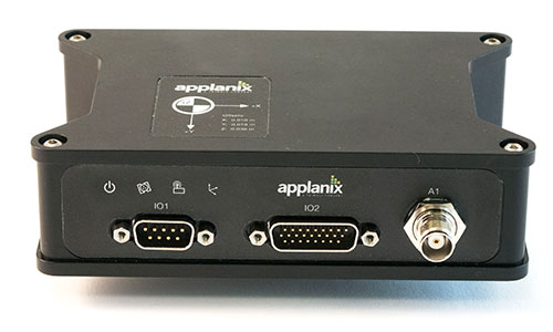
Applanix Corporation has announced the POS AVX 210, the latest addition to its airborne position and orientation portfolio for direct georeferencing of airborne mapping sensors. Using Applanix’ GNSS and inertial technology, the POS AVX 210 enables airborne surveyors to achieve gains in accuracy, efficiency and productivity for low-altitude or small form factor sensors, when compared to GNSS-only point-matching or aerial triangulation techniques.
The announcement was made at the INTERGEO 2015 conference and exhibition in Stuttgart, where Applanix is exhibiting in Hall 8, Booth C8.047.
For photogrammetric applications, the POS AVX 210 delivers highly accurate exterior orientation solutions — reducing the requirement for ground control in assisted aerial triangulation of digital single lens reflex (DSLR) or medium-format photogrammetric imagery. For low-altitude lidar applications, the POS AVX 210 provides the required precision and accuracy of direct georeferencing to enable users to generate point clouds for further refinement in adjustment software.
The POS AVX 210 is fully compatible with, and supported by, POSPac MMS, Applanix’ post-mission software for direct georeferencing of airborne mapping sensors. It is also features a seamless integration with the NanoTrack system from Track’Air, a leading commercial flight management system designed for highly efficient survey flight operations. Aircraft equipped with the POS AVX 210 and NanoTrack will be able to fly missions with reduced sidelap between flightlines, and a greatly reduced requirement for ground control points. These benefits can reduce costs and improve the efficiency of both data collection and the production of finished data sets for end users.
“With POS AVX 210, Applanix has answered a need in the marketplace for a small, compact system that enables efficient data gathering from low-cost yet highly effective sensors. These include DSLR and Medium format cameras, low-altitude lidar systems, and other systems,” said Joe Hutton, director of Inertial Technology and Airborne Products at Applanix.
POS AVX 210 consists of a single rugged enclosure containing a precision GNSS receiver and micro-electro-mechanical-system (MEMS) inertial sensors calibrated with the Applanix SmartCal technology, coupled with on-board data logging capability and interfaces for mapping sensors and flight management systems. POSPac MMS, available as an option with POS AVX 210, is a powerful GNSS-inertial processing software package that includes proprietary advanced capabilities such as the Applanix SmartBase virtual reference station, Applanix InFusion algorithms for increased productivity, and CalQC, a suite of data optimization and quality management tools.
“POS AVX 210 builds on the technological foundation of our established POS AV portfolio for large format sensors, and brings into play the innovations developed for our unmanned solutions. This combination of experience and innovation enables us to deliver a package that strikes the optimal balance between price and performance for this segment,” Hutton said.
POS AVX 210 is expected to be available in the first quarter of 2016 through Applanix’ airborne sales channels.
Trimble is partnering with unmanned aircraft system (UAS) manufacturer Multirotor service-drone, GmbH. The collaboration will allow Trimble to expand its existing UAS portfolio to provide its customers with additional solutions to choose from based on their aerial imaging project needs.
Multirotor service-drone, based in Germany, is a manufacturer of multi-rotor systems. Trimble will be Multirotor service-drone’s exclusive provider of multi-rotor vehicles for aerial mapping use in surveying, construction, mining, agriculture, oil and gas, and utilities. The combination of Multirotor service-drone’s stable and reliable platforms with Trimble’s industry-leading sensor technology and workflow efficiencies will provide customers with best-in-class solutions for aerial data capture.
Unmanned multi-rotor systems are powerful solutions for visually documenting smaller areas, vertical structures or environments where holding position is important. High-resolution imagery, orthophotos, terrain models and normalized difference vegetation index (NDVI) map deliverables created from multi-rotor data provide valuable information for the survey, engineering and agriculture industries that Trimble serves.
“We are very excited to partner with Multirotor service-drone. At Trimble we’re always looking for ways to meet our customer’s needs and enable them to solve the complex problems they encounter every day,” said Todd Steiner, product marketing director in Trimble’s Geospatial Division. “The collaboration will enable our customers to use a technology rapidly growing in popularity due to its flexibility and productivity.”
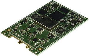
SBG Systems, a manufacturer of inertial navigation systems (INS), has selected the Septentrio AsteRx4 OEM GNSS receiver to equip its Apogee product line. The announcement was made during Ocean Business 2015, held April 14-16 in Southampton, England.
SBG Systems’ Apogee-D
“We are delighted that SBG Systems — a respected specialist in designing INS/GNSS — endorses our newly released GNSS receiver for its performance,” said, Laurent Le Thuaut, business development manager at Septentrio. “The SBG products are recognized amongst the preferred choice for accurate MEMS-based INS and we are extremely proud that our technology is included in their top of the line.”
Apogee is a new product line of high-accuracy inertial navigation systems based on robust and cost-effective MEMS technology. The INS/GNSS solution combines the latest generation of MEMS sensors and the OEM version of the AsteRx4, a newly introduced high-precision GNSS receiver from Septentrio. The Apogee series is especially suited for applications such as hydrography, mobile mapping and aerial survey where survey-grade positioning measurements are required.
AsteRx4 OEM
The AsteRx4 OEM is a multi-frequency and multi-constellation dual antenna receiver that incorporates the latest innovative GNSS tracking and positioning algorithms from Septentrio. The AsteRx4 is scalable to one centimeter and integrates the entire suite of GNSS+ algorithms proposed by Septentrio to maintain tracking during heavy vibration of machines. This assures position accuracy under difficult ionosphere conditions and mitigates or rejects intentional or unintentional interference with GNSS signals.
“The compact design and the practical and well-designed interface of the AsteRx4 allowed a seamless and an easy integration into our solutions” said Raphaël Siryani, chief marketing & sales officer of SBG Systems. “The AsteRx4 largely contributes to the robust and accurate heading as well as the reduced power consumption of the INS/GNSS Apogee products.”
Both the AsteRx4 OEM receiver and the Apogee INS/GNSS are on display at booth No. W40 (Septentrio) and booth E5c (SBG Systems) at Ocean Business.
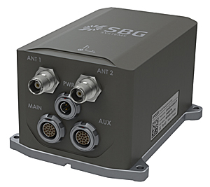
SBG Systems has released the Apogee Series, its most accurate inertial navigation systems based on robust and cost-effective MEMS technology. The INS/GNSS integrates the latest generation of MEMS sensors and a tri-frequency GNSS receiver. Apogee achieves 0.008° in roll and pitch in real-time and 0.005° in post-processing. With two antennas, it delivers a robust and accurate heading.
Four models compose the Apogee line.
The Apogee-A provides only orientation data.
The Apogee-N additionally embeds a GNSS receiver; it is a compact solution with one antenna for land and aerial applications.
The Apogee-D embeds a dual-antenna GNSS receiver for accurate heading under low dynamics conditions.
The Apogee-E delivers navigation data when connected to an external GNSS receiver or to the SplitBox with integrated GNSS.
Mobile Mapping. Apogee can be precisely synchronized with LiDAR equipment because of a UTC time-stamping accurate to 1 microsecond. This integrated INS/GNSS provides optimal position in multipath environment or during GNSS outages, thanks to a tight GNSS integration and the continuous fusion of inertial and odometer data. To get the required positioning accuracy, Apogee supports RTK and Precise Point Positioning services (Omnistar, Terrastar, and more).
Aerial Mapping and Remote Sensing. With very low noise gyroscopes, low latency, and high resistance to vibrations, the Apogee allows aerial surveys by plane or helicopter. It provides real-time orientation and position data with direct fusion of inertial and GNSS information. Compact, lightweight and low power, the Apogee is easy to install, and has an embedded web interface for configuration.
Post-processing. Orientation and position data can be recorded in the Apogee data logger. At the office, the user imports data in the post-processing software. This tool gives access to several RTK networks and reference station offline data (such as VRS and CORS.) Additionally, it enhances orientation and position accuracy by a complete “backward/forward” calculation.
“SBG Systems manufactures inertial systems from the concept to the production. The Apogee benefits from our high level of expertise in integrated design, IMU calibration, testing, and filtering,” said Alexis Guinamard, CTO of SBG Systems.
All models are available for order. Below is a promotional video with more information.
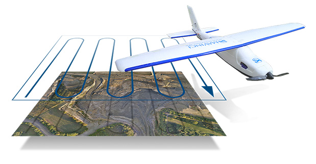
Boris Skopliak, product manager for Trimble, gives an overview of the Trimble UX5 while at the 2014 Trimble Dimensions User Conference, held Nov. 3-5 in Las Vegas, Nevada. The UX5 unmanned aircraft system (UAS) for mapping and surveying captures imagery and can generate point clouds, digital terrain models and orthomosaics.
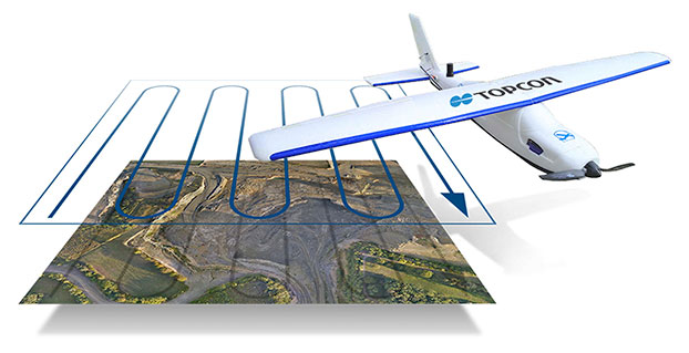
Topcon Positioning Group has released two unmanned aerial systems (UAS) for mapping — the Sirius Pro and Sirius Basic. Both systems are designed to produce the most accurate solutions for the automated mapping of a wide range of sites — regardless of terrain — including construction sites, mines and quarries, and for use in land surveying, power line and pipeline inspection as well as precision agriculture field mapping.
The fixed-wing systems resulted from a partnership with MAVinci GmbH, a UAS development company with which Topcon recently entered into a worldwide distribution agreement.
“The Sirius Pro system is unique to the UAS marketplace. Instead of using traditional ground control points, Topcon combines RTK (real-time kinematic) GNSS solutions with precision timing technology to provide more accurate mapping results when compared to other products,” said Eduardo Falcon, executive vice president and general manager for the Topcon GeoPositioning Solutions Group.
“The system is easy to use and rugged — allowing operators to use a simple hand launch with precise automatic operation from takeoff to landing, and it can be flown safely in nearly all weather conditions,” Falcon said.
The Topcon Sirius Basic is an entry-level system offering many of the advantages of the Sirius Pro with options to upgrade. “The Sirius Basic shares the same hardware components of the Pro model, providing affordability with the same level of sturdiness and ease of operation,” said Falcon. “Additionally, when the need arises for the increased accuracy and productivity of the Pro system, a simple upgrade makes the transition practically effortless.”
Both systems also offer autopilot assisted manual control, automatic flight planning and safety features.
Topcon Positioning Group has released and made available in Europe the Topcon SIRIUS PRO powered by MAVinci, an Unmanned Aerial System (UAS) designed to produce the most accurate solutions for automated mapping of construction sites, pipelines, disaster areas, mines, quarries and myriad sites without regard to terrain.
During October 2013, Topcon Europe Positioning (TEP) entered into a strategic partnership with UAS provider MAVinci GmbH. The result of that partnership is the release of the fixed-wing UAS Topcon SIRIUS PRO powered by MAVinci.
“We are excited to announce our distribution agreement with Topcon. This partnership is the ideal expansion of our global distribution network,” Johanna Claussen, CEO at MAVinci GmbH said. “The simple operation of our UAS from flight planning to the final orthophoto and DEM (Digital Elevation Model), allows flexible use in highly demanding environments. Its flexible assisted auto-pilot landing mode enables navigation around any unforeseen obstacles.”
Based in St. Leon Rot, Germany, MAVinci is a aerial surveying company specializing in the development of UAS technology.
“By adding Topcon’s RTK solutions to the UAS and ground control station, the SIRIUS PRO is the first commercially available UAS that can reach 5-cm accuracy without the need for ground control points,” said Sander Jongeleen, mobile mapping product manager for Topcon Positioning Group. “This leads to an enormous reduction of operational cost and allows mapping of areas that are not easily accessible with high accuracy.”
The SIRIUS PRO is a fixed-wing UAS capable of producing high quality and pre-positioned aerial photography without the need of extensive ground control that is required by competitive products. Key features include:
Work in mountain areas — Flight plan adapts to elevation model
Cover areas that require multiple flights — Flight plan automatically splits and rejoins for post processing
Simple hand launch
Land in areas where automatic landing is impossible with assisted auto-pilot mode
Fly in all weather conditions — wind up to 50 km/h, temperature range of -20º C to 45º C and rain.
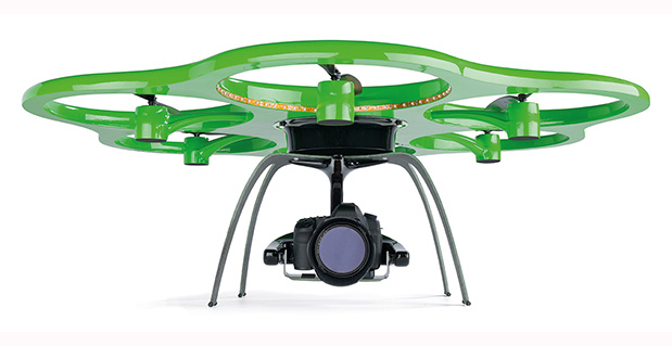
The Aibotix X6 unmanned aerial vehicle is designed to deliver up-to-date geospatial information from hard-to-reach areas.
Hexagon, a global provider of design, measurement and visualization solutions, has acquired Aibotix, a manufacturer of intelligent multicopter systems for high-efficiency aerial applications.
Headquartered in Kassel, Germany, Aibotix is the maker of Aibot X6, a new generation of vertical takeoff and landing unmanned aerial vehicle (UAV). Intelligent, autonomous and safe, the multi-rotor platform is designed to suit the needs of customers in the industrial inspection, aerial mapping, surveying, utility and security markets, Hexagon said.
UAV-based solutions are ideal for delivering up-to-date geospatial information and aiding in hard to reach areas – such as difficult infrastructure inspections of power lines, bridges and dams to locally focused mapping tasks of buildings or any vertical structure. They are quickly becoming a viable tool for key market segments that require application-specific solutions; where the UAV becomes an integral part of the workflow process, delivering essential pieces of information that drive actionable intelligence.
“The Aibotix acquisition is an important addition to Hexagon’s photogrammetric and mapping technologies portfolio,” said Hexagon President and CEO Ola Rollén. “The growing number of applications for UAV-based solutions offers huge growth potential, especially in areas that require frequent and local updates such as smart city applications, dynamic GIS, and emergency response.”
The use of a precise wide-area positioning technique for airborne trajectory solutions for LiDAR surveys provides both relative and absolute accuracies similar to those derived from using a local GNSS reference station.
Airborne light detection and ranging (LiDAR) surveys are among the most advanced means of producing high-resolution, accurate surface elevation models used for many applications in surveying and civil engineering. Precise geolocation and orientation (or georeferencing) of the LiDAR instrument with a combination of on-board GNSS and inertial sensors at the times when the measurements are made provides the key to high-quality elevation products.
The usual practice deploys reference GPS/GNSS land receivers in the area where the aircraft will be flying, to obtain a precise trajectory by short-baseline differential GNSS techniques. This could mean installing and operating receivers at many sites during a flight mission if the area surveyed is a large one.
We have tried a different approach: using as reference receivers those of a sparse network of Continuously Operating Reference Stations (CORS) in New South Wales known as CORSnet-NSW, and a wide-area differential GPS technique for obtaining the aircraft trajectory with sub-decimeter accuracy even with baseline lengths of several hundred kilometers. This may be comparable in precision and accuracy to the short-baseline method, but without the cost and logistical complications. This opens up a new level of operational capability, allowing flexibility for weather conditions and priority response applications.
The tests described here were organized and conducted by the NSW government’s Land and Property Management Authority, in collaboration with the University of New South Wales, in June 2009. CORSnet-NSW consists, at this writing, of 46 stations and by 2012 will provide statewide GNSS positioning infrastructure across NSW with a planned 70 stations in operation.
Precise Wide-Area Positioning
We used a technique for long-baseline differential, off-line positioning, able to deliver centimeter precision for fixed receivers and sub-decimeter precision for moving receivers. This choice was dictated by three considerations:
The intended application was the geolocation of the data of an airborne scanning LiDAR sensor to be used in the generation of high-accuracy digital elevation models (DEM).
Off-line processing, where all the GNSS data collected during the flight are available for processing and (as in this case) there is no need for immediate results, is intrinsically more reliable than real-time processing, where the data are available only up to the present epoch, and accurate results must be obtained right away, with no chance for a second try.
Differential processing makes it possible to resolve the carrier-phase ambiguities using well-understood methods.
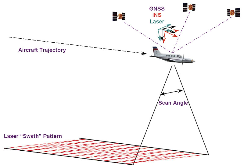
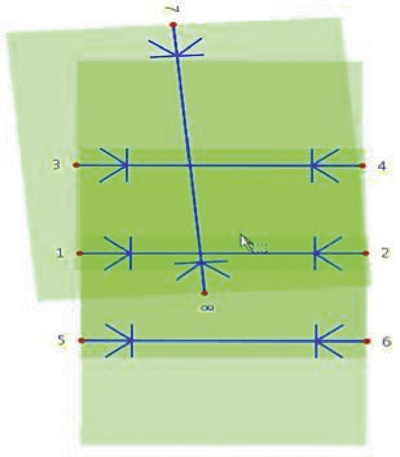
Technique. It is common practice in airborne LiDAR surveys to use GNSS both to position the instrument precisely, and to assist an inertial navigation system (INS) to obtain the orientation of the aircraft in space, as both position and orientation are needed to interpret the data properly. FIGURE 1 illustrates the relationship between the sensors used for airborne LiDAR surveys. The aircraft uses a GNSS antenna combined with an INS to georeference its trajectory. The bore-sight calibration process aligns the individual sensor orientations and standardizes the range measurements. However, if the survey is to achieve the now-expected high level of vertical accuracy (615 centimeters, 1 sigma), then the position of the GNSS/INS-derived aircraft trajectory for each laser swath must be determined with a relative precision in the order of just a few centimeters. This is achieved via differential GNSS post-processing of the kinematic airborne data together with static observations collected on precisely surveyed ground reference stations. The GNSS positions are then blended with high-frequency measurements taken by the onboard INS to produce the final trajectory and reference orientations.
Figure 1. Airborne LiDAR reference frame.
To such ends, the aircraft trajectory is usually determined by short-baseline differential GNSS, with ground receivers deployed near the intended flight path of the aircraft. In this way it is possible to use GNSS data analysis techniques that are both precise and quite straightforward to implement in software. The simplicity of these techniques is possible because, in short-baseline differential solutions, the data of the aircraft receiver and any nearby network receivers have much the same systematic errors (due to such things as satellite ephemerides errors, transmission delays, and so on) that cancel out — or nearly so — when their observations are differenced between them. This also makes it possible to resolve quickly and reliably the cycle ambiguities in the observed carrier phase, the most precise type of GNSS data, overcoming one of the main obstacles to obtaining good results. Furthermore, it is possible to get such results with single-frequency receivers, as ionospheric delay is one of the systematic effects that can be largely canceled out.
In wide-area solutions, those cancellations are not complete enough to ignore the systematic data errors, and they have to be included in the form of additional unknown parameters in the observation equations. Also, it is necessary to account for the ionospheric delays using dual-frequency data, which means using more expensive GNSS receivers and antennas.
Resolving the carrier-phase ambiguities is no longer straightforward or assured. The standard way of dealing with the ambiguities is to include them as unknowns in the observation equations and adjust them along with the other unknowns: this is often referred to as “floating the ambiguities.” Fixing (or resolving) those ambiguities to their most likely integer values in a matter of seconds to a minute is possible on occasion, when the aircraft is within less than 20 kilometers from a ground receiver, or very precise corrections for the ionospheric delay are available; otherwise slower techniques, that require tens of minutes, may be used. It is also necessary to correct as well as possible such things as the neutral atmospheric delay of the GNSS radio signals, the movement of the “fixed” stations due to plate tectonics, the solid earth tide using mathematical models, and, in the case of the tropospheric delay, estimating the error in the corrections made using a standard formula as an additional unknown per receiver.
Over the years all these difficulties have been gradually dealt with more effectively, more efficiently, more reliably and, from the user’s point of view, less painfully. Originally developed for the repeated determination of station positions to measure the slow tectonic deformations of the Earth’s crust, and to calculate precisely the orbit of Earth-observing satellites, these days, after nearly 30 years of steady progress, GNSS wide-area techniques and the corresponding software find many applications in science, engineering, and navigation, and are becoming widely used in remote sensing.
Software. We used the Interferometric Translocation (IT) wide-area positioning software developed by one of us for the long-baseline aircraft trajectory solutions and also to re-position in the IGS05 international reference frame some CORSnet-NSW stations, so their data could be used consistently in the differential wide-area solutions. These stations were originally given in the Geocentric Datum of Australia (GDA94). For both purposes we used the precise final GPS orbits computed and distributed by the IGS.
To validate the aircraft trajectories calculated with the wide-area method, we relied mainly on the quality of the LiDAR DEM results obtained with those trajectories. We also used commercial software to generate short-baseline differential solutions with receivers deployed near the intended aircraft flight-path, as is common practice in this type of survey, and compared them with the wide-area solutions (they turned out to be quite similar to short-baseline solutions obtained with the wide-area software).
Airborne Tests
This study has used data from two airborne LiDAR surveys conducted by the NSW Land and Property Management Authority (LPMA) in June 2009. The first took place near the township of Glen Innes, and the second was a bore-sight calibration flight near the city of Bathurst. For both LiDAR surveys, the following data were acquired:
Aircraft trajectory, raw dual-frequency GPS (1 Hz) and IMU data (200 Hz).
LiDAR (raw return data for each laser pulse).
GPS reference station data from local receivers and multiple CORSnet-NSW sites.
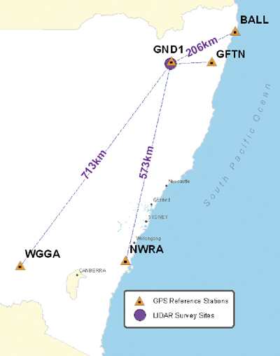
Glen Innes Test. This operational LiDAR survey established GND1 as the local reference station within the survey area. CORSnet-NSW data were collected for the test from GNSS receivers in Ballina (BALL), Grafton (GFTN), Nowra (NWRA), and Wagga Wagga (WGGA). FIGURE 2 shows the distribution of the reference stations and the flight runs.
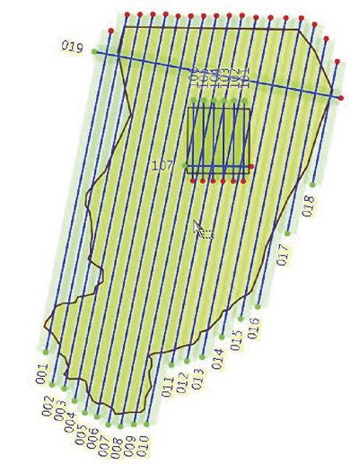
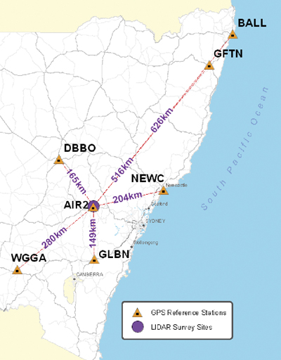
Figure 2. Glen Innes survey of June 9, 2009, showing the distribution of reference stations with baseline lengths and the survey area with (numbered) flight runs.Bathurst Test. Bathurst Airport is LPMA’s LiDAR calibration site and has various arrays of accurate ground checkpoints. AIR2, near the runway of the Bathurst airport, is the locally established GNSS reference station. CORSnet-NSW data were collected for the test from receivers in Ballina (BALL), Dubbo (DBBO), Grafton (GFTN), Newcastle (NEWC), Nowra (NWRA), and Wagga Wagga (WGGA). FIGURE 3 shows reference-station distribution and a schematic of the flight runs.
Figure 3. Bathurst test of June 16, 2009, showing the distribution of reference stations with baseline lengths and the survey area with (numbered) flight runs.
Effect on LiDAR Data
Rather than simply comparing aircraft trajectories, this study aimed to determine what effect the use of wide-area GNSS positioning has on the actual LiDAR point data and associated elevation surfaces. In terms of the horizontal accuracy required for LiDAR surveys, initial tests showed that the differences between the horizontal positions of various trajectories was negligible; therefore, only the vertical component was considered in this analysis.
To quantify differences between LiDAR data generated from trajectories using various combinations of distant GNSS reference sites, we applied four types of analysis:
Comparison of trajectories — directly compare the locally computed trajectory (assumed to be truth) with each wide-area derived trajectory.
Relative LiDAR point comparison — compare the positions for a sample of LiDAR ground points derived from the locally computed trajectory with those derived from each wide-area derived trajectory.
DEM comparison — difference the raster surfaces derived from the locally computed trajectory and a wide-area derived trajectory to find the effect over a LiDAR run.
Absolute LiDAR ground control comparison — compare the LiDAR derived surface from various trajectories to the surveyed ground control (Bathurst Calibration test site only). This also involves vertically shifting the resulting surface so that its offset relative to the one used as control is zero, thus removing the effect of using different reference frames for the GNSS trajectories and the control surface.
Trajectory Comparison
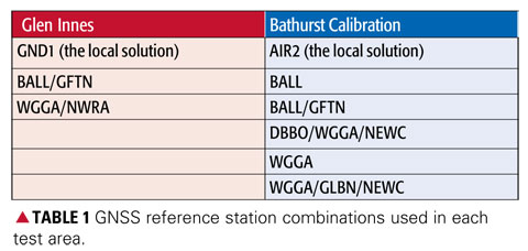
The comparison between the locally determined and each wide-area derived trajectory was made along the entire trajectory for each flight. The importance of this step lies in the assumption that all LiDAR data are directly positioned from the trajectory and so any systematic effect in the trajectory should be reflected on the ground. For each test site the locally derived solution is assumed to be “truth” with the vertical difference computed against wide-area solutions for each combination of reference stations used (TABLE 1).
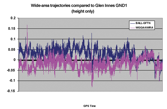
Glen Innes Test. FIGURE 4 shows the vertical comparison of two wide-area derived trajectories (using BALL and GFTN, and WGGA and NWRA, respectively) against the locally derived trajectory (using GND1). It can be seen that once the aircraft attained its stable operating altitude, the wide-area derived trajectories are generally within 5 centimeters of the locally derived solution.
Figure 4. Trajectory elevation differences for entire Glen Innes flight.
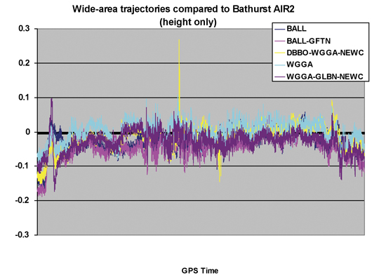
Bathurst Test. The Bathurst test differs from the Glen Innes test in that both the duration of the flight and the length of each run are significantly shorter. FIGURE 5 shows the vertical component of five wide-area derived trajectories, using several combinations of CORSnet-NSW reference stations, compared against the locally derived trajectory (using AIR2). The results once again show a remarkably consistent comparison with the locally derived solution. Data spikes showing up in the DBBO/WGGA/NEWC (yellow) solution were attributed to small data glitches at the DBBO CORSnet-NSW site. Unfortunately, LiDAR data were not collected at those instances; therefore, the effect on ground data could not be fully assessed.
Figure 5. Trajectory elevation differences for entire Bathurst calibration flight.
Relative Comparison
Regardless of the trajectory and orientation used to georeference LiDAR data, the same number of points will be created. It is therefore possible to create a LiDAR dataset using the same raw LiDAR data but different GNSS trajectories, and compare the results to determine the relative positioning differences on the ground.
Given the large number (many millions) of points in a LiDAR dataset, we used a representative sample of evenly spaced 10 2 10 meter areas each containing 50–100 points (on level ground) for statistical analysis. We calculated displacement vectors between points computed from the locally derived trajectory and those using wide-area trajectories. Results from flight run 002 at Glen Innes (see Figure 2) and run 7 at the Bathurst Calibration test site (see Figure 3) are presented here.
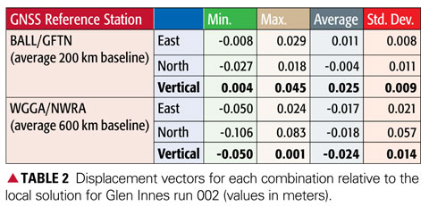
Glen Innes Test Run 002. The displacement vectors from 46 sample areas (4,620 points) are summarized in TABLE 2, being points computed using the two wide-area solutions compared with the locally derived solution using reference station GND1. Note the high accuracy achieved in the all important vertical component.
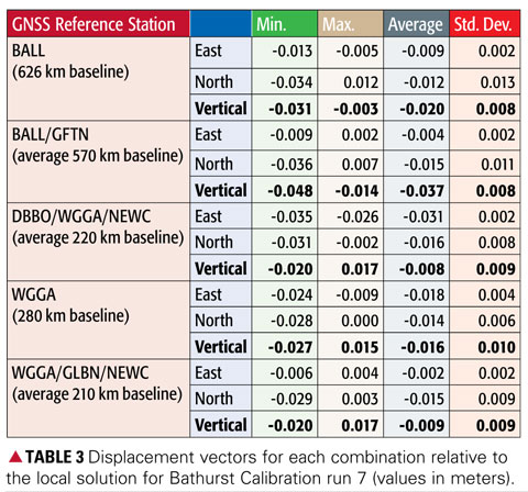
Bathurst Test Run 7. The displacement vectors from 25 sample areas (1,700 points) are summarized in TABLE 3, being points computed using the five wide-area solutions compared with the locally derived solution using reference station AIR2. Once again the results clearly show that the height values agree to within a few centimeters, even over baselines of more than 600 kilometers in length.
DEM Comparison
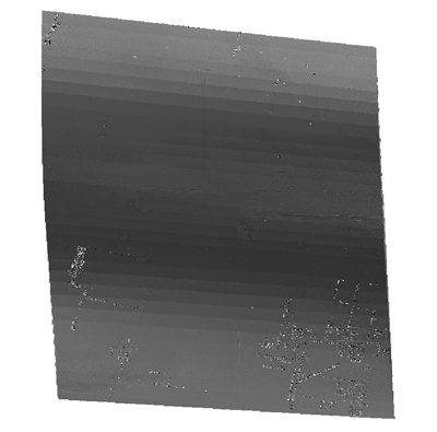
To investigate how the LiDAR surfaces derived from each trajectory compare across the entire data swath, we created raster surfaces from the LiDAR point data. Each surface was then subtracted from the local solution to create a difference surface. Visual inspection and interpretation was then used to discern any patterns or effects.
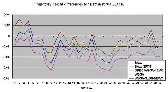
The result shown in FIGURE 6 (Bathurst Calibration flight run 7) was typical of the cyclical effect evident for all solutions. The magnitude of the difference was in the order of 2–3 centimeters and is in the direction of flight (north to south). If this cyclical variation is compared with the trajectory comparison for just the 33-second duration of flight run 7, a clear (expected) correlation with the variation in height is evident (FIGURE 7).
Figure 6. Subtraction surface for Bathurst Calibration run 7 (AIR2 vs. BALL).Figure 7. Trajectory comparison for Bathurst Calibration run 7 (031318).
No DEM comparison results are presented for the Glen Innes data because of significant variation in terrain and vegetation, making interpolation difficult and unreliable.
Absolute LiDAR Comparison
Ground control points serve two purposes in a LiDAR survey:
The calculation of statistics to describe vertical accuracy, that is, quantifying the match of the surface to the local height datum.
The calculation of a surface adjustment to enable transformation of the LiDAR points to fit the local height datum.
Additionally, ground control points with accurate heights are used to calibrate the sensor before use in active LiDAR surveys to account for internal electrical delays in the ranging and measurement system. LPMA maintains a calibration site at Bathurst Airport for this purpose, and regularly surveys the area to ensure the sensor is operating at maximum accuracy. It should be noted that the sensor was calibrated using Bathurst Airport ground control data prior to this study.
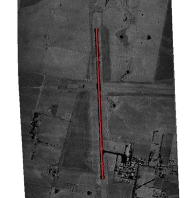
Surveyed Ground Control. The airport runway centerline vertical profile for the Bathurst Calibration site (FIGURE 8) was re-computed in terms of the same IGS05 reference frame determined for the LiDAR trajectories, thereby allowing an independent comparison with ground truth.
Figure 8. Runway vertical profile at the Bathurst Airport calibration site.
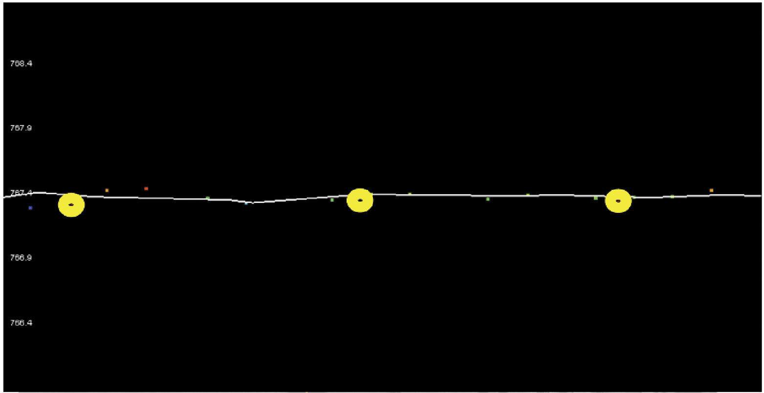
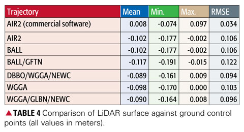
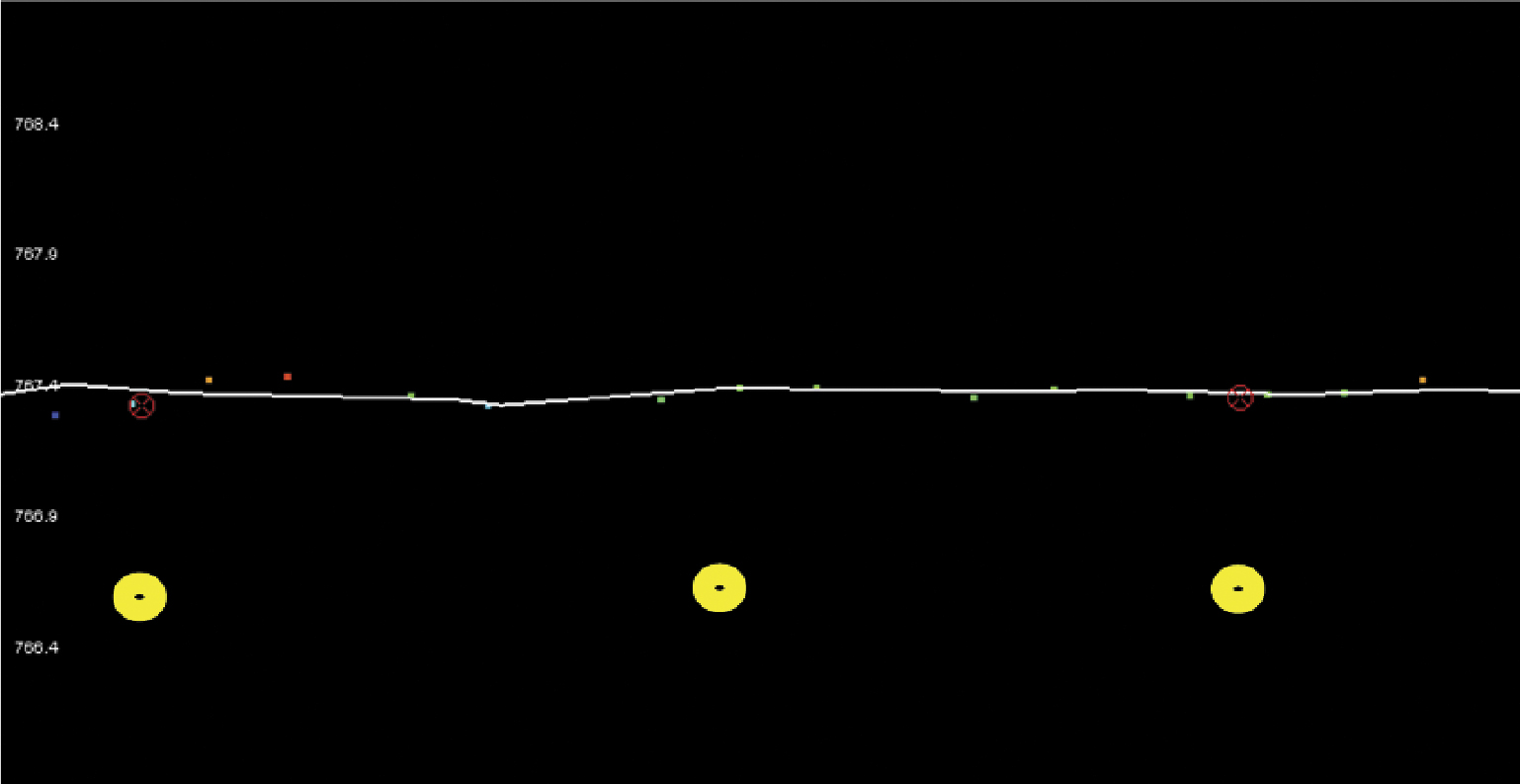
Point Comparison. Data from Bathurst run 7 were used to compare LiDAR results with the established ground control using a basic triangulated irregular network (TIN) surface comparison (FIGURE 9 and TABLE 4). In Figure 9, the TIN surface is indicated by the white line, while the ground control points are shown with yellow buffers.
Figure 9. Comparison of LiDAR surface and ground control points.
The first trajectory in Table 4 is the original calibration comparison using commercial software and orthometric height data. All wide-area solutions display a similar vertical offset, because of the use of different reference frames for the GrafNav and wide-area solutions (IGS05 vs. GDA94), and differences in the implementation in software of, for example, antenna corrections and atmospheric modeling. At first glance, the significant differences to the GrafNav trajectory caused the wide-area result to not satisfy the accuracy specifications for LiDAR. However, had the wide-area solutions been used for the sensor calibration, the figures would have been much closer to the ground truth.
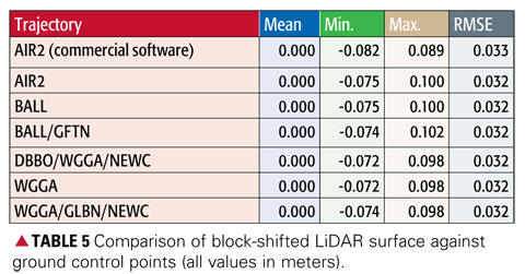
Block-Shifted Data Comparison. In an operational environment, because of systematic errors in the resulting DEM relative to the local height datum, this mean vertical offset is a common occurrence with comparisons against ground control similar to those shown in FIGURE 10. Again, the TIN surface is indicated by the white line, and the ground control points are shown with yellow buffers.
Figure 10. Usual operational comparison of LiDAR surface and ground control points.
In standard LiDAR operations, the mean vertical offset between the initial results and the ground control, at the control points, produces a zero-mean offset. Following this procedure in this case results in the variation in the comparison of LiDAR data with ground truth now being well within the required limits of 615 centimeters (TABLE 5). The values show that after a block shift, trajectory solutions are virtually identical with a root mean square error of 32 millimeters. Thus, local GNSS reference stations can be replaced by distant CORS sites without loss of accuracy.
Conclusions
A precise wide-area positioning technique for airborne trajectory solutions provides both relative and absolute accuracies similar to those derived from usinga local GNSS reference station. Irrespective of which reference sites are used and once calibration and antenna modeling issues are addressed, the absolute comparison with ground control is well within the required accuracies. With the configuration of a GNSS network such as CORSnet-NSW (when complete, at least one site will always be within 150 kilometers of any point within New South Wales), an airborne LiDAR survey in the network’s service area can provide data for computation of an accurate sensor trajectory. This potentially negates the need to place and maintain ground reference stations close to the survey area — an exercise which not only requires significant resources but also reduces the operational flexibility of the aircraft.
The challenge for this technique in an operational environment is to define and maintain a precise reference frame for all CORSnet-NSW sites and observations, including the use of a stable ellipsoidal height datum with compatible geoid modeling in order to provide local orthometric elevation data. The knowledge base required for computation of wide-area GNSS solutions is significant and requires understanding of geodesy, GNSS positioning, absolute antenna modeling, application of precise ephemerides, and derivation of the other parameters inherent to successful ambiguity resolution over long distances.
Regardless of processing method, a LiDAR survey will always require independent ground surveys for collection of vertical checkpoints, which provide quality control to ensure the accuracy meets specifications, and the means to define any transformations necessary to fit LiDAR data with local height datum.
Manufacturer
NovAtel’s WayPoint GrafNav software was used for comparison purposes.
The ”IT” Software
Runs under Windows, Unix, Linux, and FreeBSD.
Source code compatible with most Fortran compilers.
Follows the IERS 2003 conventions.
Available mainly for collaborative research purposes, with a Free Software Foundation General Public Lice
nse.
Stop-and-go for rapid mobile surveys with pre-surveyed waypoints.
Differential, precise point positioning, mixed mode (precise differential + point positioning).
Data corrected for: Earth tide, neutral atmosphere radio signal delays, carrier phase windup, and so on.
Estimated parameters:
Receiver position in the IGS05 reference frame, with the WGS84 reference ellipsoid, earth spin-rate, light speed, GM constant.
Biases in ionosphere-free carrier-phase linear combination (“floated” ambiguities).
Neutral zenith delay correction error.
Broadcast orbit errors (allows precise differential near-real time solutions).
Integer ambiguity resolution available in differential mode, with short baselines up to 20 kilometers (in minutes), and baselines of unlimited length (in tens of minutes — or just minutes, with a precise ionosphere correction).
Oscar L. Colombo received a degree in electrical engineering from the National University of la Plata, Argentina, and a Ph.D. in electrical engineering from the University of New South Wales, Australia. He is an independent consultant.
Shane Brunker is an airborne LiDAR and imaging specialist working in a consulting capacity for specialized LiDAR survey company Network Mapping (United Kingdom).
Glenn Jones is a senior surveyor at the NSW Land and Property Management Authority in Bathurst, Australia.
Volker Janssen is a GNSS surveyor (CORS Network) in the Survey Infrastructure and Geodesy branch at the NSW Land and Property Management Authority in Bathurst, Australia. He holds a Ph.D. from the University of New South Wales.
Chris Rizos is head of the School of Surveying and Spatial Information Systems of the University of New South Wales, has a surveyor’s degree and a Ph.D. from the same university, and is an specialist in geodesy and GNSS positioning.