Chip-scale atomic clocks can supplement GNSS receivers to provide accurate and reliable time in GNSS-challenged environments. Photo: Microchip Technology
Accurate and reliable time is just as important as accurate and reliable location for a wide range of military and civilian applications — and GNSS receivers cannot provide either one when they are jammed. For timing, one solution is to supplement GNSS receivers with a miniature atomic clock. We asked Microchip Technology a few questions about their chip-scale atomic clock (CSAC) and Stewart Hampton, the company’s senior product line manager, responded.
How long was your SA65 CSAC in development before you announced it in August 2021? Typically, how often do you launch a new CSAC?
CSAC development started in 2001 under a contract from DARPA with Draper and Sandia laboratories. CSAC was first introduced to the commercial marketplace in 2011, and in 2016 we released an improved product design with an operating temperature range of –10 C° to +70 C°. Last year we released our CSAC SA65 with a wider operating temperature range, faster warm-up and improved frequency stability aimed at the defense and industrial marketplace. So, it has been about five years between major CSAC releases, but that may not be indicative of future products because we have also introduced specialized CSAC versions, such as the Low Noise CSAC (LNCSAC) in 2014 and the only commercially available radiation-tolerant CSAC (Space CSAC) in 2018.
What is the CSAC SA65’s drift rate?
Its typical drift rate is specified at <9 × 10⁻¹⁰ per month. Another key specification, particularly for many portable military applications, is total sensitivity of frequency to temperature (tempco) over a specified range. For the CSAC SA65, that specification is ±3 × 10⁻¹⁰ over the entire operating temperature range of –40 C° to +80 C °.
What are a few specific military use cases?
CSAC is designed into multiple military programs and used in a wide variety of military applications, particularly in GNSS-denied environments — including assured positioning, navigation and timing (APNT) modules, underwater unmanned and autonomous vehicles, software-defined radios, man-portable transceiver-based military communications, vehicle management computers, airborne reconnaissance/UAVs and GNSS-disciplined oscillators. It is also used in command, control, communications, computers, cyber, intelligence, surveillance and reconnaissance (C5ISR). The space CSAC variant is commonly used on low-Earth-orbit space defense payloads supporting such applications as low-latency communications networks, RF geolocation (geointelligence, or GEOINT), optical time transfer, alternative PNT satellites and Earth observation.
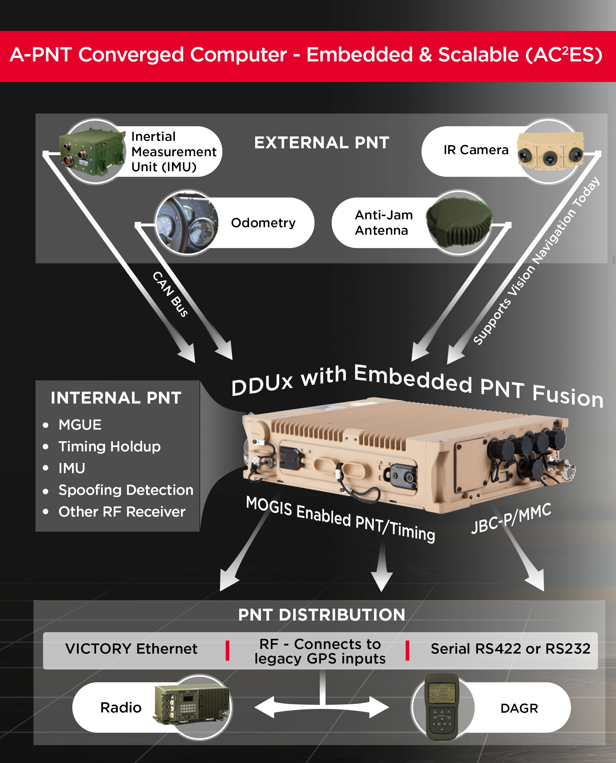
Leonardo DRS’ A-PNT Converged Computer – Embedded & Scalable (AC²ES) adds capabilities to its widely used DDUx. Photo: Leonardo DRS
To help counter attacks that degrade GNSS capability on combat vehicles, Leonardo DRS developed a modified data-distribution unit computer, the DDUx II, with an embedded assured positioning, navigation and timing (APNT) capability the company calls Assured Positioning, Navigation and Timing Converged Computer Embedded & Scalable (AC²ES). It augments standard military GPS PNT sources with technologies such as anti-jam, anti-spoof, M-code receivers, additional RF sources, vehicle infrared (IR) sensor vision navigation, wheel rotation and inertial measurement units (IMUs). It also offers a choice of multiple timing holdup modules that increase accuracy proportionately with cost.
The DDUx II and military variants, fielded by the U.S. Army and Marine Corps, allow for integration of APNT functionality with the Battle Management System (BMS). It can provide APNT distribution to all other devices needing PNT within the vehicle without adding to its size, weight and power (SWAP).
Following a five-year development program, Leonardo DRS launched the AC²ES in September 2021 as a commercial option while continuing discussions with the U.S. Army and Marine Corps, which have not yet adopted it. “We have tested it,” said Mike Stucki, business development manager for the company’s land electronics division. “We have gone to Army jamming and testing events. We have performance and results. However, it has not been officially tested under the Army or Marines programs, with which we are moving forward this year.”
Leonardo DRS wants to offer the armed services the additional components they need to achieve APNT “and not require them to buy anything they don’t need or want,” Stucki said. Those additional components include multiple GNSS receivers for timing and a low-end internal IMU to provide continuous navigation in case GNSS is disrupted. All these components fit directly into the existing DRS hardware. Under the Mounted Family of Computer Systems (MFoCS) program alone, the Army has fielded more than 100,000 DDUx units. Some vehicles already have high-end INS, wheel encoders, and other sensors, and MFoCS can ingest their data.
Navigating with Infrared
For vision navigation, Leonardo DRS uses software developed by its partner Leidos that ingests data from existing hardware on the vehicles, many of which already have IR cameras. In a GNSS-denied environment, this enables the system to navigate by matching what the IR camera sees to an imagery database. Leidos’ software is based on work it began in 2011 with the DARPA All-Source Positioning and Navigation (ASPN) program.
“Leidos developed algorithms that use these other sensor inputs in the sensor-fusion engine to provide more accurate absolute positioning in a completely RF-denied environment,” said Kevin Betts, PNT director for Leidos. “We take the live images from the vehicle’s existing IR camera and match them to a satellite-derived model of the environment. When the images match, we have an absolute position update that we can provide to the navigation filter.”
MFoCS “is the heart that runs the Blue Force tracker system that the soldiers use,” said Bart Blanchard, director of advanced programs at Leonardo DRS. “We’ve added the APNT components inside that box. They’re leveraging the hardware that they already own. It’s a very cost-effective solution.”
A roundup of recent products in the GNSS and inertial positioning industry from the February 2022 issue of GPS World magazine.
OEM
GNSS Receiver
For tracking, telematics
Photo: u-blox
The LENA-R8 GNSS receiver is based on the u-blox M10 platform. The compact module balances cost and performance with a single antenna and primarily targets customer deployments in the Europe, Middle East, Africa, Asia, and South America regions. Designed for tracking and telematics, the module series was designed to minimize material costs and data charges. The LENA-R8 supports a broad range of frequency bands with 2G fallback, providing maximum roaming coverage for global tracking applications using a single stock keeping unit (SKU).
The low-profile triple-band HC997EXF embedded helical GNSS antenna features eXtended Filtering (XF). It is designed for precise positioning, covering the GPS/QZSS-L1/L2/L5, GLONASS-G1/G2/G3, Galileo-E1/E5a/E5b, BeiDou-B1/B2/B2a, and NavIC-L5 frequency bands. It also covers regional satellite-based augmentation systems (WAAS, EGNOS, MSAS, GAGAN) and L-band correction services. It is packaged in a light (11 g), compact form factor (60 x 25 mm). Its precision-tuned, high-accuracy helical element provides an excellent axial ratio and operates without a ground plane, making it suitable for lightweight unmanned aerial vehicle (UAV) navigation and a wide variety of precision applications.
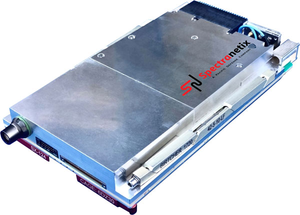
The SX-124 ruggedized 3U OpenVPX high-performance positioning, navigation and timing (PNT) card can provide timing and positioning information in a GPS-denied environment through sensor fusion. It is designed for highly integrated systems with a requirement for the U.S. Army’s C5ISR Modular Open Suite of Standards (CMOSS) and alignment with the Open Group Sensor Open Systems Architecture (SOSA) technical standard. The SX-124 can accept external sources or use its onboard GNSS receivers as reference inputs for timing and positioning data. The positioning data can be fused with internal and external inertial measurement units.
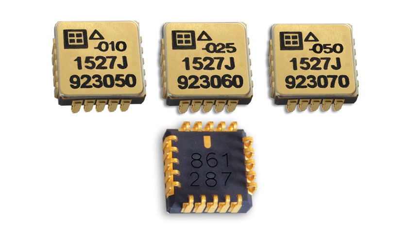
The Model 1527 series is a family of miniature, radiation-tested, tactical-grade micro-electromechanical (MEMS) accelerometers. Offered in three full-scale acceleration ranges — ±10 g, ±25 g and ±50 g — the series is designed to support a variety of critical space electronics testing requirements, including those of spacecraft, satellites and CubeSats. Their small bias and scale-factor temperature coefficients, excellent in-run bias stability and zero cross-coupling make the Model 1527 series particularly well-suited for spacecraft electronics testing applications requiring low power consumption (+5 VDC, 6.5 mA), low noise, long-term measurement stability in –55° C to +125° C environments, and performance reliability under intermittent radiation exposures.
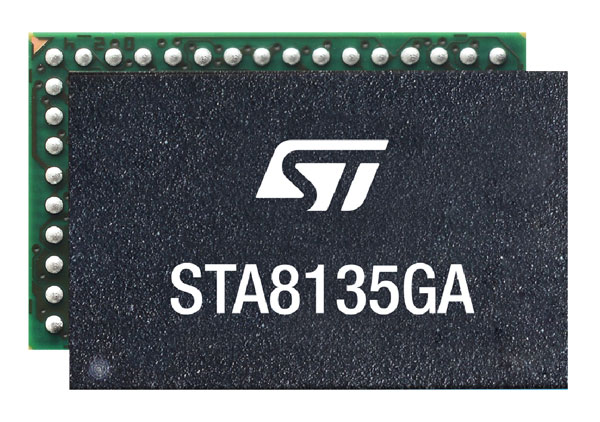
The STA8135GA automotive-qualified GNSS receiver is designed to deliver the high-quality position data needed by advanced driving systems. Part of the Teseo V family, the STA8135GA integrates a triple-band positioning measurement engine. It also provides standard multi-band position-velocity-time (PVT) and dead reckoning. The multi-constellation receiver delivers raw information for the host system to run any precise-positioning algorithm, such as PPP/RTK (precise point positioning/real-time kinematic). The receiver can track satellites in the GPS, GLONASS, BeiDou, Galileo, QZSS and NAVIC/IRNSS constellations.
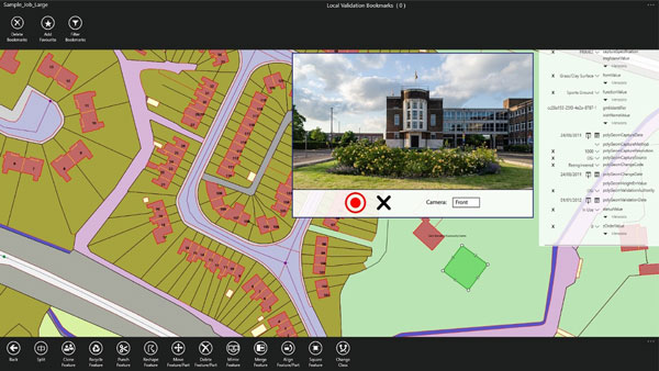
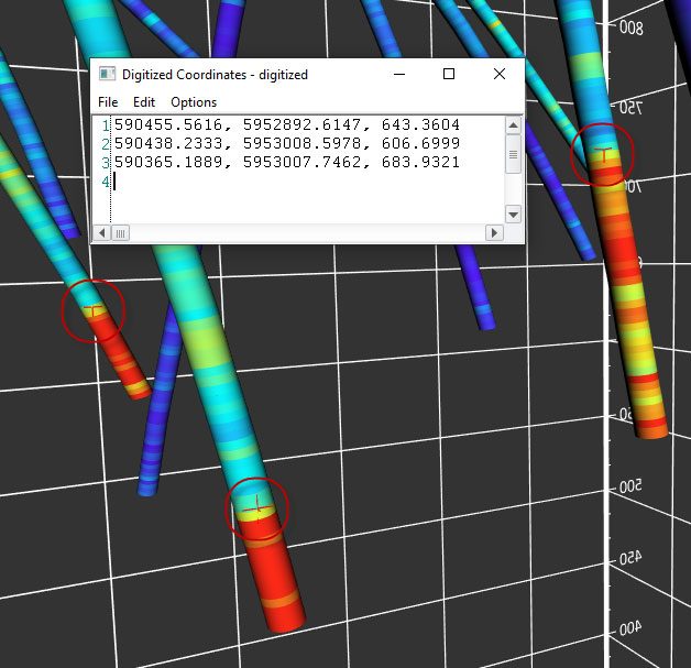
Survey application 1Edit now has increased support for photos and 2.5D data. 1Edit 3.1 allows users to attach feature photos, including automated geotagging, which enables surveyors to visualize assets and fine tune observations. Also included are new validation functions and improved handling for heights (2.5D data), typically useful for detailed asset and land-management surveys. Enhanced styling, including bitmap fills and dashed lines, make it easier to identify and classify different asset types during surveys. Additional control of editable layers and fields provides protection for non-editable data and protects the data quality. Significant improvements to rendering of thematic mapping enhances the speed and fluidity of the intuitive user interface.
The latest version of Surfer surface mapping software has improved map-making functionality and data exporting capabilities. Surfer is used by more than 100,000 people worldwide, many involved in oil and gas exploration, environmental consulting, mining, engineering and geospatial projects. It provides fast and powerful contouring algorithms, enabling users to model data sets, apply an array of advanced analytics tools, and graphically communicate the results. Frames now have outlines and background fill colors to make them easier to read when placed on top of maps and attribute data can now be exported as numeric data.
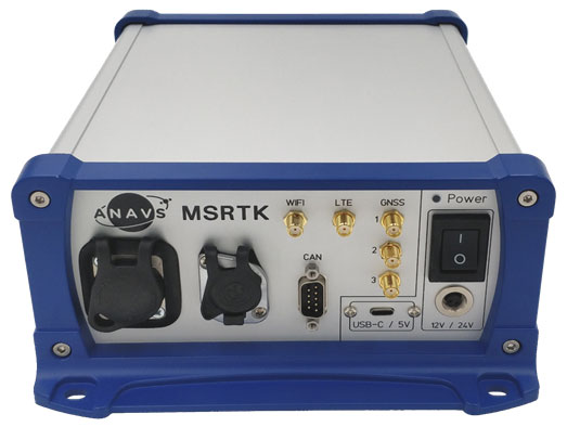
The Multi-Sensor (MS-) RTK/PPP device is a turnkey system easily integrated into surveying applications. The module includes up to three multi-frequency, multi-GNSS (GPS + Galileo + Glonass + BeiDou) receivers, a MEMS IMU, a barometer, a CAN interface for reception of vehicle data (wheel odometry and steering angle), and an LTE module for reception of RTK/PPP corrections. ANavS sensor fusion performs tight coupling of all sensor data with an Extended Kalman Filter (EKF). Various interfaces can connect additional sensors (such as camera or lidar) or output position information.
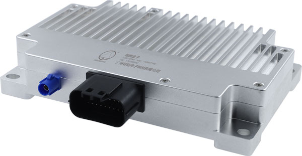
The HD-MapBox integrates high-precision map data based on high-precision positioning. Fusing data from a GNSS receiver, IMU, ADAS camera, vehicle dynamics and HD maps, the HD-MapBox can achieve a lateral error of less than 8 inches (0.2 meters) and a longitudinal error of less than 6.5 feet (2 meters) with a 95% confidence interval, providing an accurate reference for highway pilots and automated valet parking. Even if both GNSS and lane line detection are not available, the HD-MapBox can still enable vehicles to keep inside the lane for at least a quarter mile (400 meters).
Esri ArcGIS IPS is an indoor positioning system that adds a blue dot to indoor maps, enabling users to locate their current position inside a building in the same way GPS enables outdoor location indicators. It uses an alternative technology to enable real-time positioning and navigation inside buildings. It also provides live location sharing and tracking, location data capture and analytical insights. ArcGIS IPS is available for users of ArcGIS Indoors, an indoor mapping system for smart building management, and ArcGIS Runtime SDKs, which enable the indoor positioning capability in custom-built apps.
A roundup of recent products in the GNSS and inertial positioning industry from the January 2022 issue of GPS World magazine.
Surveying
Base Station
Receives all available GNSS signals
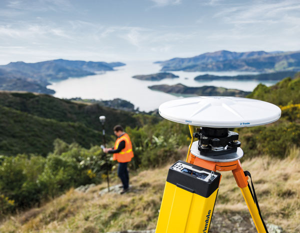
Photo: Trimble
The Trimble R750 GNSS modular receiver is a connected base station for use in civil construction, geospatial and agricultural applications. The R750 provides high-accuracy base-station performance, giving contractors, surveyors and farmers more reliable and precise positioning in the field. The R750 also can be used to broadcast real-time kinematic (RTK) corrections for a wide range of applications, including seismic surveying, monitoring, civil construction, precision agriculture and more. Access to all available satellite signals provides improved performance and reliability when used with a Trimble ProPoint GNSS rover. ProPoint gives users improved performance in challenging GNSS conditions, with improved signal management.
Trimble, trimble.com
Flight Planning
Updated for safer UAV surveying
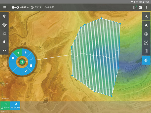
Photo: Microdrones
The mdCockpit app was designed for professional drone users to make it easy to plan, monitor, change and control flights from an Android tablet. The updates in version 2021.3 include features that improve flight safety and give more options for surveying with an aim to deliver a premier solution for planning, monitoring, adjusting, analyzing and controlling professional drone flight missions from a tablet. Updates include an improved flight editor, flight data collection and drone configuration. Drone pilots can download mdCockpit through the Google Play store.
Microdrones, microdrones.com
OEM
LTE Module
With 2G fallback for Latin America
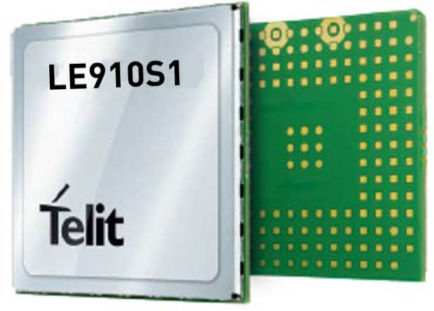
Photo: Telit
The LE910S1-ELG LTE Cat 1 module is designed for internet of things (IoT) applications in Latin America that need a combination of performance, affordability and voice support in a compact form factor. It provides 2G fallback, making it suitable for areas that have not upgraded to 4G. With an embedded GNSS receiver, the cost-optimized LE910S1-ELG is suitable for tracking applications such as fleet management, stolen-vehicle tracking and recovery, and other mobile IoT applications that need to maintain a reliable connection when moving around in a country, region or multiple regions. The power-saving embedded GNSS receiver enables the use of GNSS positioning even when the cellular modem is switched off.
Telit, telit.com
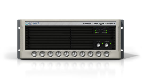
Flex Power
Capability now on constellation simulator
Photo: Spirent
A new positioning, navigation and timing (PNT) test capability commonly referred to as programmable power — or flex power — is available on the Spirent GSS9000 constellation simulator and can be applied to existing scenarios. Flex power is the reallocation of transmit power among individual signals in GPS satellites, providing a countermeasure against GPS jamming. Spirent simulators fully support programmable power for M-code, Y-code and C/A (coarse acquisition) code.
Spirent, spirent.com
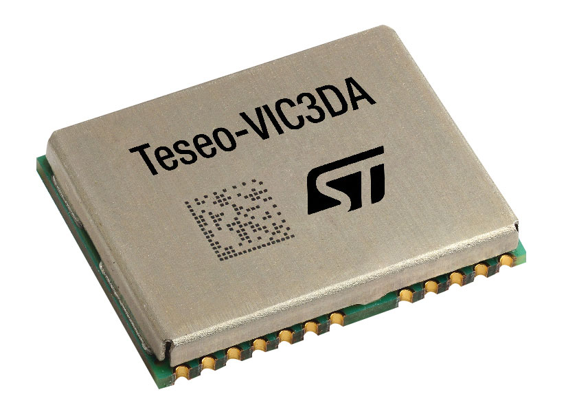
GNSS Module
Automotive qualified with INS and dead reckoning
Photo: STMicroelectronics
The Teseo-VIC3DA is the latest member of the Teseo module family, designed for vehicle positioning. It combines the Teseo III GNSS integrated circuit with the 6-axis MEMS inertial measurement unit (IMU) and dead-reckoning software to provide super-high-resolution motion tracking for advanced vehicle navigation and telematics applications. Teseo III offers robust positioning capabilities by simultaneously receiving signals from GPS, Galileo, GLONASS, BeiDou and QZSS constellations. The module enables competitively priced in-car navigation, fleet management and insurance-monitoring applications.
STMicroelectronics, st.com
PNT Platform
Protects critical infrastructure from GNSS vulnerabilities
Photo: ADVA
The scalable aPNT+ platform meets the latest guidelines for resilient positioning, navigation and timing (PNT), providing end-to-end control and timing network visibility for robust protection against the catastrophic risks that PNT disruption poses to national security and essential assets such as power grids. Even without GPS or GNSS timing, the solution provides an intelligent, end-to-end self-recovery system designed around a three-fold framework, integrating multi-layer detection, multi-source backup and multi-level fault-tolerant mitigation.
ADVA, adva.com
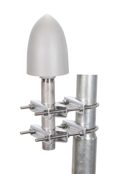
Timing Antennas
IP67-compliant for outdoor and marine environments
Photo: RadioWaves
A new series of GPS/GNSS timing antennas cover the L1 and L5 GPS bands, providing axial ratio and higher accuracy for the reception of satellite timing signals and reference frequencies for enhanced phase synchronization in precision network deployments. Their high gain, low noise figure of 2-dB and high out-of-band rejection allows for use of longer and cost-effective cables for easy and flexible installations. Built-in surge protection supports a wide range of GNSS including GPS, GLONASS, BeiDou and Galileo, as well as Iridium.
RadioWaves, radiowaves.com
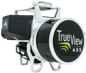
Mapping
Imaging System
Designed for utility and infrastructure mapping
Photo: Geocue
True View 435 is an economical platform for utility-grade mapping, with superior ground-capturing capabilities for lightly vegetated areas. The next-generation compact 3D imaging system has the sensitivity needed for infrastructure mapping. Its position and orientation system is the Applanix APX-15, achieving accuracy of better than 5 cm RMSE and precision of better than 5 cm at 1 sigma.
GeoCue, geocue.com
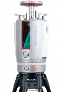
Long-Range Scanner
Includes integrated GNSS receiver
Photo: Riegl
The VZ-2000i long-range 3D laser scanning system combines user friendliness with fast, accurate data acquisition. The flexible system includes an integrated GNSS unit for a high-accuracy real-time kinematic (RTK) solution. Other peripherals and accessories include a SIM card slot for 3G/4G LTE, WLAN, LAN, USB and other ports. A new processing architecture enables execution of different background tasks onboard in parallel to the simultaneous acquisition of scan data and image data, such as point-cloud registration, georeferencing and orientation via an integrated inertial measurement unit.
RIEGL, riegl.com
Transportation
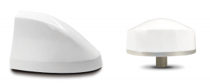
Vehicle Antennas
Designed for Intelligent connected cars and trucks
Photo: Harxon
Two new GNSS antennas are designed for vehicles equipped with advanced sensors, controllers, actuators and other devices. They are enabled for intelligent information exchanges between the vehicle and everything (V2X), connecting autos with GNSS, 5G, Wi-Fi, ultra-wideband and more. The integrated antennas support dedicated short-range (DSRC) and cellular vehicle-to-everything (C-V2X) communication, embedding a premium GNSS antenna with high gain for consistent and reliable precise positioning service. They also allow for multiple input and output of data to achieve swift internet download speed in 5G networks.
Harxon, harxon.com
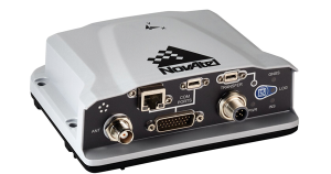
NVIDIA AV Support
Receiver now supported on autonomous platform
Photo: NovAtel
The PwrPak7-E1 GNSS receiver is now supported on the NVIDIA Drive Hyperion autonomous vehicle (AV) development platform. Selected for its robustness and precise position output, the PwrPak7-E1 will be offered with NVIDIA’s autonomous driving test fleets worldwide. Drive Hyperion is a fully operational, production-validated and open AV platform that reduces the time and cost required to outfit vehicles with autonomous driving and artificial intelligence (AI) features. The PwrPak7-E1 also is now compatible with NVIDIA’s DriveWorks v4 software release.
Hexagon | NovAtel, novatel.com
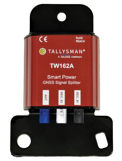
Splitter
Provides signals to two GNSS receivers
Photo: Tallysman
The TW162A automotive-grade smart power GNSS signal splitter supports the full GNSS spectrum: GPS/QZSS-L1/L2/L5, QZSS-L6, GLONASS-G1/G2/G3, Galileo-E1/E5a/E5b/E6, BeiDou-B1/B2/B2a/B3 and L-band correction service frequency band. It offers fail-over and fault-identification features. The splitter accepts power from all attached GNSS receivers; if one receiver fails, the next attached receiver automatically provides power to the splitter and antenna. If the antenna fails and does not draw current, all connected receivers will sense a current draw lower than 1 mA, indicating an antenna fault. The TW162A offers high performance in terms of noise figure, isolation and linearity.
Tallysman, tallysman.com
ADS-B Receiver
Enhances airport situational awareness
Photo: uAvionix
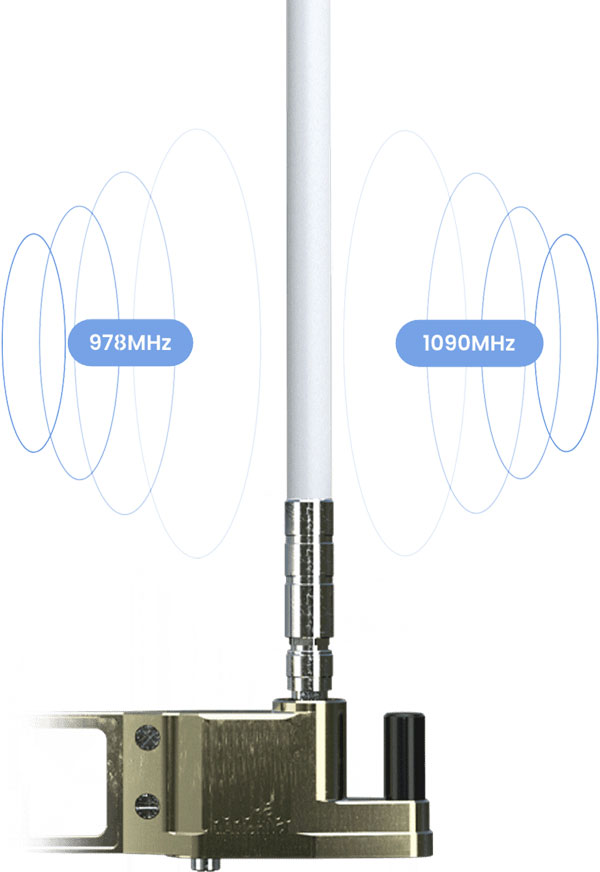
The pingStation 3 integrates 978 MHz and 1090 MHz ADS-B receivers, a GPS receiver, an antenna and a power-over-Ethernet (POE) interface into an easy-to-install, rugged weatherproof enclosure. With a selection of non-proprietary and industry-standard data interfaces, such as JSON and ASTERIX CAT 021, pingStation 3 is designed to integrate into a multitude of end-user applications, including airport displays, UAS Ground Control Stations (GCS), Unmanned Traffic Management (UTM) Solutions, and Flight Information Displays (FID). When paired with the VTU-20 airport vehicle ADS-B transmitter, pingStation 3 improves the situational awareness of ATCs and the safety of airport operations by reducing the risk of runway incursions.
uAvionix, uavionix.com
UAV
Defense UAS
Flexible UAV and control software combined
Photo: Ascent AeroSystems
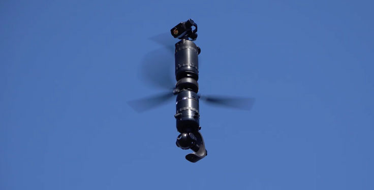
Ascent AeroSystems’ Spirit coaxial unmanned aerial system (UAS) offers a versatile and durable system for mission-critical operations. With a modular, plug-and-play payload design, the Spirit’s open architecture allows operators to add or upgrade software to unlock new operating capabilities without the need to design or develop a new aircraft. Autonodyne’s additive software solution allows the Spirit to perform autonomous tasks either individually or as a team with multiple vehicles, from a single operator and control station.
Ascent AeroSystems, ascentaerosystems.com
Autonodyne, autonodyne.com
Evaluation Kits
Now include mosaic Septentrio modules
Photo: ArduSimple
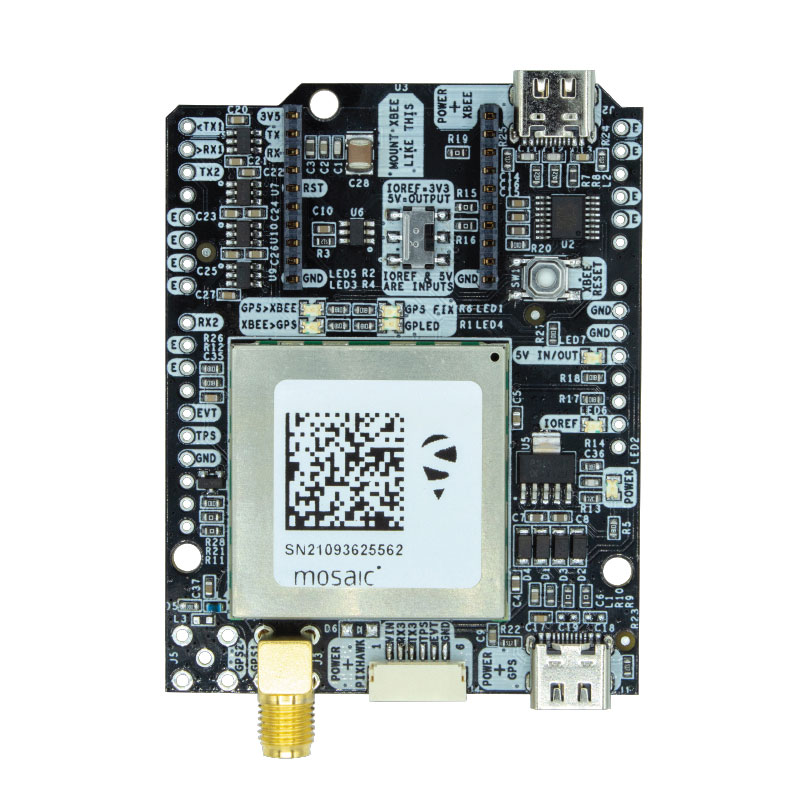
Two Septentrio modules are being integrated into ArduSimple’s new evaluation kits — the mosaic-X5 GNSS module and the mosaic-H heading module. The new kits make resilient centimeter-level positioning easily accessible for testing and prototyping. ArduSimple’s kits provide triple-band real-time kinematic (RTK) GPS/GNSS as a plug-and-play solution for the most popular development platforms such as Arduino, STM Nucleo, Raspberry Pi, Ardupilot and Nvidia Jetson. It enables developers of robotics, UAVs and autonomous systems to try out mosaic, a unique module offering the latest high-performance GNSS positioning technology.
Septentrio, septentrio.com; ArduSimple, ardusimple.com
Geospatial Data
Drones as a service
Photo: Beagle
A drone network solution offers on-demand imagery to customers in Germany at resolutions up to 50 times higher than available from commercial satellite data providers. The Beagle M drone and sensors can deliver image data at 1-cm per pixel many times faster than satellites and regardless of cloud coverage. The company’s charging hangars enable quick flights. After completing an autonomous inspection flight (up to 200 km on a single charge), the drone returns to its hangar where it charges for its next mission. The drone takes just 90 minutes to become fully charged, and can then advance to its next mission without any physical contact between operator and aircraft.
Beagle Systems, beaglesystems.com
Hexagon | NovAtel has updated its GPS Anti-Jam Technology (GAJT) portfolio with the new GAJT-710 product line, which features several enhancements over the previous generation.
The GAJT-710 product line is the next evolution of NovAtel’s battle-proven anti-jam technology for land and marine platforms. The new jammer direction-finding capability of GAJT enables situational awareness and a new silent mode feature reduces its thermal signature. These improvements, including enhanced GNSS tracking performance, are achieved while maintaining the same form and fit of the previous generation product.
GAJT units are deployed worldwide, providing anti-jam protection on land, at sea and in the air. Across these environments, GAJT protects GNSS navigation and precise timing receivers from the growing threats of intentional jamming and unintentional interference. GAJT reliably provides APNT for allied forces no matter the scenario.
“NovAtel has proven itself as a leader for assured PNT through our GAJT portfolio,” said Steve Duncombe, executive vice president of aerospace and defense at Hexagon’s Autonomy & Positioning division. “The new GAJT-710 builds on that success by providing new features combined with existing mission-proven technology to continue providing evolutionary APNT capabilities for the warfighter, national infrastructure and other mission-critical applications.”
NovAtel’s commitment to APNT is central to its product design approach. Deep GNSS expertise and lean manufacturing capabilities enable the delivery of high-performance products like the GAJT-710 in large volumes with minimal production and delivery times, the company said.
The GAJT-710 product line is available for land vehicles, marine vessels, positioning networks and timing infrastructure.
A strategic alliance announced on Dec. 15 between Orolia and Satelles includes product development and go-to-market activities of positioning, navigation and timing (PNT) solutions provided by the Iridium satellite constellation, independent of GPS/GNSS signals. The companies intend to provide PNT solutions to military, defense, government and commercial customers worldwide.
Orolia, the parent of GNSS-active companies Spectracom and Spectratime, among others, announced that it has formed a strategic alliance, including an equity investment with Satelles Inc. to develop, market and sell PNT solutions based on Satelles’ satellite time and location (STL) signal technology. STL is a unique space-based PNT technology that provides location and timing data independent from traditional GPS and other GNSS satellite signals. By using STL, Orolia’s Spectracom and McMurdo solutions will, according to the company, be less susceptible to vulnerabilities such as spoofing, interference and jamming that are associated with GPS/GNSS.
Iridium satellite, courtesy Iridium.
Based on the low-Earth orbit (LEO) Iridium satellite constellation, STL signals are up to 1,000 times stronger than GPS/GNSS; this signal strength, due in part to the constellation’s closer proximity to users, helps to prevent jamming and enables signal reach into buildings and other difficult locations. STL’s additional cryptographic security also ensures performance, productivity and security.
Projected key applications and use cases include energy/utility grids, enterprise data networks including financial systems, maritime/aviation navigation, fleet/asset tracking management, search and rescue and data center management. Further details on planned projects and products of the Orolia-Satelles partnership will be posted to this site in a follow-up story in coming days.
Many highly sensitive military, defense, government and commercial applications and operations require accurate and reliable PNT data. Today, these applications rely on signals from GPS/GNSS satellites. There are instances, however, where GPS/GNSS signal strength and security are not sufficient and prone to signal disruption. For these cases, the companies jointly state, STL can be used as a secure signal of opportunity to complement GPS/GNSS, making the applications more accurate and secure and less prone to interference and attack.
“In today’s increasingly dynamic and mobile world, there is a growing need for precise and robust positioning, navigation and timing information especially in business-critical, high risk and life-saving operations,” said Jean-Yves Courtois, Orolia CEO. “By augmenting Orolia’s market-leading GPS/GNSS-based solutions with Satelles’ STL technology, we will have the industry’s first essentially fail-safe, resilient PNT solution. This breakthrough offering will be ideal for mission critical applications in which the smallest of discrepancies in PNT data accuracy, availability and stability can result in a network outage, a system crash or a loss of life.”
“Satelles’ pioneering role in STL technology is a perfect fit with Orolia’s proven Resilient PNT strategy,” said Michael O’Connor, Satelles CEO. “We look forward to working together to introduce new products and solutions that will provide our customers with the utmost confidence that their positioning, navigation and timing data is accurate, secure and accessible.”
A fully autonomous, unmanned aerial vehicle (UAV)-based system for locating GPS jammers, currently under development, seeks to localize a jammer to within 30 meters in less than 15 minutes in an area comparable to that of an airport. Ultimately, the design team targets the ability to locate multiple, simultaneous jammers, and navigate in intermittent GPS and GPS-denied environments using a combination of GPS and alternate navigation aids. The system should be inexpensive and built from commercially available or open-source parts and software.
By James Spicer, Adrien Perkins, Louis Dressel, Mark James, Yu-Hsuan Chen, Sherman Lo , David S. De Lorenzo and Per Enge, Stanford University
The aviation community worries about GPS jamming. Recently, it struggled to find so-called personal privacy devices on Newark’s Liberty International Airport and traveling the nearby New Jersey Turnpike.
A number of unintentional jamming incidents took a long time to resolve. The disruption from an intentional, malicious jamming attack could be far worse. Airport authorities should be prepared to locate and shut down a coordinated attack by numerous jammers capable of disrupting the GPS service over an entire airport.
The closure of a major airport for the many hours or days it would take to locate even a couple of backpack-sized transmitters would be not only be highly disruptive in flights delayed or diverted, it would negatively impact the confidence of the flying public.
Any system in place to mitigate this threat must be inexpensive enough to be deployed at least at the nation’s major commercial airports, autonomous enough to be operable with limited training and certification, and rapid and accurate enough that a jammer can be routinely apprehended by ground-based law enforcement. It must be able to navigate successfully in GPS-denied environments using alternative position, navigation and timing (APNT), and have the range and capacity to search an airport-sized area as well as the approach corridor leading to runway touchdown.
This article describes such a system and device presently in research and development: the Jammer Acquisition with GPS Exploration & Reconnaissance (JAGER).
Vehicle Design and Operation
The JAGER UAV is a based on a commercially available, multi-rotor airframe modified to suit the mission specifications. The 1.2-meter diameter octocopter has a maximum takeoff weight of 11 kilograms (24.2 pounds), a top speed of 20 meters/second (m/s, 45 mph), and can fly unloaded for up to 30 minutes.
We have replaced the battery tray with our own carbon fiber design that allows us to carry 16 Ah of lithium polymer batteries for a maximum power draw of 4 kW. This extra capacity means that even with a 5-kilo experimental payload, the present craft can remain aloft for up to 15 minutes without recharging.
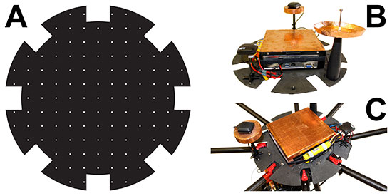
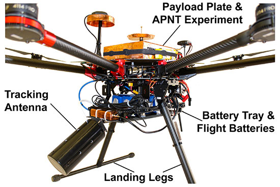
The payload plates are also custom-made from carbon fiber, and it is to these that the UAV’s experimental payloads are mounted (see FIGURES 1 and 2). One payload plate is flown at a time, and is secured on top of the airframe with a quick-release mechanism. This modularity allows for individual experiments to be mounted to their own payload plate and ground-tested before being secured to the UAV. Different experiments can be switched out rapidly for efficient use of battery capacity and flight time.
Figure 1. (A) Diagram of the payload plate showing regularly spaced mounting holes. (B) Plate with APNT experiment mounted. (C) Payload plate / experiment assembly secured atop JAGER UAV.Figure 2. Image of the vehicle showing the battery tray slung beneath the central body, the APNT experiment and payload plate secured on top, and the jammer-hunting antenna mounted at the front.
The plate itself also offers flexibility for component mounting. Regularly spaced, threaded holes across the plate mean components’ positions can be easily changed to find an optimal configuration. This can be particularly useful for minimizing interference between computers and noise-sensitive components such as antennas and magnetometers.
Software. We modified existing, open-source autopilot software to fly the mission. The craft is fully capable of completing a mission autonomously, but also can be taken over by a human pilot if necessary. A ground station also can be used to send commands to the octocopter, but is primarily used to monitor UAV location, battery life, and jammer belief state.
The autopilot software also has been adapted to communicate with various vehicle payloads. Experiments using APNT equipment, for example, pass their data to the autopilot, which will combine these signals with its own GPS data for accurate navigation in areas where the GPS signal might be intermittent or unreliable. In return, the autopilot can be used to pass data to experiments reliant on altitude, attitude, atmospheric pressure or location information.
The ground station monitors instruments’ data and status in real time. This not only allows for control of airborne experiments, but also straightforward ground testing. Synthetic autopilot data can be fed to an experiment to ensure that all systems are performing correctly before they are mounted on the vehicle for flight tests.
APNT Overview
Key to navigating in a GPS-denied environment is the use of signals from APNT networks for location determination. The proposed system should be able to navigate using any or all available APNT signals, and should weight each one according to its strength and reliability in order to formulate the most accurate estimate of both its own and the jammer’s position.
Here we describe the use of the universal access transceiver (UAT) and distance measuring equipment (DME) network for our APNT signals. The UAT signal has been implemented by the Federal Aviation Administration (FAA) in the United States as part of automatic dependent surveillance–broadcast (ADS-B), and is transmitted through a network of terrestrial ground stations.
The ADS-B network was only completed across the contiguous United States in 2014, so it is new compared to established cellphone networks. It is more comprehensive than many other terrestrial systems, so that coverage of most airports is guaranteed. While GPS reception requires an unobstructed view of the sky, UAT reception requires a direct line of sight to a transmitting tower. However, the flatness of terrain surrounding most airports as well as the UAV’s airborne vantage point ensures that UAT signals will probably be visible throughout most jammer-seeking missions.
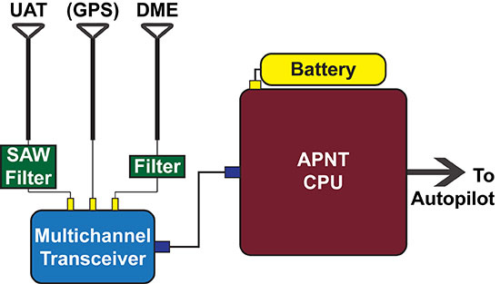
The APNT equipment used for navigation by the JAGER UAV consists of UAT (978 MHz), DME (982 to 1213 MHz), and GPS (1575.4 MHz) antennas, a multichannel transceiver to combine the two signals, and a computer for data processing (see FIGURE 3). A dedicated lithium-ion battery powers the entire APNT payload. The current system does incorporate GPS to estimate the time offset, but future iterations of the system will derive time from sources other than GNSS so that true GPS-denied navigation is possible.
Figure 3. Schematic of the APNT configuration on board the JAGER UAV. Resulting location information is passed to the autopilot for navigation.
The UAT antenna receives multiple signals from visible ADS-B ground station transmitters. The transceiver combines these with a GPS timestamp, and the data is passed to the APNT computer for analysis. Based on knowledge of the absolute locations of the ADS-B antennas, the range of the vehicle from each antenna can be calculated, which in turn can be used to trilaterate the vehicle’s absolute position. This position is then passed to the autopilot for the UAV’s navigation, while the status of the equipment and signal strength are passed down to the ground for monitoring in real-time.
The necessity of using GPS signals as an accurate timing system is a current limitation, as navigation in GPS-denied conditions is clearly not possible while we are using GPS as a clock. As mentioned eariler, future designs will derive time from non-GNSS sources, such as chip-scale atomic clocks or the terrestrial ranging signals.
Carrying an onboard computer allows for real-time processing of the terrestrial alternative navigation signals. However, there are a few limitations to the use of these signals. First, the vertical position is difficult to calculate due to the geometry of terrestrial signals as well as the sparsity of visible station at low elevation. This is solved by using a baro-altimeter. Second, DME signals do not provide a pseudoranging function. Current work sponsored by the FAA is developing a DME pseudoranging capability. As the technology matures, we will improve the hardware and algorithm that can be integrated into future JAGER designs, resulting in lower weight and power overhead for the APNT payload.
Tracking Overview
GPS jammers do little more than emit signals in the GPS frequency range. Because the signals from GPS satellites are so weak by the time they reach the Earth, ground-based jammers do not have to be especially powerful to overwhelm GPS in their immediate vicinity. A jammer is no more than a ground-based radio-frequency source radiating within the GPS spectrum.
The JAGER system will autonomously locate the nearest beacon emitting electromagnetic signals at the target frequency: the GPS frequency in this scenario. Testing such a system is difficult due to the illegality of jamming the GPS signal within the United States. We instead test the system using a powerful Wi-Fi beacon as a proxy for the overpowering jammer. Excepting the target frequency, the procedure to locate the jammer is identical to the GPS case.
To receive the jamming signal, the front of the craft carries an antenna optimized to receive signals of the target wavelength; the current antenna has a 60° cone of maximum sensitivity. It is angled downward 30° from the horizontal, so that the craft can receive all signals from the horizon to 30° from vertical. This gives the UAV visibility over most of the space in front and underneath it. Like the other payload equipment on the vehicle, the antenna is secured with a fast-release mechanism so that it can be easily swapped out if necessary. For Wi-Fi tracking, we use a Yagi antenna with 60° beamwidth and 9 dBi gain. In upcoming trials, we will test different antenna configurations (such as dual antennas, small antenna arrays, and directional antennas augmented with omni-directional antennas) to determine benefits of these different layouts.
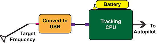
Signals from the antenna are passed into a module that converts the Wi-Fi data to serial, then from serial to USB. A single-board Linux computer with a quad-core processor then analyzes the signal data (see FIGURE 4). The hardware used to locate the jammer weighs 160 grams, so has negligible impact on the vehicle’s flight time or range.
Figure 4. Schematic of the tracking system on board the JAGER UAV. The resulting believed location of the target is passed to the autopilot.
To find the jammer’s location, the UAV performs a controlled yaw spin while recording the strength of the jamming signal. On the basis of the signal landscape surrounding the vehicle, the computer estimates the jammer’s location and sends a message to the autopilot instructing the craft to fly in that direction (or, more accurately, in a direction that optimally improves the ability of JAGER to find the jammer quickly). In return, the autopilot updates the tracking computer and ground station as to the vehicle’s position.
After moving a certain distance towards the jammer’s believed location, the craft repeats the spinning maneuver and starts the process again. Although rotating only the antenna might increase the speed of the operation, the energy required to carry the necessary antenna-rotation mechanisms for the duration of a flight is more than that needed to spin the entire craft.
The tracking algorithm is not as straightforward as gradient ascent or homing, and the vehicle will not always fly in the direction of greatest signal strength. The operational area is uneven, and may include buildings, towers, or airplanes, resulting in a complicated RF environment. Signals are scattered, diffracted and reflected, meaning that an algorithm that simply follows the strongest signal will not always converge on the actual jammer location.
To decide the optimal path from the vehicle’s present location to the jammer’s believed position, the tracking algorithm makes use of partially observable Markov decision processes (POMDPs). POMDPs model decision processes where the underlying state of the system (that is, the location of the jammer) is never completely known, and maintain a probability distribution over the set of all possible states.
The entire deployment area (an airport and its environs, for example) is split up into a square grid. For every possible combination of jammer and vehicle grid square locations, the signal strength and direction that would result is calculated offline prior to deployment and stored in a database on the tracking computer.
During the mission, the UAV records its own position and the sensed jamming signal’s strength and direction. The jammer location that would correspond to this result is retrieved from the database, as well as a measure of the strength of this belief state.
Once the craft has a belief as to the location of the jammer, it moves to a new location in the jammer’s believed direction before taking another measurement of signal strength. The new location and new measurement are combined, and the updated corresponding jammer location is retrieved from the database. This process is repeated until the vehicle believes itself to be right above the jammer, at which point a photograph is taken, the ground station is notified, and the hunting mission is complete.
Having found the jammer, the system can be programmed to execute a wide range of operations. These include reporting coordinates and a live image of the believed jammer location back to the ground station, hovering above and tracking the jammer if it begins to move, landing at the jammer site, or returning to base.
We calculate and store the POMDP decisions in advance of the flight. This strategy has some advantages. First, it allows for almost instantaneous decision-making. This is because the algorithm’s decisions are based solely on the vehicle’s current location and sensory observations and not on any previous states (a defining characteristic of a Markov decision process). The craft needs only to observe its current state in order to look up its next move in the database. This enables rapid tracking in flight.
A second advantage is that safety checks can be pre-programmed into the database in advance of deployment. While JAGER is programmed to move towards the grid square believed to contain the jammer, it can also be programmed to avoid or take special precautions when moving towards or in the vicinity of certain squares in the grid (also called geo-fencing). In an airport situation, for example, the vehicle would avoid moving into the square containing a control tower or ground-based antenna, or would fly at a minimum altitude over buildings and taxiways to avoid collisions.
Finally, the integration between the autopilot and the tracking software can provide other important safeguards: in the proof-of-concept system, any navigation decision taken by the software can be relayed to the ground for human verification before the UAV begins to move. This supervised mode of operation lends itself to a seamless migration path to fully autonomous operation (always overseen by a human operator).
However, one disadvantage of calculating and storing decisions in advance is the storage space needed on the vehicle. Because the result of every possible combination of vehicle and jammer locations within the grid is calculated, the size of the database grows quickly with increasing numbers of possible positions (and states). The larger the grid or the greater the required accuracy, the more space is needed to store the database. With current algorithms, the database needed to locate a jammer to within 30 meters in an area the size of an airport requires 15 gigabytes of storage space, resulting in longer lookup times during flight.
We are considering several strategies to mitigate this disadvantage, including better compression, more effective search algorithms, and uploading from a ground server only the parts of the database that correspond to the vehicle’s current operational area. Another strategy is to use an adaptive mesh that changes in resolution depending on the jammer’s belief state: at low certainty the database resolution is low, but increases in the appropriate area as the jammer’s location becomes more certain.
Another disadvantage of pre-solving the decision-making process is that the system must be reconfigured for every site in which it is deployed. The specifications of the tracking algorithm will change depending on the requirements of the operating area. The grid size, shape and absolute location must change to suit the area being protected. The resolution of the grid depends on the required accuracy of the tracking system, and restricted or prohibited locations must suit the terrain, buildings and geological features of the deployment space. For example, a lead JAGER vehicle could be adapted and tested to suit a particular airport, and then the bespoke algorithm and database uploaded to backup vehicles in that airport’s fleet.
APNT Performance
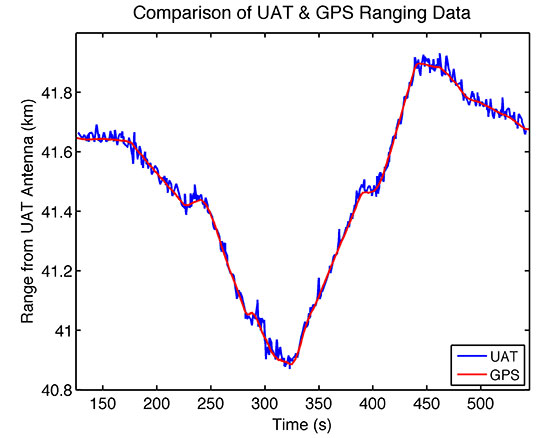
During the Joint Interagency Field Experimentation (JIFX) event at Camp Roberts, California, in November 2014, we tested the APNT system by deploying the vehicle with GPS, UAT and DME antennas simultaneously recording data. GPS receivers on the ground were used to collect reference measurements to estimate the time of transmission of the signals from the APNT sites. All signals were recorded at an altitude of 275 meters above ground level (600 meters above sea level), at four different points roughly 800 meters apart, and the data analyzed for comparison. As expected, the UAT broadcast was noisier than the GPS signal. However, it was possible to calculate a range from the UAT data that was accurate to within 16.6 meters of the GPS reference position, well within the 30 meters error bound specified in the project specification (see FIGURE 5).
Figure 5. UAT range deviates from GPS derived range-estimate by an average of only 16.6 meters throughout the duration of the test flight.
While UAV navigation using APNT was done offline in post-processing for these tests, with planned algorithm improvements and hardware acceleration the UAT signal can be used to get real-time position information nearly as accurate as that from GPS. Thus the JAGER UAV can be navigated with comparable reliability in both GPS and GPS-denied environments.
Terrestrial APNT signals will be received at a wide range of power levels. This effect is not observed with the GPS network, as the different satellite signals are broadcast from such a great distance that any differences in received signal strength are relatively small by the time they reach Earth. For terrestrial networks, signals from transmitters close to the receiver can be many times stronger than those further away, which can result in two issues: 1) interference where one signal overwhelms another, and 2) inability to process a signal if the receiver does not have adequate dynamic range to capture strong and weak signals clearly.
This problem was observed in our tests, as we were receiving two signals: one 13.7 kilometers (DME) and the other 43.5 kilometers (ADS-B UAT) from our test site. Calculating accurate ranging estimates from the two required determining a gain setting that had dynamic range adequate for receiving both signals clearly.
Vehicle Performance
During experimental testing, the vehicle itself also underwent rigorous assessment of its performance under different conditions. Due to the delicate and often expensive nature of the payloads and experiments made possible by the JAGER platform, it is essential that the vehicle perform as expected, and that there are multiple procedures in place to protect the payloads in case of vehicle failure.
Because the open-source autopilot had never been used with such a large vehicle, we first ground-tested the craft’s flight control and stability. The vehicle was tethered and constrained to move in only one axis, and ropes were used to control its roll. While altering autopilot variables controlling roll and pitch feedback loops, we measured the vehicle’s response to impulsive disturbances and the time taken for it to right itself when upset. In this way we could tune the control gains and verify that the vehicle would be exceptionally stable during flight in even the most challenging atmospheric conditions. While we preferred to fly in the early morning hours to exploit clear air and lower winds, we did perform tests with momentary gusts of up to 7 m/s during envelope expansion flights.
We tested the vehicle with two accelerometers on board to measure how the rotors’ vibrations affected the rest of the craft. One accelerometer was attached to the airframe itself, while the other was secured to the payload plate. A comparison of the acceleration data recorded by the two instruments revealed that the payload plate experienced significantly less vibration than the airframe during flight, and both measurements remained well within the tolerances advised by the airframe manufacturer.
Two crucial flight modes also were tested before payloads were flown on the vehicle. Both altitude-control mode and position-control mode were tested to ensure that they could precisely constrain respectively the vehicle’s altitude and absolute position in a range of atmospheric conditions. Results showed that in altitude control mode, the vehicle’s z-coordinate was held constant to within ± 0.5 meters. In position control mode, its x- and y-coordinates remained within ± 1.0 meters (or a single vehicle length).
The success of the JAGER tracking mission also depends on accurate position measurements from the UAV. Operators must be confident in the vehicle’s position, so that ground forces can easily apprehend the located jammer, and also so that there is confidence in the success of safety protocols including geo-fencing, no-fly zones and minimum flight altitudes.
In addition to the geo-fencing and flight precautions taken by the tracking algorithm, the JAGER UAV has several other safety procedures executed automatically by the autopilot. A non-catastrophic error in the flight systems or payload is transmitted to the ground station for human troubleshooting, and commands can be sent to the vehicle as to how to proceed.
Finally, should we continue operations and allow its batteries to get sufficiently low, the vehicle will automatically return to launch site for landing and battery replacement. A catastrophic failure such as the loss of a motor will result in an immediate controlled landing. The craft can also be commanded from the ground station to land or return to launch, and can be taken over by a human pilot at any time.
Other tests verified that the vehicle has the range and endurance to be successful when deployed in an airport setting. When fully loaded with APNT and tracking payloads, the UAV exhibited a top speed of 10 m/s, enough to cover the length of an A380-capable runway in less than 5 minutes. A 20-minute flight endurance means that even including hovering during jamming signal observations by the tracking antenna, the JAGER system can hunt easily and effectively throughout an airport-sized area. Furthermore, we continue to explore techniques to improve dash capability, including reducing the weight of the APNT payload, and we anticipate describing results of these efforts in future reports.
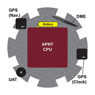
Electromagnetic Interference
Because of the payload tray’s small area (0.5 m2), electromagnetic interference (EMI) between APNT components was a significant issue during testing. The GPS and UAT receivers are extremely sensitive to interference from other sources emitting in the frequency ranges to which they are tuned. The APNT computer, by contrast, is composed of various processors, clocks, drives and power boards that emit powerful electromagnetic noise at a wide range of frequencies as a byproduct of their normal operation.
The size and mass of the APNT computer board meant that it had to be mounted in the center of the payload tray to avoid unbalancing the UAV. That left a maximum 7 centimeters of space around the computer on which to mount the two antennas (see FIGURE 6). With no shielding, the EMI from the computer proved powerful enough to completely overwhelm the GPS, UAT and DME network signals, making navigation and position estimation using any network impossible.
Figure 6. Diagram showing the APNT experimental payload, and the proximity of the EMI-radiating CPU to numerous antennas.
The EMI problem was solved in three ways. Masts were used to raise the receiving antennas to a height of 19 centimeters above the payload tray, the maximum height at which a mast collapse wouldn’t cause catastrophic rotor and vehicle failure.
The antennas also were moved around the edge of the payload tray so as to be furthest from the system components radiating at their particular frequency. Two devices that proved particularly problematic were the solid-state hard drive in the CPU and the telemetry radio antenna, which radiated EMI that interfered with the GPS and UAT frequencies respectively. This was solved by moving the telemetry antenna to the underside of the craft, and the GPS antenna to the far side of the payload plate from the hard drive. The flexible design of the payload plate described earlier ensured that the relocation and testing of components was a straightforward process.
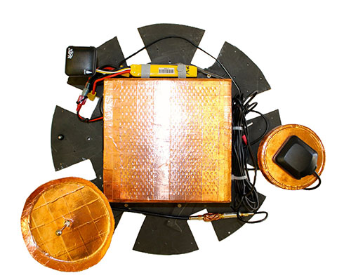
Shielding, however, proved to be the most important factor in eliminating EMI. Custom-made copper shields were added to the two masts to shield the antennas from the computer below them while still allowing an unobstructed view of the sky (see PHOTO). We tested numerous shielding iterations, including wire meshes and aluminum and lead foils; however; all were ineffective due to the strength and wide range of EMI wavelengths emitted. Finally, the computer itself was covered in a 2-millimeter layer of copper and 1-millimeter steel sheet. This combination struck the best balance between effectiveness and weight: aluminum was light but proved ineffective at shielding, while lead was very effective at EMI shielding but was too heavy for the UAV to carry.
The APNT payload prior to installation of the DME antenna. The copper shielding on the CPU and antennas can be clearly seen.
Conclusions
The development of the JAGER system contributes to U.S. preparation for a GPS jamming attack on civil aviation. While the first iteration described here is a significant improvement on previous jammer-hunting systems, future iterations of the JAGER UAV will be able to successfully navigate in a GPS-denied environment using alternative navigation signals including UAT and DME, and broadcast an accurate estimate of their position down to the ground.
The use of an octocopter flight system gives speed, maneuverability and sensory perception that far exceed any ground-based tracking effort. A fully loaded top speed of 10 m/s and almost instantaneous direction changes allow for efficient hunting over an airport-sized area and the location of a GPS jammer to within 30 meters, within a 20-minute flight endurance.
As the JAGER system can be entirely assembled from commercially available or open-source components and operates entirely autonomously, the system provides a low-cost, readily obtainable solution to the problem of GPS jamming. This means that it can be deployed quickly and is operable without extensive prior training.
The integration of autopilot, APNT navigation and tracking systems also allows for comprehensive monitoring and control of the UAV from the ground. Telemetry and data links to the ground station provide real-time updates as to the craft’s position, the jammer’s believed location and the status of all systems and instruments running on the vehicle. Safety protocols implemented in the software ensure that there is no risk of collision with site buildings, vehicles or personnel.
JAGER’s modular design gives operators extensive flexibility in situations that are capable of being successfully resolved by the system. The switching of equipment and software to allow the UAV to use GPS navigation to hunt a UAT or DME jammer, for example, could be effected in a matter of seconds.
The JAGER system also provides a reliable test platform for any experiment that requires airborne operation. The exceptional stability of the airframe combined with extended flight time, high top speeds and pinpoint positioning lends the system to a wide variety of applications beyond jammer tracking, including network monitoring, atmospheric experiments and biological research.
Manufacturers
The JAGER UAV airframe is a S1000 octocopter by DJI Innovations, Shenzhen, China; the flight batteries are a 8000 mAh model by Hextronik, Dongguan, China; the autopilot hardware and GPS antenna is a Pixhawk by 3D Robotics, Inc., San Diego, California; the autopilot software is based on PX4 by Pixhawk.org. The JAGER navigation GPS is made by u-blox, and the receiver for the APNT clock is made by Trimble. The UAT hardware includes an ASR-2300 multichannel transceiver by Loctronix Corporation, Woodinville, Washington; the tracking hardware comprises a 2.4 GHz Yagi antenna from L-com, North Andover, Massachusetts; an RN-XV Wi-Fi module by Roving Networks, Chandler, Arizona; and an Odroid-U3 computer by Hardkernel Co., Gyeonggi, South Korea.
James Spicer is pursuing concurrent bachelor’s and master’s degrees in aeronautics and astronautics at Stanford University.
Adrien Perkins is a Ph.D. candidate in aeronautics and astronautics at the Stanford University GPS Laboratory. He received his undergraduate degree in mechanical aerospace engineering at Rutgers University.
Louis Dressel is a graduate student at Stanford University. He received his undergraduate degree in aerospace engineering from Georgia Tech, with a minor in computer science.
Mark James is a master’s student in aeronautics and astronautics at Stanford University.
Yu-Hsuan Chen is a research associate at the Stanford GPS Laboratory. He received his Ph.D. in electrical engineering from National Cheng Kung University, Taiwan.
Sherman Lo is a senior research engineer at the Stanford GPS Laboratory.
David S. De Lorenzo is a principal research engineer at Polaris Wireless and a consulting research associate to the Stanford GPS Laboratory.
Per Enge is a professor of aeronautics and astronautics at Stanford University, where he is the Vance D. and Arlene C. Coffman Professor in the School of Engineering. He directs the Stanford GPS Laboratory.