In the next two to four years, mobile device location platforms will be able to provide positioning performance that enables emergency call (E911) and location-based services (LBS) with excellent accuracy (5–10 meters) in all locations. We call this accurate everywhere location, and it will be a significant enabler of indoor navigation applications and for even wider adoption of consumer LBS.
In fact, we may eventually forget how we ever lived without it. This technology can enhance our lives by enabling our mobile devices to know precisely where we are at all times. Armed with this information, our devices can behave in a way that suits our specific situation, and they can do this without us having to do anything other than keep the phone with us.
Text and images will get significantly bigger while driving or walking. Facebook notifications can be automatically disabled while at work. Shopping lists can be automatically displayed when approaching a store that has an item on the list. The potential benefits are endless — provided that the privacy issues associated with location are handled appropriately.
GNSS is the superior technology when a mostly unobstructed sky is available, but it can’t deliver accurate position fixes in all environments — at least not at a cost and in a form factor that works for consumer mobile devices. Accurate everywhere location requires some form of advanced hybrid location technology. Because its definition is constantly evolving, the term hybrid can mean different things to different people. This article aims to clear that up.
Here is an overview of the hybrid positioning technology currently used in mobile devices, as well as what is coming in the next two to four years that will enable accurate everywhere location:
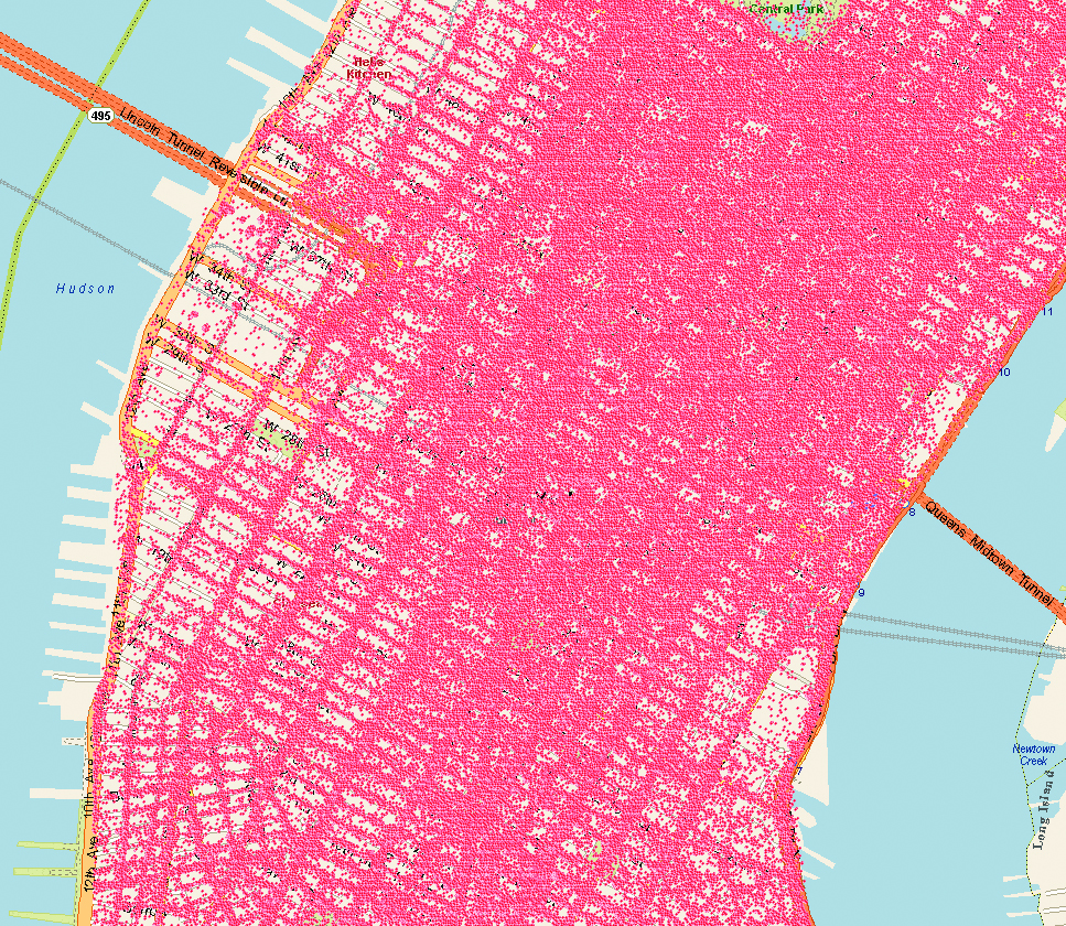
GPS + GLONASS. Multiple GNSS technologies are starting to be more common in new chipsets aimed at mobile devices, and assisted-GPS (A-GPS) + A-GLONASS is right around the corner. The benefit from this hybrid GNSS approach is that with more satellites in the sky, devices are likely to receive more line-of-sight signals in challenging environments where a significant portion of the sky is obstructed (like urban canyons). While this might improve performance on a street in downtown Manhattan, it does not help when you are in the middle of a building or in the subway.
Cellular Multilateration + A-GNSS. Mobile devices with CDMA cellular radios have supported hybrid A-GPS + advanced forward-link trilateration (AFLT) for more than a decade. This concept is now being applied to long-term evolution (LTE) devices, with support for A-GNSS + observed time difference of arrival (OTDOA) being written into the 3GPP standards. Both AFLT and OTDOA are forms of cellular multilateration, which means that devices can make measurements of relative timing offsets between multiple downlink cellular signals, and those measurements can be used in a hyperbolic multilateration formula to compute a position (one signal acts as reference and hyperbolic intersection of 2+ signals are used for position).
Does this sound familiar? It happens to be very similar to GNSS location computation, so it is possible to combine measurements from cellular signals and measurements from GNSS satellites to compute a hybrid position. For example, 2 satellites + 2 cellular measurements can be combined to compute a position, which makes this technique very attractive. Although it is used for both E911 positioning in North America and LBS worldwide, this technology will become even more widespread as LTE adoption increases.
A-GNSS + Wi-Fi Positioning + eCID. Many popular smartphones today support Wi-Fi positioning and enhanced cell ID (eCID) in addition to A-GNSS. This hybrid solution allows coarse positioning in indoor environments where A-GNSS does not work. Solutions for Wi-Fi and eCID positioning are currently very fragmented and proprietary. However, this is the reason you are able to get a semi-accurate position fix on your Android or iOS mobile device when GNSS satellites are impossible to measure (many other devices support this as well). These technologies are going to provide more accurate information as time goes on, but we don’t believe they will achieve accurate everywhere location on their own.
A-GNSS + Wi-Fi Positioning + Cellular Positioning + Sensors. You might have guessed it, but we think accurate everywhere location will be enabled by a combination of all the above hybrid techniques plus one more important technology: sensors. Integrated sensors like accelerometers, magnetometers, and barometers enable devices to sense changes in direction, orientation, and elevation. Given an accurate starting location (for example, GNSS position fix), sensors can track location accurately for several minutes (and this will continue to get better). Location error will accumulate over time, but this can be minimized when Wi-Fi, cellular, and GNSS positioning are used in conjunction to constrain the error. Furthermore, barometers can be used to track elevation changes, thereby allowing devices to know exactly what floor of a building a user is on. Other technologies, or signals of opportunity, may be used in the future to further improve performance, but we think this mix of A-GNSS, Wi-Fi, cellular, and sensor positioning is the key to accurate everywhere location in mobile devices.
With substantial R&D dollars being spent now, and standardized testing for hybrid positioning emerging this year, our best estimate is that the accurate everywhere technology will become commercially widespread by 2015.
Brock Butler is director of Spirent’s Wireless Location Technologies, part of a team that has made major contributions to development of the LBS standards in the 3GPP: Spirent filled the editor and rapporteur roles for the TS 51.010 and TS 34.171 A-GPS Terminal Conformance Specifications, as well as the editor role for the Enabler Test Specification for SUPL in the OMA. Butler holds a BSc in electrical engineering from Villanova University.
By Dinesh Manandhar and Hideyuki Torimoto, GNSS Technologies, Inc. Japan
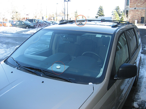
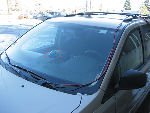
An indoor messaging system (IMES) has been developed to meet the challenges of indoor and deep indoor positioning, as a system that can be implemented in any device that has a GPS/GNSS receiver without hardware modification. IMES can provide reliable 3D position data with a single transmitter device without performing range calculation.
The cost of embedding location data in portable electronic devices is so low that universal penetration can be foreseen in the next five years. Roughly 70 percent of the world’s population now uses approximately five billion cell phones. This number has doubled in the last four years. Future growth is expected at the same or even a higher growth rate.
Due to the emergence of smart phones and location-based services (LBS), mobile phones are used not only for communications but also for many applications related to LBS, entertainment, and games. GPS/GNSS devices are included in mobile phones due to compulsory requirement of E911 and safety-and-rescue services by law in many countries for security and safety.
Access to map data and value-added services using these map data is getting cheaper and eventually will be freely available. Major service providers like Google, Nokia, and Apple already provide access free of cost, and they increasingly focus on location as a core business construct.
GPS/GNSS devices were designed to work outdoors, and most GNSS applications are limited to outdoor environments. However, GNSS reliability, availability, and accuracy have led to development of many new and innovative applications that are designed for use in both outdoors and indoors in a seamless fashion. Today, GNSS receivers are integrated in many other devices like mobile phones, navigation systems, personal navigation devices, game devices, security devices, and many LBS-related devices. These devices are increasingly used in indoor environments. Indeed, people generally spend much more time indoors than outdoors. Hence, it is extremely important to have a reliable system that can provide fairly accurate position data even in indoor and deep indoor locations.
Current GNSS systems do not provide solutions for indoor and deep indoor environment with reliable accuracy of 10–20 meters. New modernized signals such as L5 do provide better position accuracy and better signal reception in indoor areas, but achievable positioning will still vary, and will continue to require more than four visible satellites with some assist data — and still be limited to soft indoors environments such as rooms with glass windows or walls. Limitations remain for hard and deep indoor environments.
To surmount these obstacles and provide indoor navigation, various technologies such as pseudolites, assisted GPS, wireless networks (Wi-Fi), Bluetooth, RF tagging, and so on have been developed. However, these technologies have their own limitations and are not the most suitable tools for seamless positioning and navigation. Except for pseudolite and A-GPS, they are designed for communication, not for positioning or navigation purposes, but are used for navigation purposes since no other suitable technology exist.
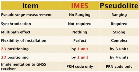
Pseudolite systems are currently in use for indoor positioning. While technically sound, a system needs at least four signal transmitting units. To cover a large area, it needs many transmitters suitably located and time-synchronized to one other, or their clock errors must be known. Pseudolite systems provide position data based on range calculation from the receiver to a number of transmitters, and this calculation is heavily affected by signal multipath. Table 1 compares IMES and pseudolites.
Table 1. Comparison between IMES and pseudolite.
A-GPS is widely used in mobile phones to compute position data. A-GPS technology includes high-sensitivity signal processing to acquire weak signals and external assistance of data like time, approximate position, and satellite-orbit related parameters. Provision of assistance data requires a communication link between the receiver and the data source, for example, the mobile phone network itself. Thus, A-GPS will not be possible if there is no communication link.
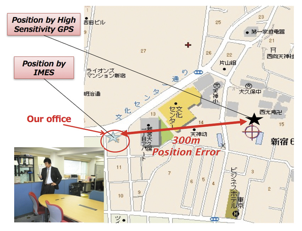
Normally, A-GPS provides 2D position data. The height data (if 3D output is available) will be highly erroneous. The accuracy of such position data varies from few tens of meters to few hundreds of meters. Also, the position data is heavily affected by signal multipath. Figure 2 compares IMES position and mobile phone position inside an office building. The A-GPS position error is about 300 meters in this case.
FIGURE 2. Indoor position from high-sensitivity GPS and IMES.
Wi-Fi is used for indoor positioning in many mobile phone devices. The phone provides position data from a built-in GPS receiver, a Wi-Fi device, cell ID, or a combination of any of these. Recently, position data from Wi-Fi has become popular for indoor as well as outdoor position, since Wi-Fi signals are so freely available. However, using these Wi-Fi signals requires registering the signal power and availability at reference locations. To do this, a huge number of Wi-Fi devices are registered driving around the city. Since these devices are basically installed for communication purposes, they can be relocated, removed, or new devices may be installed without any information to the users or service providers. Thus, continuous maintenance and updating of all these devices are necessary at certain time intervals. The coverage of Wi-Fi devices is not uniform and may vary widely from area to area, affecting position accuracy.
Telecom service providers are considering the possibilities of seamless positioning technologies. They would like to have one single device that can provide 3D position data both indoors and outdoors, without additional power or cost, and with satisfactory 3D position information. If such a seamless positioning technology is available, it will undoubtedly generate a huge global commercial market. The availability of such technology will also aid development of new applications in location-based services, advertising, marketing, entertainment, and gaming.
We have conducted research in indoor positioning for the past few years, beginning with pseudolite systems. We have developed IMES to meet the shortcomings of the technologies described earlier for indoor and deep indoor positioning. IMES for a seamless positioning environment can be implemented in any device that has a GPS/GNSS receiver, without hardware modification. IMES can provide satisfactory and reliable 3D position data with a single transmitter device without performing range calculation.
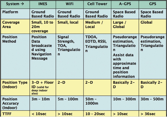
Table 2 compares IMES with other indoor-position capable devices. IMES can provide the same accuracy even in deep indoor locations, whereas cell tower, A-GPS, and GPS cannot work in such areas. All other systems except IMES provide only 2D position data indoors. The height data from A-GPS is very unreliable and hence cannot be used.
Table 2. Comparison of IMES with other indoor positioning systems.
IMES Concept
The main concept of IMES is to transmit position and floor ID of the transmitter with the same RF signal as GPS. IMES transmits latitude, longitude, height, and floor ID by replacing the ephemeris and clock data in the navigation mes
sage of GPS. A single unit of IMES is enough to get the position data, since the position itself is directly transmitted.
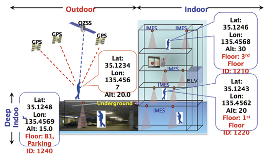
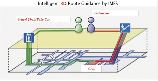
Figure 3 shows the concept of seamless position data using IMES, where the same receiver can be used both indoors and outdoors without interruption. GNSS satellites provide positioning and navigations outdoors, while IMES provides indoor navigation. Since the signal structures of GPS satellites and IMES is the same except for the navigation message contents, the same receiver can be used for both cases. Current GPS receivers will be capable of receiving IMES signals with modification of firmware only to decode the navigation message. Figure 3shows the concept of seamless 3D route guidance.
Figure 3. Seamless 3D route guidance using IMES.
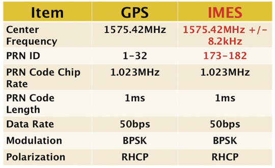
Signal Properties. The IMES signal is designed much like the GPS signal. It uses the same center frequency as GPS with an offset of +/– 8.2 kHz to minimize the possible interference from IMES to GPS signal. Ten PRN codes from 173 to 182 are assigned for IMES. These codes are provided by the U.S. government. Other signal-related parameters are the same as the GPS L1 C/A code signal. Table 3 shows IMES signal properties with respect to the GPS signal.
Table 3. IMES signal properties with respect to GPS.
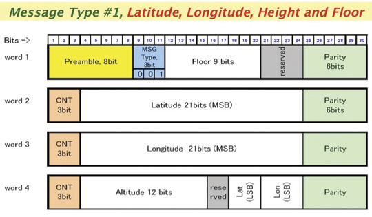
IMES has four different types of navigation message. The most significant is Type 1 as shown in Figure 4. It transmits latitude, longitude, height, and floor ID. The transmission of floor ID is a key factor for perfect 3D position data. Other message types are Type 0 (2-D position data with floor ID), Type 3 (short ID), and Type 4 (medium ID).
Figure 4. IMES Message type 1, 3D position, and floor
Interference Issue
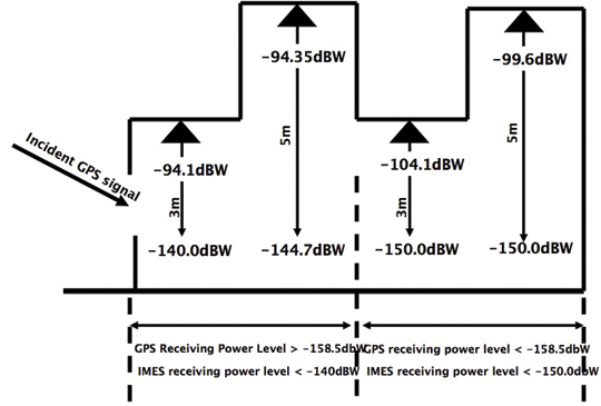
Since IMES shares the same frequency as GPS L1 band (1575.42 MHz), there is an interference level that IMES may have on GPS signals. This interference has been studied in detail by conducting experiments and simulations. Based on these studies and analysis, various methods have been considered to avoid harmful interference to GPS signal. To avoid such interference, IMES center frequency is shifted by +/– 8.2 Khz from GPS L1 band. This will have the least impact on the GPS L1 band signal. For example, if the IMES signal is –110 dBm (very strong) and the GPS signal is –142 dBm (very weak), the loss of GPS signal (C/N0) due to IMES is less than 2 dB. If the IMES signal is –120 dBm and the GPS signal is –142 dBm, there is no loss of GPS signal (C/N0). Based on this analysis, the IMES transmitter power must be controlled such that the maximum power to the receiver does not exceed –110 dBm at a distance of 3 meters from the transmitter. Figure 5 shows the guideline specified in the QZSS IS document for setting the transmitter effective isotropic radiated power (EIRP)based on location.
Figure 5. IMES transmitter power setup guideline in QZSS IS document.
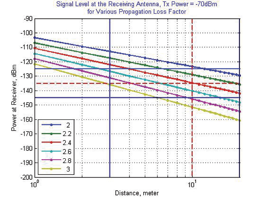
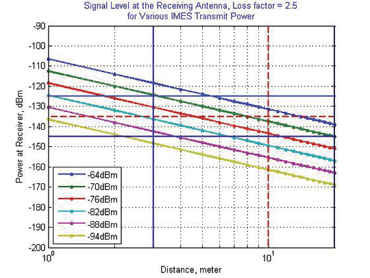
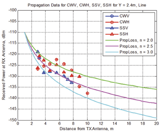
Figure 6 shows the signal propagation loss for transmitter power of –70 dBm for various propagation loss-factor values of n. Figure 7 shows path loss for various transmitter power for the same loss factor, n = 2.5. These graphs shows the maximum power that shall be used to cover an area without exceeding the maximum power level. If a single unit of IMES cannot cover the complete area, then multiple IMES units will be deployed to cover the entire area with suitable power level. These graphs serve as a guideline for setting transmitter power.
Figure 6. Signal path loss for –70 dBm signal for different path loss coefficient, n.Figure 7. Signal path loss for path loss coefficient, n = 2.5, for different transmitter power levels.
The signal propagation loss is calculated using the following equation; the gain of transmitter and receiver antennas is considered as unit gain (0 dB).
Hence, the equation depends on distance from the transmitter, d, and the propagation loss factor, n. The value of n is 2 for free space and increases for areas with objects that obstruct the signal. An office with soft partitions may use n = 2.5. The graphs can be used as a guideline to estimate the transmitter power to cover an area within the allowed power levels.
Application Areas
IMES can be used wherever indoor position data is required. It depends upon the application for that particular location as well. For example, an infrastructure-related safety application should have IMES installed at all elevators, escalators, staircases, emergency exits and routes, fire-fighting unit locations, and so on. Here are some of places where IMES might be used:
Every room of a building, to provide exact room location.
At entrances, exits, elevators, escalators, staircases, public facilities, and corridors for indoor navigation.
At every emergency exit for guidance.
Along hallways and lobbies at set intervals to guide the user.
In front of shops for advertising and information.
In sign posts to provide user’s location and guidance.
Complement other positioning systems like Wi-Fi, RF Tag, UWB, and so on.
As an indoor ground control point for surveying of large and multi-storey buildings.
With security cameras to provide accurate position data.
In factory production lines for automated control of moving objects.
Business Perspective
IMES technology was developed with the guiding concepts of low-cost global implementation and ease of installation and use. Low cost on the transmitter side is achieved by developing large-scale integratin (LSI) chips and IMES installation, setup, and database management tools. At the receiver side it is achieved by design of IMES signal so that existing GPS receivers in mobile phones, PDAs, or any other devices can use IMES by modifying only the firmware. The signal is designed so that it can adapt to other GNSS signals available in the future, for example, Galileo, QZSS, or Compass signals, requiring only firmware modification. Global implementation is made possible by signal design compatibility with existing GPS or GNSS signals. Ease of use is achieved again by signal design: one IMES transmitter can provide 3D position data, including floor information, with reliability and accuracy of a few meters even in deep indoor locations.
The development of IMES LSI chips (IMES transmitter) will also lead to development of value-added products for many consumer household appliances. For example, the green energy concept produced low-power LED lightbulbs. IMES chips can be installed in LED bulbs at very low additional cost. Similarly, it can be built in many other products like power socket devices, security devices, timing devices, and sensors where position data is also critical. This will provide an opportunity for the manufacturers to provide value-added products to users with indoor positioning devices. Not only electrical products but some construction materials or interior decoration materials like gypsum (dry
wall) boards can be made with built-in IMES chips. Installation of one piece of wallboard with an IMES built-in chip can provide position data in the room, reducing installation cost while not affecting the interior design of the room.
Implementation of IMES will also lead to new applications in the field of location-based services and applications where position data are necessary. It can also lead to new applications using IMES as an indoor electronic ground control point (GCP) in large buildings and indoor areas.
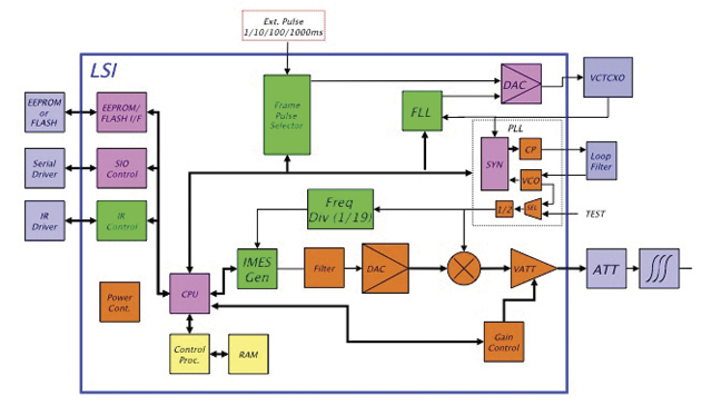
Chip Development. To reduce IMES transmitter cost, the IMES LSI chip has been developed and will be available by the end of the third quarter of 2011. This will reduce overall cost and size, and create platforms to develop value-added products integrating with other devices and systems. The chip is designed for global communications systems like personal handy-phone system (PHS, a mobile phone communication system developed in Japan), CDMA, and GSM. Figure 8 shows a block diagram of the chip transmitter.
The basic specifications of the LSI chip are: size, 12 x 12 millimeters; power, to be determined; maximum transmit power, –30 dBm or –60 dBm (user selectable); frequency, L1 band, 1575.4282 MHz or 1575.4118 MHz (user selectable); PRN codes, 173–182 (user selectable); signal type, GPS L1C/A, with upgrade capability to other GNSS signals.
Installation and Management
An IMES installation, setting, and management system has been developed to facilitate deployment. The main purpose of the system is to provide IMES transmitter position data (latitude, longitude, height) without conducting precision surveys, thus reducing installation, setting, and management costs. The system helps locate optimum locations for IMES transmitter siting, control transmitter EIRP power, set PRN IDs, and assign position data. The system can also use various types of map data sources to generate necessary floor data or indoor maps in 3D. The inputs can be either 3D vector data or 2D raster images, or even paper maps.
The overall system consists of four sub-systems:
IMES Setup Tool (ISET). This tool is used to set up the IMES transmitter. It provides two basic functions: to set up signal-related data (setting PRN code, transmitter power, navigation message rate, and so on) and to set up message-related data (position data, floor data, message types and their contents, message sequence, and so on). The R&D version of IMES also allows transmitting some special data for research and development purpose. It is possible to change the preamble value different from GPS, load a different PRN code table than IMES, change the navigation message data rate, generate a BOC(1,1) signal to test L1C-like signals, and change the RF frequency. The setup tool also has user-access management so that only authorized users can change certain sensitive data like PRN code, position data, and transmitter power.
IMES Database Management Tool (IDBM). This tool simplifies installation and management by providing a necessary database including a building-related database, a service-provider database, a device-related database, other integrated sensors database (if any), and a signal-related database. Since IMES is controlled and managed, guaranteed and authorized services can be provided for dedicated applications. This enhances the reliability of an IMES-based positioning system for infrastructure, security, and safety-related applications.
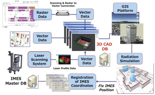
3D Mapping Tool (IMAP). This tool, shown in Figure 9, provides a 3D map database for IMES either for implementation or end-user applications. The mapping tool can use 3D vector data (for example, existing DXF files), raster image data, or direct user input. A laser scanning system with CCD camera is used to generate 3D data if existing data is not available. The tool creates walls, windows, doors, ceilings and other smaller objects from the laser data. If data are available in paper drawings, they are scanned to create raster images before digitizing them into vector format.
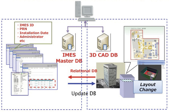
Figure 9. 3D Map Database Development System.Figure 10. Concept of IMES database for implementation, setting and management.
The system will ultimately create a 3D database of a building at floor level that can be linked with external databases. Figure 10 shows the overall concept of the IMES database system that includes both IMES database and 3D map database. The two database systems are linked by a relational database system. Any update in the map database can be reflected into the IMES database.
Signal Propagation Loss Tool (IPMODEL). This tool simulates the signal level where IMES will be set up. It is necessary to have optimum deployment of the transmitter to cover the area as large as possible within the allowed power level. Although the allowed maximum EIRP power level is –64 dBm for Japan, the approach is always to use the least power possible to cover the area, to avoid any possible harmful interference to other systems as well as to limit the availability of the signal to only the desired area.
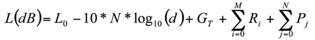
The following equation is used to calculate the signal path loss which is based on Frii’s free-space path-loss model.
GT is the transmitter antenna gain. The receiver antenna gain is assumed to have unit gain (0 dB) and hence not included in the model.
L0 is the power loss at 1 m distance and is given by 20 x log10(signal wavelength) — 20 x log10(4*pi).
N is the path-loss factor, which is 2 for free space, 2.5 for office room with soft partition, and 3.0 for rooms with hard partition.
Ri is loss due to i number of reflections by objects.
Pj is loss due to j number of penetrations through objects.
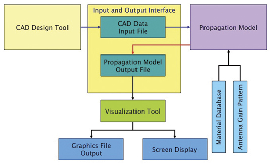
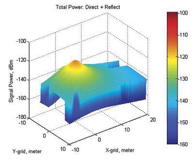
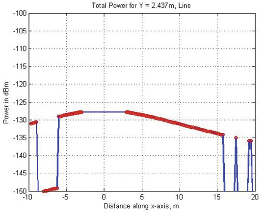
Figure 11 shows the propagation-loss tool flowchart. It uses 3D map database provided by the 3D mapping tool and database from the database management tool. It also uses antenna gain pattern and material electrical properties to compute the power loss due to reflection and penetration. Figure 12 shows the signal propagation output from the model for a building lobby. Figure 13 and Figure 14 show the output from the propagation loss results from the actual measurement and model output, respectively. The results match within a difference of few dBs.
Figure 11. Path Loss Tool flowchart.Figure 12. 3D view of signal power in a building lobby.Figure 13. Actual signal power measured at different locations in the lobby shown in Figure 12Figure 14. Signal power output from the propagation loss tool at the same location shown in Figure 13
Experiments and Demonstrations
Experiments and demonstrations have been conducted to validate the IMES concept, uses, and applications. Early experiments validated the
concept, message design, and interference analysis. Later experiments focused on actual implementation for infrastructure, and social-network and location-based applications. Pilot projects have been conducted in collaboration with the Japanese government to test IMES capabilities for seamless positioning and navigation and for social infrastructure platform.
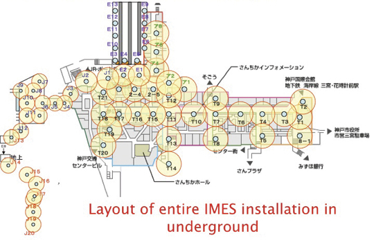
The Free Mobility Project in Kobe is the biggest social experiment using IMES for seamless navigation under the sponsorship by the Ministry of Land, Infrastructure, Transport, and Tourism. The project was conducted in an underground shopping mall of Kobe railway station. Shopping mall visitors were asked to participate in the navigation using IMES-capable mobile phones. Most visitors could follow the route they had chosen or find the destination point using the IMES set-up.
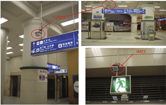
A total of 70 IMES transmitter units were installed at locations including ticket counters, elevator entrances, emergency exits, fire-extinguisher locations, staircases, station entrances, and alleys of the shopping mall. Figure 15 shows a part of the IMES transmitter location map. It covers one of the sections of the shopping mall. Figure 16 shows various locations where IMES transmitter devices were installed. As shown in Figure 17, intelligent 3D route guidance can be performed based on user preference. For example, a user in a wheelchair must be guided by a route that has no staircases, shown by green route in the figure, to reach the destination. A pedestrian can be guided by red route, which is the most direct route to the destination.
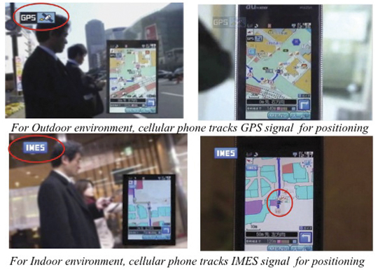
Figure 15. IMES transmitter location map to cover the underground shopping mall in Kobe Station.Figure 16. Installation of IMES near the station entrance and emergency exit.Figure 17. Intelligent 3D route guidance using IMES.Figure 18. Seamless navigation by mobile phone using GPS and IMES.
The distribution of each IMES transmitter is done in such a way that it covers a radial distance of 10 to 20 meters. The deployment density of IMES depends on the location environment. If an IMES device is located near the entrance, the coverage distance will be around 10 meters to minimize transmitted power. IMES devices in deep indoor locations can cover a radial distance of about 15 to 20 meters.
Commercially available mobile phones with a firmware update for IMES were used to receive the IMES position data. The phones also included the shopping mall and station map including related databases for various applications.
Conclusions
IMES can provide reliable and guaranteed 3D position accuracy, including floor information. IMES signal design is done in such a way that it can use existing as well future GPS/GNSS receivers without any hardware modifications. Necessary implementation, setup, and management tools are also developed to facilitate IMES installation and to minimize the cost so that large-scale global implementation is possible. IMES LSI chips are being developed for large-scale implementation. IMES will also help in developing many other location-based applications and services. IMES evaluation kits will soon be available for joint R&D projects.
IMES technology-related patents have been filed in Japan and many other countries. The basic patents have already been approved in Japan. GNSS Technologies invites academic institutions to participate in joint R&D projects.
Dinesh Manandhar is a visiting researcher at the University of Tokyo, where he received his Ph. D, and a senior researcher at GNSS Technologies Inc. He is one of the designers of IMES message structure and involved in developing indoor navigation system based on IMES for seamless navigation environment. He can be reached at [email protected].
Hideyuki Torimoto is the president of GNSS Technologies Inc. Japan. He established Trimble Navigation Japan and Weathernews Inc. in 1986. He also established the Research Forum on Social Infrastructure for Advanced Positioning (NPO) in 2003 and the Satellite Technology Laboratory in Tokyo University of Marine Science in 2004. He served as Satellite Division Member of ION for 2003-04. He can be reached at torimoto @ gnss.co.jp.
An Assisted-GNSS Solution Uses the EGNOS Data Access Service
By Kevin Sheridan, Tomas Dyjas, Cyril Botteron, Jérôme Leclère, Fabrizio Dominici, and Gianluca Marucco
For use in billing drivers in road-user charging schemes, onboard units employing GNSS must meet stringent reliability and availability requirements, and at the same time, be based on low-cost equipment systems. The SIGNATURE unit includes an assistance service which provides ephemeris data and corrections from EDAS, optimized for user location.
As roads become more congested, governments and regional authorities seek better ways to manage their existing networks. Road-user charging (RUC) is increasingly promoted to tackle the congestion challenge: charging drivers a fee, perhaps on a monthly billing basis, derived from the distance their vehicles have traveled, time of travel, and whether congested roads were used.
Recording trip information with a GNSS receiver in an onboard unit (OBU) provides a convenient and flexible means to support automated fee collection. For GNSS positioning to be used as the basis for billing drivers, however, it must meet stringent reliability and availability requirements, and at the same time be based on low-cost equipment.
We have developed a prototype to provide both the positioning availability and integrity required for this application. The Simple GNSS Assisted and Trusted Receiver (SIGNATURE) includes an assistance service that provides ephemeris data and corrections from the European Geostationary Navigation Overlay Service (EGNOS) Data Access Service (EDAS), optimized for the user location. Assistance messages are sent to OBUs that can either host an experimental receiver or a commercial-off-the-shelf (COTS) receiver. Data from the receiver is processed with application-specific navigation algorithms on the OBU that aim to improve the integrity of the position solution relative to standard solutions.
Field trials have assessed the contribution that assistance can make to positioning performance, and illustrate options for enhancing standard assistance solutions. Enhancements to assistance encompass modifications to the message content and alternative means of communications, showing the benefits and feasibility of a broadcast service. The impact of including EGNOS corrections through a broadcast assistance service in urban areas is also under investigation.
GNSS Road-User Charging
RUC has the potential to reduce congestion, lower vehicle emissions, and generate revenue streams for infrastructure improvement. It can ensure that revenues are based on actual road usage, creating a financial incentive for changing driving behavior. This might include lower overall use of private cars and, in particular, reducing peak-time travel levels in urban areas by effectively spreading out the morning and evening rush hour. RUC can also encourage commuters to use alternative forms of public transport.
To automate the process of collecting charges, electronic fee-collection (EFC) systems have been developed based largely on dedicated short-range communications (DSRC). In a DSRC solution, a simple tag on the vehicle receives a signal when it passes a roadside beacon and a charge is computed accordingly. Cameras with automatic number-plate recognition (ANPR) technology are also widely used, mainly as an enforcement tool.
Both technologies rely on fixed roadside infrastructure. As charging schemes to date have focused on specific areas (individual cities) or road infrastructure (major motorways, tunnels, and bridges) this type of technology provides an adequate solution.
To meet future policy goals, however, this is not feasible. More extensive charging schemes covering greater areas, more road types, more classes of vehicle, and which will vary charges depending on location and time of day require a far more flexible solution. Flexible schemes require the positioning element to be onboard the vehicle. GNSS-based devices, possibly augmented with other sensors, have been identified as the best option to achieve this.
Using GNSS, the OBU tracks the location of the vehicle, and this is matched against the road network to calculate a charge. A GNSS solution can support many different charging strategies including time distance and place (TDP) based charging for road sections, geographic areas, and cordon schemes. While GNSS offers great potential, several operational and performance limitations have prevented more widespread adoption. Operationally, OBUs are relatively expensive, fraud prevention is potentially complex, and charging schemes must also accommodate infrequent users. GNSS performance is limited in terms of the ability to provide sufficiently accurate positions with high availability and integrity in all operating conditions.
To be fully flexible and to target congested areas, OBUs must work in all environments including urban areas. Urban-canyon problems, with satellite signals blocked and reflected, are well documented. In some cases, not enough signals are available to determine a position, and when there are enough satellites, the ranges will be prone to errors and the geometry is likely to be poor. Signals are more likely to be available in the longitudinal direction of the street, but with few or no satellites on either side of the vehicle. Signal blockage is a particular problem when the GNSS receiver is started up, and it attempts to decode satellite ephemeris data. This requires around 30 seconds of uninterrupted tracking with a relatively strong signal for each satellite, and in an obstructed urban environment it may take many minutes to determine the first receiver position.
Charging schemes typically aim to charge for at least 99 percent of road usage. If a typical journey length is 30 minutes, this means that only 18 seconds with no usable position solution can be tolerated and hence time to first fix (TTFF) must be below 18 seconds, and ideally much lower.
When positions can be determined, they must be sufficiently accurate to identify the correct road segment that the vehicle was on, and they must be reliable. Reliability, or integrity, becomes critical if road users are to be charged on the basis of GNSS-derived positions. Users must have confidence that they are being charged correctly for schemes to be effective and to gain public acceptance.
Whilst GNSS-based solutions are entering the market, for example in Germany and Slovakia for heavy goods vehicles, barriers to wider adoption remain. Many countries are considering GNSS-based road pricing, and they all face similar challenges in ensuring the accuracy, integrity, and availability of a GNSS-based solution for nationwide deployment.
SIGNATURE Solution
The principal objective of the SIGNATURE project is to prototype a GNSS-based solution for flexible road-user charging that can provide the required high integrity and high availability in a cost-effective and scalable manner.
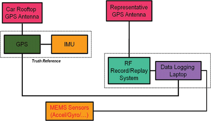
This robust, high-availability, high-integrity solution is delivered firstly through providing reliable assistance (A-GNSS) data from EDAS to optimize receiver acquisition and tracking capabilities and reduce TTFF, and secondly through implementation of embedded GNSS reliability algorithms into an OBU, providing assurance of positioning information (Figure 1, at top).
These features are intended to make a positive contribution in terms of the key RUC performance criteria, as defined by the GNSS Metering Association for Road User Charging:
Accuracy: right cost per trip
Integrity: probability and amount of overcharging
Availability: amount of charged usage.
Assistance Server. An assistance service supplying suitably equipped OBUs is one means to maintain rapid TTFF and meet the requirement for high positioning availability. The most significant contribution assistance can make to TTFF is to provide the
ephemeris data, which takes around 30 seconds to download from a satellite signal. Assistance data can also reduce the frequency search space when a receiver is acquiring signals, as the expected Doppler frequency can be computed from the approximate receiver and satellite positions.
The assistance server in SIGNATURE is based on EDAS, currently available as a beta version. EDAS allows a user to plug into EGNOS to receive the data collected by all the current EGNOS Ranging and Integrity Monitoring Stations (RIMS). This makes it possible to access EGNOS data when there is no clear sight to the EGNOS geostationary satellites, which can often be the case in urban areas, particularly at higher latitudes. As well as supplying EGNOS messages, EDAS also provides GPS observation and navigation (broadcast ephemeris) data, the key component as far as an assistance service is concerned. By recording the ephemeris data received at the extremities of the monitoring network, it is possible to ensure that the current ephemeris for any GPS satellite in view to users over Europe is available and can be supplied in an assistance message. Other data streams provided by EDAS can also be used to enhance the assistance solution.
The main enhancement tested in SIGNATURE was the use of EGNOS corrections within the assistance message. EGNOS today consists of a space segment of three geostationary satellites broadcasting correction and integrity information in the L1 band. Three sets of corrections are broadcast to users:
Fast corrections: used to compensate short-term disturbances in GPS signals, generally attributable to satellite clocks;
Long-term corrections: used to compensate for the longer-term drift in satellite clocks and the errors in the broadcast satellite orbits
Ionospheric corrections: broadcast as a grid of vertical delays (GIVD) from which a user receiver can determine a slant correction to be applied on each range measurement to compensate for the delay experienced by the signal as it passes through the ionosphere.
Fast and long-term corrections are added to the ephemeris data in the assistance message. Rather than relaying the GIVD data to the OBU and letting the receiver reconstruct the ionospheric grid and calculate slant corrections, this is done within the assistance server. A slant correction is provided for each satellite that will be in view at the user location. This approach is valid provided the OBU updates the corrections regularly enough to take account of the changing satellite elevations and ionospheric conditions. It provides a significant saving in terms of processing and memory consumption at the OBU, while still delivering the accuracy benefit of the EGNOS ionospheric data. To correct for the tropospheric delay, a zenith value (ZTD) determined from the RTCA model is also included in the assistance message. Mapping this zenith value to a slant correction to be applied to satellite ranges is a straightforward process easily accommodated on the OBU.
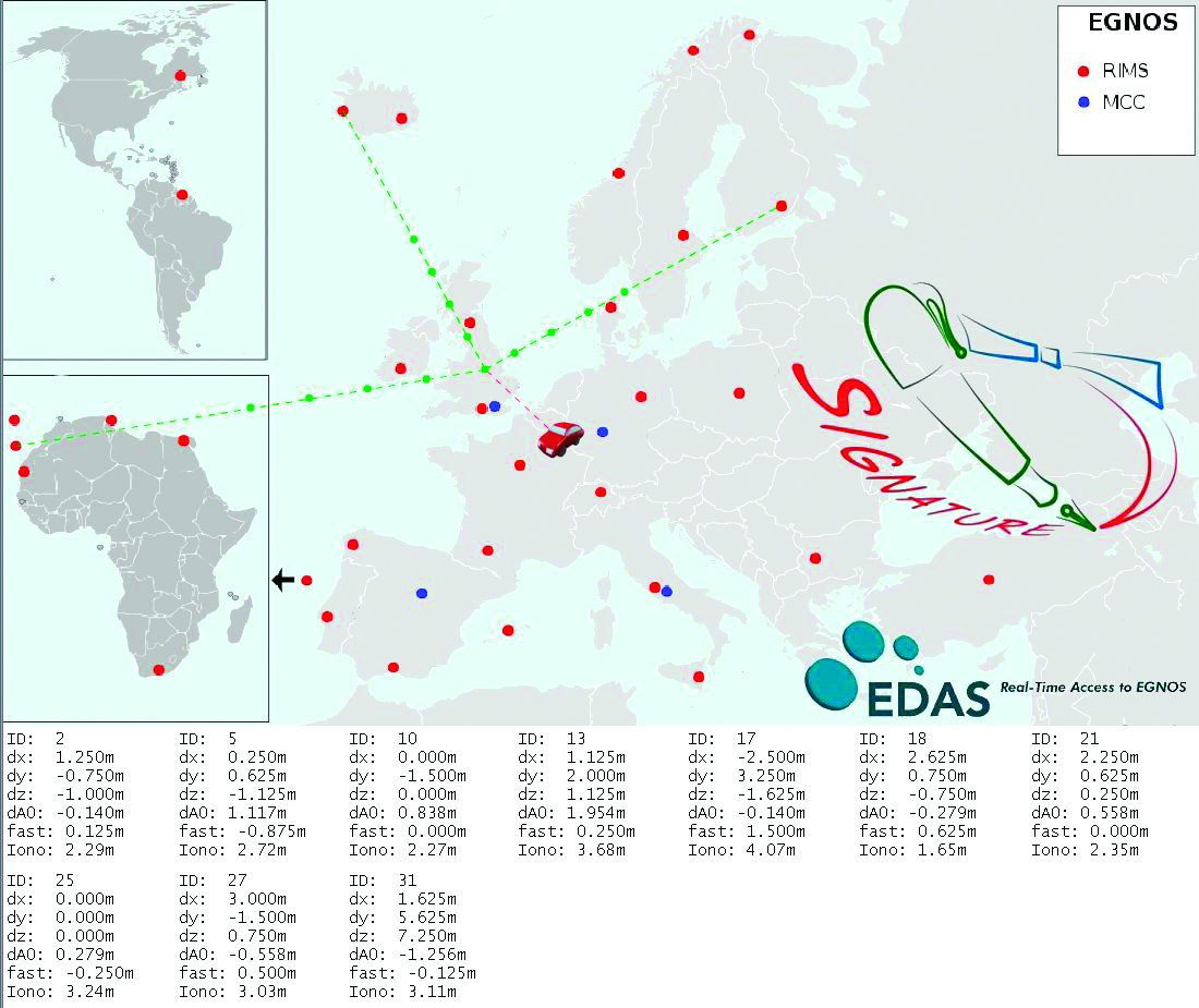
Figure 2 shows how data from EGNOS RIMS is collected at the assistance server at NSL in Nottingham, UK, and then used to generate messages. In this case, the assistance data was provided for trials conducted in Brussels. The figures at the bottom of the plot are the EGNOS correction values provided for all 10 GPS satellite in the positioning solution.
Figure 2. Schematic of assistance solution.
Further enhancements are also possible using the GPS observation data provided through EDAS. Firstly, for areas close to RIMS, a local differential solution can be applied using standard DGPS techniques to provide pseudorange corrections rather than wide-area EGNOS corrections. This has the potential to give greater accuracy for certain areas and is under investigation. By combining EDAS data sources, a GNSS performance monitoring and prediction service has also been created (Figure 3). This provides an assessment of GPS and GPS+EGNOS positioning performance (accuracy, availability of corrections, integrity) at known reference stations as well as monitoring the availability of EDAS data from its central server. Monitoring of this kind can be used as a further tool to identify system-level problems that might significantly degrade user positioning solution, perhaps to a level at which charges could not confidently be applied. It can also aid the enforcement process, as a diagnostic tool to identify if missing or misleading data from an OBU could be due to a system-wide fault or to a more localized source.
Figure 3. GNSS performance monitoring using EDAS.
This approach relies on the approximate user position being known at the assistance server. To maintain the validity of the corrections, it would also require a receiver to update its assistance data at a much high rate than would usually be the case. For a large-scale operation this would be unfeasibly expensive using cellular communications (GSM/GPRS), however it would be possible using a broadcast assistance approach. Using a radio data service (RDS) broadcast for example, ephemeris data and EGNOS corrections could be provided on a continuous basis. RDS is an auxiliary signal to the FM radio broadcast system and is used routinely for supplying travel information to in-car navigation systems. As data is broadcast from known locations and over a definable coverage area, messages can be generated that are applicable for all users receiving data from a given transmitter. A drawback of RDS is that it has a relatively low bandwidth, and it takes approximately 3.5 seconds to broadcast an ephemeris message for a single satellite. A further argument against RDS as a long-term solution is that analog radio signals are progressively being phased out in favour of digital alternatives. With the far greater bandwidth of digital audio bßroadcasting (DAB), ephemeris data for 12 satellites could be broadcast in less than 1 second.
We are evaluating alternative message content and transmission options to determine if real benefits can be gained by providing additional content, other than the ephemerides, in the assistance message.
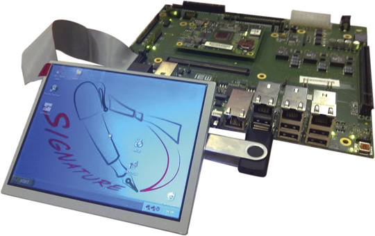
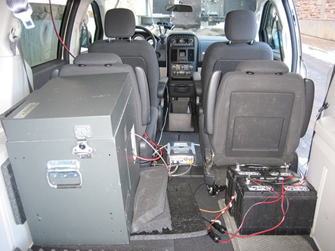
Onboard Unit. The SIGNATURE OBU (Figure 4) is based on a single-board computer (SBC) offering a high degree of flexibility. Developed by ISMB, it can host alternative receivers and positioning algorithms and manipulate different assistance data with a high degree of configurability. It is a powerful platform for developing and assessing OBU devices and their component parts, particularly as it allows lots of useful diagnostic data to be logged.
Figure 4. SIGNATURE Prototype Onboard Unit (OBU).
The OBU hosts a bespoke receiver which exploits the continuous availability of assistance data available through a high-speed data packet access connection and does not attempt to decode navigation data directly from satellite signals. This allows its design to focus on rapid signal acquisition with high sensitivity and to achieve a rapid TTFF even in areas where conventional receivers struggle. The SIGNATURE prototype has been designed using the well known SAT-SURF & SAT-SURFER platform.
The receiver, developed by the EPFL, implements massive parallelization by making use of the fast Fourier transform, leading to a processing power equivalent to approximately 650,000 equivalent correlators. The minimum sensitivity in acquisition is –145 dBm, obtained using coherent and non-coherent integrations. Thanks to the massive parallelization and the assistance, TTFF at –145 dBm is still below 3 seconds.
Positioning Algorithms. The OBU hosts positioning algorithms designed by NSL to provide high accuracy, availability, an
d integrity through exclusion of outlying measurements and provision of quality metrics (horizontal protection levels or HPLs). Numerous positioning algorithms and outlier detection strategies are being investigated. These include consistency checks applied to raw measurements and computed positions and receiver autonomous integrity monitoring (RAIM). EGNOS corrections are applied to improve accuracy and integrity indicators (user differential range error indices) are used as coarse fault-detection barrier. Consistency checks on measurements include differencing pseudoranges between epochs and checking that this rate is below a defined threshold. A RAIM algorithm is then applied to detect and exclude outliers before measurements enter the main navigation filter. Positions and velocities determined by the filter are then checked again as a further fault barrier. Checks at this stage identify if speeds are within expected ranges for the application and whether height changes are reasonable, for example.
The RAIM algorithm is based on the maximum normed residual method. For the detection procedure, the test statistic is calculated based on weighted sum of the squares of the residuals. This test statistic undergoes a globaltest (chi-square distribution), and is tested against thresholds that are computed based on the probability of false alarm (Pfa) and degrees of freedom (number of measurements minus number of unknowns). The exclusion procedure is based on an outlier detection technique also known as data-snooping, which is based on normed residuals and applied within the range domain. This technique uses measures of internal and external reliability, where the internal reliability gives estimates of how reliable the outlier detection procedure is, while the external reliability gives estimations of the influence of an outlier.
In the final step of the exclusion procedure, the maximum normed residual is tested against a critical value based on the normal inverse cumulative distribution, which in turn depends on the Pfa, and a decision is made on whether or not to exclude measurements. Having performed fault detection and fault exclusion until no further outliers are found, an HPL is calculated. This is the maximum horizontal position error that is guaranteed by the algorithm not to be exceeded, in accordance with the required probabilities of missed detection and false alarm. HPL is a function of visible satellites, expected error characteristics, and user geometry. Measurements which have been screened using the RAIM fault detection and exclusion are then processed in a Kalman filter.
Within the project, many alternative algorithms and configurations are being tested. As well as using RAIM in a snapshot mode to screen measurements entering the Kalman filter, fault detection can also take place within the innovation sequence of the filter itself. Weighting strategies that consider signal-to-noise ratios (SNR) as well as satellite elevations are also being used. This combined weighting is useful in reducing the impact of measurements affected by multipath in urban areas where simple elevation dependent models are often not applicable. The ultimate aim is to produce a robust GNSS positioning solution optimized for RUC in urban areas that balances the requirements of providing high availability with high integrity.
Test Methodology
The SIGNATURE end-to-end solution was tested in a series of field trials in the UK and Italy between April and July 2010. Trials took place in a range of operating conditions from rural areas with open skies to dense urban environments. In all trials, assistance data was provided from the service center in Nottingham, with messages tailored for the designated test area. The OBU recorded real-time position solutions as well as logging all raw measurements. Journey records can be sent back to the service center over a GPRS connection or can be downloaded back at the office. This allowed alternative solutions to be applied to the original datasets in post processing.
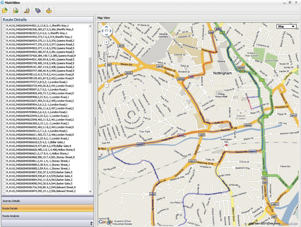
The position solutions were assessed through comparisons with high-accuracy GNSS reference solutions provided by additional onboard equipment and through processing with a map matcher (NSL’s Matchbox). Each journey record from a trial was compared against the known reference journey record to determine charging availability, accuracy, and integrity.
Using this approach, it is possible to assess whether improvements in the OBU position output are significant in terms of matching the vehicle location correctly to more road segments and with higher confidence. From direct comparisons between OBU positions and a high-accuracy reference solution alone, it is not possible to determine the significance of any changes in the OBU output in terms of final charging performance. Extensive trials of GNSS OBUs in London, for example, did not observe a relationship between location error (from OBUs) and performance at road segment level (map-matching) as map-matching can compensate for many errors. A strong relationship was observed between data availability and performance, though. Ultimately it is important to consider how successfully vehicle position can be related to charging objects, be they road segments, cordons or virtual toll-gates.
The objectives of the field tests were to:
Demonstrate that all elements of the end-to-end solution work as expected.
Assess the impact of assistance on TTFF.
Evaluate benefits of EGNOS data.
Investigate alternative positioning algorithms to optimize availability and integrity.
Demonstrate the feasibility of broadcast assistance using RDS.
Results
Field trials around Nottingham and Torino tested all elements of the solution. The tests confirmed the successful generation, transmission and use of assistance data, including EGNOS corrections. Position solutions determined onboard were transferred back to the service centre and processed with a map matcher. Figure 5 shows an example from a test in Nottingham city center, correctly identifying all the road segments travelled on.
Figure 5.Journey record view from Nottingham test. (Click to enlarge.)
Assess Impact of Assistance on TTFF. To examine the benefits of assistance, a series of trials were conducted to compare the TTFF of a consumer-grade receiver typically used in road applications against the performance of the SIGNATURE receiver that is assisted in all cases. They assessed TTFF for the COTS receiver in the following modes:
Hot Start: receiver has up-to-date almanac and ephemeris information so only needs to obtain timing/ranging information from each satellite to return its position fix;
Warm Start: receiver has the almanac information stored in its memory, but it does not have any ephemeris information. It also has approximate time and position knowledge. It can use this information to search for satellites but will then need to demodulate the ephemeris data from acquired signals;
Assisted: ephemeris provided over OMA-SUPL standard channel.
Table 1 shows the results from testing the receivers in open sky and urban conditions, specifically chosen to assess an extreme acquisition environment. In these tests when no valid ephemeris is available on a receiver at start-up, it takes an average of 28 seconds to determine a first position fix in open sky conditions. This increase to an average of more than 2 minutes in the worst-case urban environment as the receiver struggles to decode the navigation message on weak, noisy, and intermittent signals. With assistance, the SIGNATURE receiver maintains a rapid TTFF, outperforming the COTS receiver. The slower TTFF in the assisted COTS case may be partly due to the OMA-SUPL standard procedure
which is based on a more complex than the simple data transfer used in the SIGNATURE procedure. The COTS receiver is also decoding navigation subframes to determine signal transmission time. This can take up to 6 seconds depending on the point in the transmission cycle that acquisition begins.
Tests have also been carried out using a signal generator to control the strength of the received signal to assess acquisition and tracking sensitivity. At –145 dBm, the SIGNATURE receiver takes an average of 1.1 seconds to acquire 4 satellites and determine a first fix, and 5.1 seconds to acquire 12 satellites.
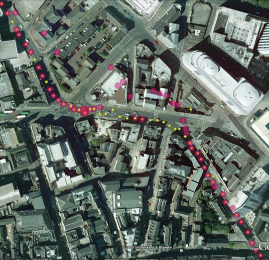
Positioning Algorithms. A variety of configurations have been investigated in the positioning algorithms, including applying outlier-detection routines at different stages of the solution and comparing snapshot and filtered approaches. Figure 6 shows a simple example of how the RAIM algorithm has been effective in detecting and excluding outlying measurements contaminated by multipath. By removing these meaurements and re-computing the OBU location, better position estimates are obtained.
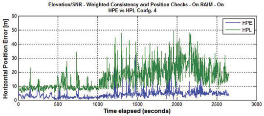
Figure 7 shows the accuracy and integrity of the SIGNATURE solution assessed using a high-grade GNSS/INS reference in Nottingham city center. In this case, the horizontal accuracy is 4.4 meters (95 percent), and the computed protection level is shown to bound the actual position error with the required confidence.
Figure 7. Position error and protection level, Nottingham city center.
In rural, semi-urban, and urban (Nottingham) conditions, a positioning solution has been demonstrated that supports all charging accuracy, integrity, and availability requirements.
Further tests were also conducted in the center of London, in a worst-case obstruction environment. In this area the current solution falls just short of the requirements defined for this project. In such cases, better performance could be obtained using a hybrid solution making use of additional sensor inputs, but this will increase equipment costs and potentially installation costs, too. A more practical approach may be to simplify charging schemes in the densest urban environments, using zones and cordons rather than using more detailed approaches that require a continuous high-performance positioning solution to be maintained in all conditions.
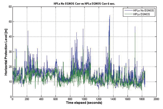
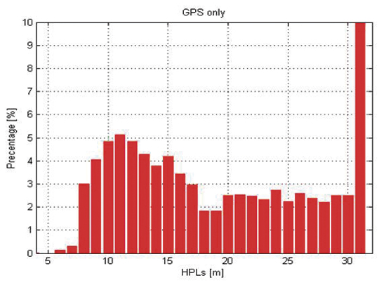
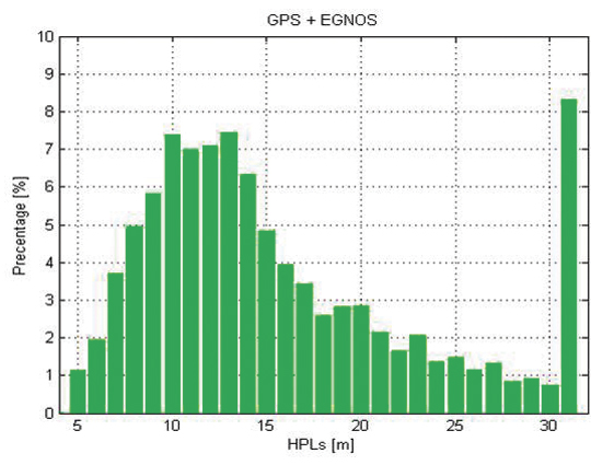
Benefits of EGNOS Data. The SIGNATURE solution has the ability to provide EGNOS data to positioning algorithms on the OBU and to vary the rate at which this information is updated and used. Field tests have assessed the potential benefits of this source of data in various environments, starting from the case in which EGNOS messages are continuously available for the positioning solution and then investigating how any beneficial effects lessen as the data is provided less frequently. The greatest benefit from EGNOS was derived by applying corrections prior to performing the RAIM FDE algorithm. This led to more consistent measurements and produced lower HPL values. Figure 8 shows a comparison for a Nottingham test in which a GPS-only solution is compared against an EGNOS solution in which a full set of corrections is provided.
Figure 8. HPL GPS vs GPS + EGNOS.
This reduction in HPL values through the application of EGNOS corrections is clearer when the distribution of HPL values falling into discrete bins is assessed (Figures 9 and 10). Similar levels of relative improvement have been found through using this approach in all test datasets. The significance of these improvements can only be judged against the detailed specifications of a particular charging scheme.
Figure 9. HPL distribution GPS.Figure 10. HPL distribution GPS + EGNOS.
Conclusions
Using an assistance service based on EDAS, it is possible to achieve a TTFF of a few seconds, which supports the high availability requirements of RUC. Field trials showed that providing EGNOS information over the assistance data link had an integrity benefit. Applying corrections prior to a RAIM algorithm leads to more consistent measurements and reduces HPLs. Robust positioning solutions have been developed and implemented on the OBU, and a test methodology has been put in place to assess the impact on charging availability, accuracy, and integrity. Results indicate that GNSS-based road charging offers the performance and flexibility to meet current and future requirements, provided availability and integrity issues are properly taken into account.
Acknowledgments
The SIGNATURE project has received funding from the European Community’s Framework Programme (FP7/2007-2013) under Grant Agreement No. 228237 and is supervised the European GNSS Supervisory Authority (GSA). Full details of the project can be found at www.gnsssignature.org. Any views expressed here are entirely those of the authors and do not necessarily represent the EC.
Manufacturers
The SIGNATURE receiver is based on the Terasic Altera DE3 System with a high-density Stratix III FPGA (EP3S260), and on the Rakon GRM8652 high-performance front end.
Kevin Sheridan is technical manager at Nottingham Scientific Limited (NSL),where he works on development of robust GNSS positioning solutions for urban applications. He has a Ph.D. from University College London.
Tomas Dyjas is a navigation engineer at NSL where he develops and tests positioning algorithms for an experimental OBU for road-user-charging (RUC) and evaluating novel integrity approaches for aviation.
Cyril Botteron manages research and project activities of the GNSS and UWB research subgroups at the Ecole Polytechnique Fédérale of Lausanne (EPFL) in Switzerland. He received a Ph.D. from the University of Calgary.
Jérôme Leclère is a Ph.D. student at EPFL. His research focus is on acquisition and high-sensitivity GNSS receivers.
Fabrizio Dominici is the head of technologies for Galileo/EGNOS applications and embedded systems at Istituto Superiore Mario Boella (ISMB). He received a master’s degree in communications engineering from Politecnico di Torino.
Gianluca Marucco received a master’s degree in electronics engineering from Politecnico di Torino. His research interests include multipath mitigation techniques for future Galileo receivers and real-time performance monitoring services for EGNOS.
A new method enables the mobile phone to compute its own position using acquisition assistance data with increased resolution in some of the fields. It benefits network operators as they can deliver the best performance with minimum bandwidth requirements, making this especially relevant in emergency-call situations.
By Javier de Salas and Frank van Diggelen
In assisted GPS (A-GPS) and A-GNSS, some information in the form of assistance data is sent to the mobile terminal equipped with a GNSS receiver. This data helps the receiver acquire satellite signals faster and at lower power levels as well as compute its own position. Assistance data is essential in many GNSS use cases but it is especially relevant in emergency calls from mobile terminals (e911, e112) where a fast response and the best sensitivity are required. Mobile subscribers are often in environments where direct satellite visibility is impaired because the user is inside a building or there are other obstructions. Emergency situations also require a very fast response (time-to -first-fix or TTFF), typically within 30 seconds, so the performance requirements imposed on the GNSS receiver are very stringent.
GNSS assistance data is standardized by 3GPP and 3GPP2 in two different types, broadly known as mobile-station (MS) based and MS-assisted. MS-assisted positions are computed by a server. MS-based methods enjoy certain performance benefits in position accuracy and response time when compared with MS-assisted methods. However, the amount of assistance data required for MS-based operation is substantially larger than the assistance data required by MS-assisted methods.
For this reason, some network operators choose the MS-assisted methods for their emergency-call services. Larger bandwidth requirements are of deep concern if many callers demand the services at the same time, because network capacity could be challenged when it is most needed.
This article describes a method that enables the mobile terminal to compute its own position, thus enjoying the benefits outlined above but with the same assistance data as in MS-assisted methods, only with increased resolution in some of the fields. We call this method single-shot MS-based. Network operators benefit because they can deliver the best performance with the minimum bandwidth requirements, especially relevant in emergency call situations.
Some 3GPP specifications will need to be modified slightly to increase the resolution of the relevant assistance data fields, namely, 3GPP TS 44.031, 3GPP TS 25.331, and 3GPP TS 36.355
Bandwidth versus Performance
Assisted GNSS information is exchanged between the location server and the mobile device using standardized protocols. Several bodies create different specifications: 3GPP, 3GPP2, and the Open Mobile Alliance (OMA). Broadly speaking, we can say that 3GPP and 3GPP2 work on protocols that are used over control plane and OMA works on protocols that are used over user plane.
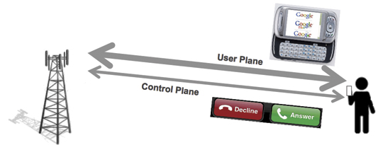
Control plane refers to the use of cellular signaling channels as the transport mechanism for the assistance data and position information. User plane refers to the use of traffic channels (see Figure 1). When you get a phone call, the control plane makes your phone ring. When you browse the web you are using the user plane.
Figure 1. Control plane is used for signaling purposes, user plane for transferring user data.
Signaling channels are not designed to transfer large amount of information, so it is important for 3GPP and 3GPP2 to make the protocols efficient and save bandwidth while maintaining the best performance. Cellular traffic channels are designed to transport much larger amounts of data and thus the bandwidth restrictions are less important than in the control plane case; OMA typically addresses richer GNSS features for Location Based Services (LBS). This is why network operators often support emergency call location using control plane, leaving the user plane for commercial applications. It is also a very good way to separate emergency traffic from LBS traffic so that the former is never compromised by lack of capacity coming from heavy use of commercial location applications.
Two different types of assisted GNSS have been standardized, known as MS-based and MS-assisted in Global System for Mobile Communicatios (GSM) and code-division multiple-access (CDMA) specifications, and as user-equipment (UE) based and UE-assisted in Wideband Code Division Multiple Access (WCDMA) specifications.
MS-assisted refers to the case where the mobile device equipped with a GNSS receiver does not compute its own position but it is instead computed in a location server in the operator’s network. Assistance data is sent to the mobile device to help acquire satellite signals faster. Remember that GNSS signal acquisition involves a three dimensional search (satellite, frequency and delay) that requires intensive signal processing. So assistance data is sent in the form of visible satellites including expected delays and expected Doppler shifts. These values are provided at a reference time and relative to an approximate location for the subscriber. The approximate location typically comes from the location of the serving cell tower. The reference time, but not the approximate location, is normally included as part of the assistance data. After a certain number of satellites are acquired, measurements are sent back to the location server for it to compute the subscriber position. GNSS measurements for each satellite include the measured delay, measured Doppler frequency and an estimation of the signal power to noise ratio. Assistance data in MS-assisted is referred to as “acquisition assistance”. It contains the minimum information so it is very efficient in bandwidth. See Table 1 for an exact bit count of the GNSS acquisition assistance. This table will be used as an example throughout this paper. In this particular example, it is assumed that assistance data is sent for 16 satellites.
MS-based refers to the case where the GNSS-enabled mobile device computes its own position locally. A different set of assistance data parameters are sent to the device to help it acquire the GNSS signals as well as calculate its own geographical location. Measurements are processed by the mobile device internal circuitry until the locally computed position is deemed accurate enough to meet the requirements received in the location request or a timeout is reached. Location information (latitude, longitude, altitude) is then sent back to the network in response to the location request. Assistance data in MS-based consists, at a minimum, of three elements: an approximate location (coming from the serving cell), an approximate time (accurate to a few seconds) and a description of the satellite orbits and clock errors referred to in the specifications as navigation model. See Table 2 for an exact bit count of the GPS assistance data in MS-based. The GNSS receiver uses the approximate location, the approximate time and the navigation model to estimate the expected delays and Doppler shifts of the visible satellite and thus proceed to the acquisition of satellite signals very much like in the MS-assisted case. Satellite measurements (code delays in the simplest implementation) and navigation model are used to calculate the receiver’s own position as explained below.
Advantages of MS-Based over MS-Assisted
We can see from Tables 1 and 2 that the amount of data used in MS-based i
s significantly larger than that of MS-assisted, in fact by a factor of seven! So why do some operators still decide to use MS-based over MS-assisted? The answer is there are noticeable performance advantages when using MS-based. An in-depth description of these advantages is out of the scope of this paper; but we will provide descriptions of what we see as the three more important ones.
Better Estimate of Position Accuracy. The first advantage lies with the fact that in MS-based mode the mobile device has a much better knowledge of the estimated accuracy of the position that it has computed internally. This was implicitly mentioned in the description of the MS-based and MS-assisted method above when we explained that in MS-assisted mode, the mobile terminal sends the measurements after a sufficient number of satellites (with certain range uncertainties) have been acquired. This is precisely the problem, what is a sufficient number of satellites? It is not easy to know for the mobile receiver because it does not know what positioning algorithm or what satellite subset the location server will use in its calculations. As such, it is more difficult to guarantee the quality of service of the position in the MS-assisted method. One could perhaps argue that the mobile receiver has an idea of the satellite geometry based on the Azimuth and Elevation fields (see Table 1) and therefore can perform a more educated estimation than just using the number of satellites and their associated uncertainties. This argument will only be valid if the mobile device knew exactly what the satellite subset is that the location server will employ in its position computation. Different satellite subsets yield different estimated accuracies. In addition to this, azimuth and elevation fields are optional in other positioning protocols such as Radio Resource Location Protocol (RRLP) and Radio Resource Control (RRC) and are also quantized with a value of 11.25 degrees, which deems them practically useless to quantify the satellite geometry in the critical cases where the dilution of precision (DOP) values are large.
Kalman Filter. The second advantage comes from the use of sophisticated navigation filters (for example, Kalman filters) by all GNSS manufacturers. In the MS-based method, the final position estimate that is sent to the network is computed using consecutive sets of measurements that help the position converge using the receiver dynamic model to smooth the resulting positions for greater accuracy. Conversely, in MS-assisted mode, the position computation engine only has access to a single set of measurements and therefore cannot employ sequential navigation filters.
Coarse-Time A-GNSS. The third advantage is perhaps the more difficult to grasp. It has to do with the fact that most (if not all) A-GNSS location servers only provide reference time information that is accurate to within a few seconds. On the other hand, for classical GNSS position computation, knowledge of absolute time accurate to a few milliseconds is required. Typically, it is the task of the GNSS receiver to decode the accurate satellite time information that comes modulated on the GNSS signals as part of the navigation message. However, in environments where satellite visibility is impaired, such as indoors, the satellite signals may be so low that the timing information cannot be decoded from the satellite due to excessive Bit Error Rate. In these situations, the absolute time can be set as an additional state that to be solved as part of the complete navigation solution therefore increasing the position yield in of the GNSS receiver in difficult environments. We refer to this technique as coarse time A-GNSS.
There is no technical reason why this technique could not be implemented in a location server in the operator’s network as opposed to the mobile device itself. However, for this technique to work properly, the mobile device should indicate to the location server whether or not it has successfully decoded the time from the satellites signals (or perhaps other sources). This is normally done by setting an associated time-uncertainty value with the time reported with the GPS measurements. There are some 3GPP specifications (for example RRC prior to R7) that do not support this parameter so they have hindered the adoption of the coarse time A-GNSS technique in MS-assisted mode.
Continuous Navigation. By delivering ephemeris data (good for several hours), MS-based techniques have an advantage over MS-assisted for continuous navigation. This advantage is not addressed further in this article, where we are focused only on first fixes.
Single-Shot MS-Based Method
We present a brief reminder of how GNSS positions are computed in order to determine what assistance data is strictly needed for a mobile terminal to compute its own location. We will use a simple least squares algorithm for simplicity but the conclusions are extensible to the cases of other positioning algorithms such as Kalman filters.
The observation equations are typically linearized around an approximate location. They can be easily presented in matrix form as:
Δ y = A Δ x
where Δ y is a column vector [m x 1] containing the difference between the predicted and measured pseudo-ranges for the m satellites measured by the GNSS receiver. The predicted pseudo-ranges can be obtained using the acquisition assistance data (codePhase and intCodePhase fields.)
Δ x is a column vector [4 x 1] containing the change in the “state” from the approximate position. The state has four unknowns x, y, z and b. x, y, and z are the change in the local East (longitude axis), North (latitude axis) and Up (altitude axis) coordinates from the reference position, b is the common mode error (mostly from the internal receiver clock error) in distance units.
A is an [m x 4] matrix, the first three elements in each row ux , uy , uz are the coordinates of the unit vectors from the receiver to the satellite, the last element is a 1 for the common mode error. A is sometimes referred as the geometry matrix.
Coordinates of unit vectors can be written as a function of the azimuth and elevation of each satellite. Simple trigonometry yields:
ux = cos (el) * sin (az)
uy = cos (el) * cos(az)
uz = sin(el)
In the coarse-time case there will be a fifth column of A containing the range rates, which are provided in the MS assistance data.
The goal is, of course, to determine the change in the state (our unknowns). Using simple least squares
Δ x = (ATA)–1AT Δ y
we can easily determine Δx. The coordinate changes in Δx (delta position) will be applied to the approximate location to obtain the new position.
Assistance Data Required
To re-cap from the previous section, we have seen that to compute Δx we need:
Expected pseudo-ranges for satellites in view (from acquisition assistance)
Measured pseudo-ranges (from the GNSS receiver)
Azimuths and Elevations for the geometry matrix (from acquisition assistance)
It would seem that if the mobile device receives acquisition assistance and measures the pseudo-ranges for a few satellites, it has everything that is required to compute a position (or at least a delta position) inside the GNSS mobile device. The delta position is relative to the position used to compu
te the acquisition assistance. Have we achieved our goal of computing position inside the mobile device with acquisition assistance? Not quite. Let’s now look at the acquisition assistance data in more detail.
We explained that we obtain the required expected pseudo-ranges from the acquisition assistance fields codePhase and intCodePhase. The codePhase field is defined with a resolution of one GPS chip, equivalent to 300 meters. Recall that we subtract the expected pseudo-range from the measured pseudo-range before we use the measurements in the position solution so this means if our expected pseudo-range was in error by, say, 150 meters because of the low resolution of this field, this is similar to making a measurement error of that amount, which of course will cause an unacceptable position error. This means the resolution of the codePhase field would need to be increased to be able to compute position. For a resolution of 2 meters, 8 more bits would need to be added.
The second topic of interest relates to the azimuth and elevation fields. These are needed to construct the geometry matrix A. As mentioned before, in 3GPP location protocols the azimuth and elevation of the acquisition assistance element are defined with a resolution of 11.25 degrees. Sines and cosines (needed to calculate the coordinates of the unit vectors) with such large angle errors will also yield large position errors. In Long-term Evolution Positioning Protocol (LPP), the situation has improved with the resolution being 0.7 degrees.
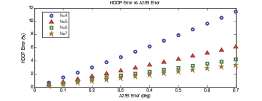
In an effort to quantify how the angle quantization affects the position error, we have run simulations that plot the 95 percentile of the HDOP error as a function of the angle error in azimuth and elevation (see Figure 2.) HDOP is proportional to the position error so this seems to be a reasonable choice. N is the number of satellites used in the simulations. As you might expect: the fewer the satellites the greater the effect.
Figure 2. HDOP error vs Az/El error. We use HDOP as a proxy for the expected position error: if the HDOP changes by 10 percent, we expect the position error to change by a similar amount.
We can see from the plot in Figure 2 that for an angle resolution of 0.7 degrees as currently defined in LPP, the 95 percent HDOP error is under 12 percent. If we wanted to make the worst error (N=4) under 2 percent, we can see that the resolution should be increased to 0.1 degrees. In order to meet this goal, 3 more bits would need to be added to both the azimuth and elevation fields in the acquisition assistance.
Another effect that must be noted is the possible change in the azimuth and elevation from the time the assistance data is received to the time the receiver computes its position (or delta position). In an emergency call scenario, typically we assume this time will not be greater than 24 seconds. Note the total allowed response time for an E-911 call is 30 seconds, including call establishment and network latencies. Simulations based on satellite geometry show that the worst-case effect is approximately of the same order of magnitude as the angle resolution discussed above, and therefore its impact in HDOP is just a few percentage points in the case of N=4.
At this point we seem to have everything we need to compute positions (or delta positions) inside the mobile terminal with the same acquisition assistance used in MS-assisted; albeit with slightly higher resolution in some of the fields.
To facilitate the comparison with MS-assisted and MS-based methods, Table 3 summarizes the exact bit count needed for Single Shot MS-based.
Optionally, if an absolute position is required in the mobile device instead of delta position, it would also require the approximate position (reference location) to be sent along with the rest of the assistance data (acquisition assistance, reference time). However, the MS-based performance advantages listed above can all be realized without the reference location, using only delta position. This is why we have not included Reference Location as an element that is needed for Single Shot MS-based.
Conclusions
We have seen that Single Shot MS-based can be used to enable all the MS-based performance advantages with, essentially, the same assistance data that is used in MS-assisted. Minimal additional bandwidth is required due to the increased resolution of some of the fields. Single Shot MS-based is therefore the best option for network operators that deploy A-GNSS based emergency location.
Not only does MS-based require significantly more bandwidth than MS-assisted (~ 7x) or Single Shot MS-based (~ 6x); but the absolute difference will increase with additional GNSS satellites such as GLONASS, SBAS, QZSS, Compass, and Galileo. Imagine all navigation models have to be sent for all satellites in view and for all GNSS constellations! Acquisition assistance can easily be made generic for every GNSS constellation since it is just “range and Doppler” and, in fact, this is the way it has been conceived in LPP where the dynamic ranges for all parameters are no longer restricted to GPS but allow other GNSS constellations.
Javier de Salas is director of GPS product marketing at Broadcom. Previously he worked at Ashtech, Magellan, and Global Locate. He has an MS in electrical engineering from Universidad Politecnica de Madrid.
Frank van Diggelen is chief navigation officer and senior technical director for GNSS at Broadcom. He is also a consulting assistant professor at Stanford University and is the author of A-GPS: Assisted GPS, GNSS and SBAS. He holds more than fifty issued U.S. patents on A-GPS and has a Ph.D. in electrical engineering from Cambridge University.
More Satellites, More Sensors Take Urban Navigation Downtown and Deep Indoors
By Frank van Diggelen
As we all know, GPS is practically perfect in every way — as long as it’s outside and unobstructed. Even cell phones can now produce meter-level accuracy under open sky. There are still many deficiencies in state-of-the-art location, particularly in deep urban canyons and inside large buildings. Which technologies will lead personal navigation into the future?
As we all know, GPS is practically perfect in every way . . . so long as it’s outside and unobstructed. Even cell phones can now produce meter-level accuracy under open sky. And, with Assisted GPS (A-GPS), those cell phones have mitigated the two great deficiencies of the original GPS: slow time to first fix (TTFF), and outdoor-only operation. A-GPS receivers can produce TTFF as fast as one second after a cold start, and (sometimes) work indoors.
However, there are still many deficiencies in the state of the art of location, particularly in deep urban can yons and inside large buildings. In the latter you will soon notice that even if your A-GPS operates in your house, it does not operate everywhere. The term “indoor GPS” is rather like “off-road vehicle”: your four-wheel drive may let you cruise down the beach, but you certainly cannot use it to climb every mountain nor ford every stream. Similarly “indoor GPS” denotes the presence of a capability — not the absence of all limitations.
And so what is the future of urban and indoor navigation, and which technologies will prevail? The short answer is: more satellites and more sensors. In this article we’ll look at the technologies that will move us from the era of GPS-only into the future of GPS-plus.
This is Manhattan.This is Manhattan on Wi-Fi.
Other GNSS
The most likely addition to GPS will be the other global navigation satellite systems, and all GPS receivers will be replaced by true, multi-system, GNSS over the next two to three years. Not because this will ever fully solve indoor location, but because of the outdoor problem in deep urban canyons.
When asked why he wanted to climb Everest, George Mallory famously said “because it is there.” Of the various GNSS systems, those with the most influence in the next few years will be GLONASS, because it is there, and QZSS because (as Mallory might have added) it is high. The first QZSS satellite recently began functional transmission. So let’s use QZSS as an example of why extra satellites are so important in the deep urban canyon.
Figure 1 shows Shinjuku, Japan, a typical deep urban canyon and a terrible place for GPS. The blue dots show the positions of a GPS receiver. The white and orange lines show the actual line-of-sight vectors to the GPS satellites. The white lines are to GPS satellites in direct view. The orange lines are to satellites behind buildings. However, the high-sensitivity A-GPS receiver tracks all these satellites, by acquiring and tracking reflected signals. Thus the whole concept of GPS — of measuring distance by time-of-flight — breaks down. The reflected measurements are inaccurate because of the extra path length. And even if the receiver could somehow tell orange lines from white, the horizontal dilution of precision (HDOP) of the white-only lines is 58 in this real-life example. Now add two high-elevation satellites, shown by green lines, and things are much better. The green lines show the location of two QZSS satellites, and the HDOP of the five green + white satellites is 3.
Figure 1 shows the problem of the deep urban canyon, and the value of extra satellites. The problem is that there are not enough satellites in direct view. This puts receiver designers in an insoluble dilemma: Track only strong satellites, and you will not have enough; or track weak satellites, and you will measure reflections with large measurement errors because of the extra path length of the reflection. Moreover, the reflected signals can be indistinguishable from direct signals in their characteristics, especially in mobile phones where the antennas are poor, and directional — so that signal strength is not a reliable indicator of whether a signal is direct or not.
This example should put to rest the false notion that extra high satellites will not improve HDOP. In this case the HDOP improves by about 20 times, from 58 to 3. It is easy to find many similar examples using GPS + GLONASS or any other GNSS combination. More often than not, extra satellites improve the situation significantly.
The QZSS system uses inclined geostationary orbits to provide high elevation coverage above Japan (and, as a by-product, neighboring regions.) In this respect it is unique amongst the major GNSS: it is exclusively designed to provide good urban coverage of its home region. Compass has a similar component, but ultimately it, like GPS, GLONASS, and Galileo, has global ambitions.
Some other satellite systems, such as satellite radio, use inclined geostationary orbits like QZSS. With QZSS providing an alternative example of a new GNSS, European taxpayers might well ask why Galileo should provide medium-Earth orbit satellites that spend more time over America and Asia than over Europe. As a U.S. taxpayer, I’m all in favor of the current Galileo plan — after all, the United States has been sending GPS satellites over Europe for the last 30 years, so a little reciprocation seems only fair.
Figures 2 and 3 show how the three satellites of QZSS provide better high-elevation coverage over Tokyo (and neighboring regions), than all of the 30 GPS satellites combined.
QZSS-capable chips are already found in mobile phones and tablets available in the Asian market. As this article was being written, a Broadcom BCM4751 chip in Tokyo was computing the first-ever GPS+QZSS position.
Figure 2. Elevation above horizon of the QZSS satellites, as seen from Tokyo. Note that the inclined-geostationary orbits of the QZSS system have been designed so that there is always one satellite above 70°.Figure 3. Elevation of GPS satellites as seen from Tokyo. About half the time none of the 30 GPS satellites is above 70° elevation, a quarter of the time one GPS satellite is above 70°, a quarter of the time two GPS satellites are, and for half an hour three GPS satellite are. The three satellites of the QZSS constellation provide better high-elevation coverage in Tokyo than the 30 GPS satellites.
Wi-Fi
After GNSS, the second-leading location technology is wireless local area networks, commonly known as Wi-Fi. Wi-Fi location works by using a database of media access control (MAC) addresses and locations. When a mobile device senses a Wi-Fi access point, the MAC address and database give the location of the access point (AP). A simple average of many APs gives position accurate to tens of meters.
Wi-Fi location is already tightly integrated with GPS in many smartphones. Wi-Fi location accuracy is good enough that it is often mistaken for GPS, especially in cities where the density of APs is large. In Manhattan, for example, there are more than 25,000 APs per square kilometer (see opening figure.)
Several major companies, including Apple, Broadcom, and Google, have worldwide databases of Wi-Fi AP
locations that are used in mobile devices, especially smartphones and tablets.
MEMS, Accelerometers, and Gyros
The micro-electromechanical systems (MEMS) technique etches the silicon on a chip to exploit its mechanical and electrical properties. A MEMS chip, such as a chip-level accelerometer or rate gyro, thus has tiny moving parts that can sense acceleration or rate of turn, respectively. Both sensors are already common in smartphones, where they are used to set the correct screen orientation (portrait or landscape), and for gaming. Because they are already there, they are a natural addition to location technologies, and many companies are moving rapidly to integrate motion sensors with GPS for improved accuracy indoors and in urban canyons.
As an example of the benefits of MEMS motion sensors, Figure 4 shows a test case where GPS was deliberately degraded by denying it the high direct-view satellites discussed earlier, and then adding nothing but low-cost MEMS sensors.
Figure 4. GPS-only positions and GPS + MEMS. The red circles show where poor GPS-only performance was dramatically improved by the addition of low-cost MEMS accelerometers and rate-gyros such as those already found in certain smartphones and PNDs.
Magnetic Compasses
Like accelerometers and gyros, magnetic compasses are already found in many smartphones. The technology is rapidly evolving, and different techniques are used by different suppliers to determine magnetic north, including Hall effect sensors, fluxgate compasses, and MEMS. Performance is dramatically affected by nearby metal and severely affected by magnets. You may not think that you are surrounded by magnets, but you are — especially in your car where every speaker of your sound system is a magnet — and the better the speaker, the larger the magnet. Thus magnetic sensors alone are not a reliable location technology, but integrated with other sensors, such gyros or accelerometers, they can be and are very useful, especially for pedestrian applications.
Altimeters
Altimeters are another MEMS technology. Typically a hermetically sealed cavity on the chip is used to measure change in atmospheric pressure — the surface of the cavity is deformed as the outside pressure changes, and the deformation can be measured using piezoelectric strain gauges. The integration of altimeters with GPS is already well established for such applications as hiking receivers. Similar integration is likely in other consumer devices, especially smartphones.
AFLT, MRL, and Cell-ID
The three cellular-wireless technologies of AFLT, MRL, and Cell-ID are all components of A-GPS.
AFLT (Advanced Forward Link Trilateration) is a technique used in CDMA phone systems, where the cell towers are precisely synced to GPS time. Because of this precise time synchronization, one can use the cellular signal to measure range from the cell tower, using time-delay just like GPS. CDMA phones with GPS are usually using AFLT when providing position indoors.
MRL (Measured Results List), is the UMTS analogy of AFLT for non-synchronized systems. The MRL provides a list of neighboring cell towers and received power. Received power is used to estimate range, and from this, position. Accuracy is not nearly as good as AFLT, but can be decent, especially in cities where accuracy may be better than 100 meters, good enough for emergency location applications such as E-911.
Cell-ID is simply the technique of looking up location in a cell ID database. This is analogous to Wi-Fi location, but not nearly as accurate since cell tower ranges are much greater than Wi-Fi. However, although perhaps the least exciting, this technique is the foundation of many important technologies. The AFLT and MRL techniques require Cell-ID as a necessary component. A-GPS usually uses Cell-ID for providing the assistance position, a necessary component of the high sensitivity that A-GPS provides. And Cell-ID alone is necessary for E-911 location, when A-GPS fails.
Digital TV and Radio
Location from digital TV works by measuring ranges from DTV towers, analogous to GPS and AFLT. However, DTV towers are not precisely synchronized to each other, and so DTV location requires the build out of fixed site infrastructure to deal with individual tower clock offsets.
DTV location is in a way the opposite of Cell-ID. While Cell-ID is intellectually boring, the technique is practically very important and widely used. DTV, by contrast, is an exciting idea, because it can be accurate like GPS but with much more powerful signals. However, it has been a commercial failure.
DTV location, or related technologies, may enjoy a resurgence in the future once mobile TV or digital radio (HD Radio and DAB — digital audio broadcasting) become more widely adopted.
Pseudolites
Well known to precison-location cognoscenti, pseudolites provide GPS-like signals from ground-based transmitters. They typically use a transmit frequency that is offset from GPS, but otherwise their signals are like GPS so that they can be used with a receiver with the same baseband as GPS.
Pseudolites can be very accurate, as good as five centimeters when using carrier-phase measurements. They require local, fixed transmitters which are fairly sophisticated (since they must maintain time and phase coherency to work properly.) This makes them prohibitively expensive for widespread applications. However, pseudolites are highly valued and widely used in niche markets, and will probably remain so.
IMES and Local Beacons
IMES stands for indoor measurement system, and it, or something like it, could be the most interesting new location technology of all. IMES is a local-beacon system — it works by providing a very weak signal that is exactly like GPS, but is meant for data-transmission only, not ranging. Thus it is fundamentally different from pseudolites, which are designed for ranging. The power of each IMES transmitter is so low (0.1 to 0.4 nanowatts) that it can only be acquired within about 10 meters of the transmitter. The signal is modulated with a PRN code (PRN numbers 173 to 182) and data: the data contains the location of the transmitter. The system technology may be summarized as “if you can hear me, here you are.” And the accuracy is inherently about 10 meters.
A fascinating detail of the IMES data message is that it contains (in message type 000): latitude, longitude and floor number.
IMES is designed to work with any GPS receiver that can decode PRNs 173 through 182. And, because they are not intended for ranging, the transmitters do not have to be precisely synchronized with GPS or with each other. This makes them cheap to build and install. However, they do still need to be deployed in large numbers (at least one every 10 meters), and will require a government-sized effort to become reality. Interestingly, they might just get it: The IMES system is defined in an annex to the QZSS interface specification from JAXA, the Japan Aerospace Exploration Agency. But it is not clear how much funding is available for IMES, or if there is any mass deployment schedule.
Even if IMES is never deployed, other, similar local-beacon systems may emerge. They will require a government-level (or similar) effort for the mass deployment required to make a system a reality for consumers.
Thus IMES or similar local-beacon technology may amount to nothing, or it may be a complete game-changer, depending on how the game is played and how the cards fall.
Summary
We have seen that GPS is practically perfect, when outdoors. And because A-GPS has worked so well over the last decade, it has become the predominant location technology in consumer platforms such as smartphones and tablets. But, precisely because of this success, GPS is more challenged than ever as consumers expect it to work where it was never meant to: indoors, in deep urban canyons, and with very small, cheap, antennas.
These challenges have led us to other technologies, in particular more satellites, sensors, and other wireless location techniques. The most prevalent and valuable additions to GPS in the next few years will be GLONASS and QZSS, as well as MEMS technologies, magnetic sensors, Wi-Fi, and cellular wireless technologies.
Roughly speaking, the 1960s and ’70s were the decades of GPS conception, the 1980s the decade of development and delivery, and the 1990s the introduction to the world. Since 2000 we have had the decade of mass-market adoption, and the 2010s will be the decade of GPS-plus: other GNSS and other sensors.
FRANK VAN DIGGELEN is senior technical director for GNSS, and chief navigation officer of Broadcom Corporation. He is the author of the bestselling textbook A-GPS: Assisted GPS, GNSS and SBAS, and holds more than 50 U.S. patents on A-GPS. He received his Ph.D. in electrical engineering from Cambridge University and is a consulting assistant professor at Stanford University.
This article addresses how best to quantify “which navigation system performs best” in a realistic testing scenario. The methodology focuses on land vehicles navigating in urban environments, but applies equally well to pedestrian navigation and can be adapted for testing assisted-GNSS implementations. During a drive test, the truth-reference system and RF recording system log samples to disk, with no need for the receivers under test to be included during the actual drive.
By Eric Vinande, Brian Weinstein, Tianxing Chu, and Dennis Akos, University of Colorado, Boulder
FIGURE 1. Traditional in-vehicle receiver testing.
Radio frequency record-and-playback systems (RPS) have recently become commercially available. These systems sample the RF environment and store it to disk during a drive test and can replay it through receivers back in the lab environment. Here we explore the improvements in dynamic testing methodology created by these units.
RPS test system installation.
RPS constitute a stark contrast to more traditional signal simulators that use pre-defined trajectories and mathematical models to determine appropriate RF output. Signal simulators attempt to reproduce environmental error factors such as multipath, inertial aiding system errors, and building and vehicle obstructions. They rely on mathematical models to simulate these various error sources. In some cases they do a reasonable job of reproducing these errors, but the dynamic urban environment is so complex (for example, rapidly varying/fading signal strength(s), multiple multipath signals, short/long duration obstructions of multiple layers) that even a sophisticated mathematical model can not replicate all effects completely. Some simulators include software that enables the user to define a trajectory and a limited amount of urban scenario details. Again, only so much realism can be created in a simulation environment. Existing testing standards are simulator-based, and as such, are circumscribed by the signal simulator limitations in representing a dynamic environment.
Positioning performance of a satellite navigation receiver under test (RUT) is coupled with its RF front-end system and local oscillator quality. Because of the variation in RF components between RUTs, some likely have superior RF interference (RFI) immunity. RFI can be a serious issue in certain land vehicles due to on-board electrical systems or because of external interference sources.
This article describes a testing method applicable to all receiver types, and complementary to that described in the December 2009 GPS World article by Mitelman and colleagues, “Testing Software Receivers,” regarding validation testing within a production environment. Added elements include taking into account truth-system uncertainty and a repeatability verification of the RF playback process through non-deterministic hardware receivers.
We present here the dynamic testing approach currently used at the University of Colorado in Boulder for receiver evaluation and comparison in the urban environment. The approach also includes the ability to assess the effect of sensor augmentations (for example, inertial, environmental) on positioning performance.
Truth Reference. Comparison with a truth reference system is essential for evaluation of satellite navigation receivers. For dynamic testing, this typically includes a survey-grade receiver coupled with a tactical-grade (or better) inertial measurement unit (IMU) and associated carrier-phase differential post-processing software. This software is filter-based and provides a positioning-error estimate in various components. Truth reference systems provide a continuous position estimate whose quality can vary depending on factors experienced in the urban environment, including length of full/partial satellite signal outage. In this study, we subtracted the 99th-percentile horizontal positioning error estimate of the truth system from the nominal RUT positioning error at each reporting epoch, as shown in Figure 2.
If the RUT position happens to lie within the truth-system position uncertainty, it is not considered to have any position error.
We focus here on a method to evaluate and compare mass-market, consumer-grade receivers to survey-grade receivers. One difference between these two receiver types is the way they handle the trade-off between accuracy and availability. Consumer receivers strive to provide the user with the highest availability, whereas survey receivers’ goal is to maximize accuracy. As a result, consumer-grade receivers will produce more regular position updates in harsh signal-tracking conditions, but must sacrifice accuracy to do so.
FIGURE 2. RUT position error calculation
Current Testing Standards
Currently accepted A-GPS standards such as those used by the 3rd Generation Partnership Project (3GPP) provide very limited dynamic testing in simulated urban conditions, being mainly designed to evaluate the first position calculation achieved in a particular simulated scenario. High-sensitivity receivers that pass or greatly exceed the 3GPP tests, in our opinion, are not guaranteed to have superior navigation performance in urban areas. Also, local oscillator performance is not specified. The trajectory dynamics imposed can actually be much smaller than the clock dynamics of a very low-cost local oscillator. A GPS receiver cannot tell the difference between the two and must track the effective Doppler variation.
The 3GPP defines five independent tests for A-GPS receiver certification. They include tests in the areas of: sensitivity with coarse/fine time assistance, nominal accuracy, dynamic range, multipath performance, and moving scenario/periodic update performance. The last three tests include elements that ostensibly pertain to the urban environment. These tests specify discrete, constant signal power levels for implementation in a hardware signal simulator. The discrepancy between the 3GPP-prescribed signal levels and those observed during actual drive testing is detailed as follows.
The 3GPP moving scenario/periodic update performance test trajectory is shown in Figure 3.
This test profile calls for the simulation of five satellites with a constant signal strength of 2130 dBm while the vehicle travels around the racetrack trajectory. In contrast, during an actual drive test in an urban area, a receiver reported the distribution of carrier-to-noise-density values for all tracked satellites as shown in Figure 4. This more accurately shows the range of signal strengths that should be expected in urban conditions.
FIGURE 4. Drive-test C/N0 distribution
The 3GPP moving test is considered passed if positions are reported regularly, and 95 percent of them are within 100 meters of the true position. This is not a particularly difficult test for a RUT to retain signal lock through, as the linear acceleration is about 0.15 g and the centripetal acceleration is about 0.25 g.
It is difficult for independent third parties to carry out a receiver evaluation following 3GPP guidelines as several of the tests require receiver restarts, which in turn requires testing automation. Depending on the receiver-evaluation hardware availability, restart commands may not be available to to an independent evaluator.
3GPP receiver testing results are quoted as pass or fail over a large number of short evaluations. For the dynamic environment, the system performance over continuous time is required to make a proper comparison between evaluated receivers.
In general, evaluating the GPS engines embedded within cell phones or other devices is difficult. Most are not made to interface with an external antenna, and the mere act of adding an antenna connection can significantly alter performance. The output format is not always documented, if it is even available to an end user. To allow fair across-the-board comparisons, GPS chipset manufacturers should make available development kits that have external antenna connections and well-documented message output formats.
Drive-Test Configuration
Current live dynamic testing requires multiple systems to be operating in a moving vehicle (see opening Figure 1). A truth-reference system, usually a high-grade GPS/INS device along with post-processing, provides the basis to which all other RUT are compared. This system requires a dedicated vehicle rooftop antenna with the best possible sky view, separate from a lower-grade test antenna located within the vehicle. Each RUT is connected to the representative consumer-grade antenna located in the vehicle through a high-isolation splitter that suppresses inter-receiver interference. It is important at this point that the gain be set appropriately for each RUT, depending on the front-end expectations while maintaining an equivalent noise figure across all receivers.
Visualization Methods
In addition to quantitative methods, we have created a qualitative visualization to assist with interpretation of the raw data. The same parsed data sets that provide the statistical script input are fed into a viewer script along with the post-processed truth reference data. With the truth-reference system data plotted in the center of the screen, each RUT is then plotted the correct distance and direction away, based on the distance and direction of error compared to truth. The receiver plots are overlaid onto Google Earth images centered on the truth-reference location. Plots of number of satellites utilized (top right of Figure 5) and elevation (middle right) as reported by each receiver and the sampled RF spectrum (lower right) are also included.
For each reporting epoch, based on the data frequency of the truth-reference system, a frame is generated with the aforementioned characteristics. These frames are gathered and encoded into a movie clip which can then be used as a quick and simple qualitative tool for receiver comparison. Figure 5 shows an individual movie frame. A forward-looking camera capability is also being added to this movie so the test environment can be documented from multiple angles.
FIGURE 5. Movie visualization screenshot
While observing this movie, variations in the sampled RF spectrum from interference or blockages can be associated with the current landscape. Locations of RFI sources can be identified and avoided (or included) in future testing. These RFI and significant blockage locations are of interest for receiver RF component and navigation filter development. The next three figures show spectrum snapshots during various parts of a drive test. In Figure 6, the cumulative GPS spectra rises above the noise floor and is visible during open sky conditions. While below ground level, Figure 7 shows only the front-end filter shape (and relatively minor RFI). Figure 8 shows an example of severe RFI when near a specific parking garage location.
FIGURE 6. Open-sky spectrum (centered on 1575.42 MHz)
FIGURE 7. Spectrum while below ground level (centered on 1575.42 MHz).
FIGURE 8. Spectrum near interference source (centered on 1575.42 MHz).
Record/Playback Concept
To overcome the limitations of hardware signal simulators and repeated vehicle drive testing, the RF record/playback testing method is utilized at the university. Commercially available equipment, capable of recording and playing back an RF signal, has recently become available. Equipment options exist for between $10,000–100,000, with 1–16 bit sampling and 4–25 MHz front-end bandwidth.
Figures 9 and 10 show the concept of “record once, playback many times.” During a drive test, the truth-reference system and RF recording system log samples to disk. There is no need for the RUT to be included during the actual drive test.
In the laboratory, the logged RF samples are replayed through a splitter to all RUT. The effect of receiver configuration changes can be evaluated without having to repeat the drive test. At a later time, additional receivers can also be tested using the same stored RF sample file.
During separate record and playback phases, testing considerations and methods discussed previously are implemented.
Since the recording process can only obviously capture current conditions, additional drive-test collections are required if different satellite geometry is desired, or if additional representative antennas need to be evaluated.
Repeatability of RPS Testing
To validate that the playback signal levels were not significantly different from live signals, we conducted an urban, dynamic evaluation. Figure 11 shows that there is typically not more than a 1 dB difference in reported C/N0 between live and playback modes when testing a receiver that only reported integer values. The two dropout instances were excursions into parking garages.
FIGURE 11. Live and playback C/N0 values
Figure 12 compares the navigation statistics between replays, using the same five playbacks as in Figure 11. The playbacks show a 1-sigma horizontal position solution spread under 1 meter for approximately 83 percent of the test.
FIGURE 12. Playback Horizontal Position Error Spread.
These two figures verify the repeatability of the RPS testing method and solidify it as an alternative to both signal-simulator testing and live testing of satellite navigation receivers.
Denver Testing Method
To evaluate the RPS concept, we conducted tests in three locations: Boulder, Denver, and Interstate Highway 70, all in Colorado. The Boulder and Denver locations were urban collections, while the Interstate 70 location was a natural canyon with significant elevation change. The collection at each location was repeated with two different representative antennas (patch and cell phone) at nearly the same sidereal time in order to keep the overhead satellite constellation similar.
We examine here the November 11 and 16 Denver tests. The November 11 test used a patch antenna that places nearly all its gain in the upward direction, making it more immune to interfering sources below and to its sides. Figure 13 shows the patch antenn
a location on the van, as well as the truth-system antenna location utilized for testing on both days.
FIGURE 13. Patch antenna (dashboard) and truth-system antenna (rooftop) locations.
The November 16 test used a cell-phone GPS antenna that does not have a preferential gain direction, making it more susceptible to interfering sources below and to its sides. This antenna type is representative of the typical low-cost antenna (in some cases as simple as a piece of wire) found in consumer cell phones. Figure 14 shows the cell-phone antenna suction-cup mounted to the front window of the testing van. The representative antenna mounting location was chosen to minimize locally-generated RFI effects while also being representative of a typical vehicle-use case.
FIGURE 14. Cell-phone antenna location.
The required equipment and connections are minimal when performing RPS drive testing, as no RUTs are included. The inset to Figure 1 at the beginning of this article shows the RPS unit in the rear of the van, mounted on layers of foam to reduce vibration, which, if not properly addressed, can cause errors in mechanical hard drives writing data at high rates. Also visible are the truth receiver on the center of the van floor, and the car batteries for powering it and the IMU. The IMU is mounted to the vehicle frame and is not shown.
The test drive trajectory through Denver on November 11 and 16 as reported by the truth system is shown in black in Figure 15 and is also repeated in Figures 16 and 17. The test lasted approximately 40 minutes on both days. It started in the upper left part of Figure 15 and continued zig-zagging through downtown to the lower right.
FIGURE 15. Truth trajectory for November 11 and 16 tests.
Figures 16 and 17 show particularly difficult blocks for the four receivers tested under the replay method. These receivers are denoted A (green), B (blue), C (red), and D (yellow).
FIGURE 16. Difficult block #1 during November 11 test and truth system antenna (rooftop) locations.
The horizontal positioning error statistics for two receivers on the November 11 test are shown in Figures 18 and 19. The left side shows horizontal error in two different zoom levels. The right side shows a histogram and cumulative distribution of errors, and several reporting metrics over the entire test. Even though receiver A in general outperformed receiver B, from the error time histories there are noticeable periods where both receivers simultaneously had positioning difficulties.
FIGURE 17. Difficult block #2 during November 11 test.
Table 1 summarizes the horizontal positioning statistics for all receivers during both tests. Positioning accuracy was severely degraded when replaying samples collected with the cell-phone antenna as compared to the patch antenna. Receiver A was the most accurate across both tests, while receiver B was the least accurate. The uncertainty of the truth system was subtracted out when producing the horizontal positioning results for all receivers.
Table 1
Conclusions
The record-and-playback system testing approach, in our opinion, represents the best way to test hardware receivers. It overcomes the fidelity limits of simulator-based testing, especially when considering the difficult-to-model urban environment. During receiver development, it requires only a single drive test for each location, as sampled RF data can be replayed from disk.
Having demonstrated that RPS testing is repeatable, we have produced a library of RF sample files representing real-world conditions for continued receiver development and testing purposes.
Eric Vinande is Ph.D. student at the University of Colorado studying GPS/MEMS inertial sensor integration and urban RFI aspects.
Brian Weinstein is a BSEE student participating in the Undergraduate Research Opportunity Program for GNSS receiver testing at the University of Colorado.
Tianxing Chu is a visiting researcher at the University of Colorado from Peking University where he is a Ph.D. student.
Dennis Akos is an associate professor within the Aerospace Engineering Sciences Department at the University of Colorado with concurrent appointments at Stanford University and Luleå University of Technology.
Manufacturers
Development of the methodology described here used two different RPS systems, one from LabSat (RaceLogic) and one from Averna. The test data come from the Averna system.