Point One Navigation is showcasing an ongoing collaboration with STMicroelectronics, a relationship that has made its real-time kinematic (RTK) and positioning engine solutions accessible to ST customers developing autonomous vehicles, robotics, and precision navigation applications.
AutoSens 2026, taking place in Detroit, Michigan, June 9-11, will bring together experts in the field of automotive sensing technology.
Point One Navigation’s software platform integrates seamlessly with ST’s new Teseo6 family of GNSS receiver chipset and module solutions to deliver a complete, off-the-shelf precise positioning system.
By combining ST’s GNSS receiver and measurement engine with Point One’s RTK correction service and advanced dead-reckoning algorithms, customers can achieve centimeter-level accuracy for their navigation solutions without the complexity of developing these capabilities in-house.
At AutoSens 2026, Point One and ST are collaborating to showcase an integrated solution that highlights the power of their joint technology. The demonstration features live precision location data and real-time performance analytics, illustrating the effectiveness of the Teseo6 automotive-grade solutions paired with Point One’s advanced dead-reckoning and corrections services in a variety of automotive and autonomous driving scenarios.
“Through our strong collaboration with STMicroelectronics, we are able to deliver proven precision positioning technology to ST’s global customer base,” said Aaron Nathan, CEO, Point One Navigation. “Our RTK and dead-reckoning software, combined with ST’s Teseo6 GNSS receiver, provides developers with a ready-to-integrate solution that matches or exceeds competing systems while accelerating time-to-market for robots, autonomous vehicles, and other applications requiring centimeter-accurate navigation.”
“The key to precise navigation is feeding the application a trusted position, that maximizes integrity and minimizes error,” said Mike Slade, GNSS product marketing manager, STMicroelectronics. “The collaboration between ST’s Teseo6 GNSS receiver and Point One’s complementary dead-reckoning and RTK correction services ensures high signal availability and the centimeter-accurate positioning needed for consistent and predictable operation.”
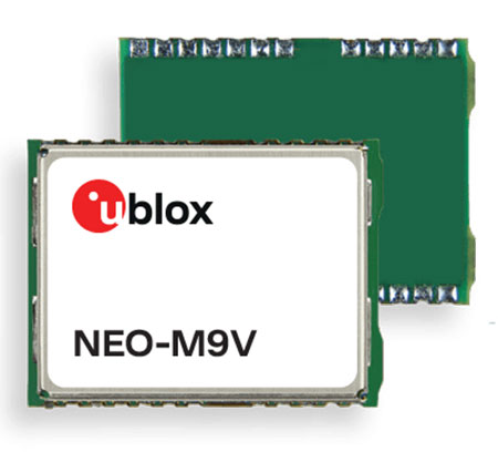
U‑blox has announced the NEO-M9V module, its first GNSS positioning receiver to offer both untethered dead reckoning (UDR) and automotive dead reckoning (ADR).
The NEO-M9V is suitable for fleet management and micro-mobility applications that require reliable meter-level positioning accuracy even in challenging GNSS signal environments such as urban canyons.
Using inertial sensor measurements, UDR offers a smooth navigation experience in dense urban environments by bridging gaps in GNSS signal coverage and mitigating the impact of multipath effects caused by GNSS signals that bounce off buildings. ADR further increases positioning accuracy in demanding environments by including the vehicle speed in the sensor-fusion algorithm.
Offering both UDR and ADR on the same module delivers maximum positioning performance and design flexibility, u-blox said. The NEO-M9V also features dynamic models optimized for both cars and e-scooters.
NEO-M9V is based on the u‑blox M9 GNSS technology platform. Its ability to track up to four GNSS constellations maximizes the number of GNSS satellites within its line of sight at any given moment. Integrated SAW and low-noise amplifier filters offer excellent interference mitigation for a robust solution. Compatibility with the NEO form factor reduces migration efforts for customers upgrading existing designs.
Continuous accurate navigation in all environments with sensor-based spoofing detection
Photo: U-blox
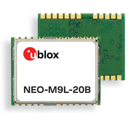
U-blox is introducing a series of automotive-grade positioning modules that are operational up to 105° C (221° F). The NEO-M9L modules and the M9140-KA-DR chip are built on the robust u-blox M9 GNSS platform and use dead-reckoning techniques to provide accurate position data when satellite signals are compromised or unavailable.
The u-blox NEO-M9L-20A and NEO-M9L-01A modules, as well as the M9140-KA-DR chip, are specially designed for first-mount automotive solutions. The modules and the chip are all automotive-grade, with the NEO-M9L-01A variant offering an extended operational temperature range up to 105 °C, making it suitable for integration on the roof, behind the windscreen, or inside hot electronics control units.
Applications include integrated navigation systems such as in-vehicle infotainment (IVI) and head units, integrated telematics control units and V2X.
The modules include new-generation 6-axis inertial measurement units (IMUs) that deliver low-latency 100-Hz RAW data output. The modules offer a low-latency 50-Hz position update rate, making it suitable for use in real-time applications. The automotive dead-reckoning (ADR) output combines the GNSS fix with IMU data to deliver accurate positioning output for various scenarios.
Additional GNSS-only output enables seamless integration into a variety of third-party applications. The receiver also supports wake-on-motion, which enables smart features such as theft protection and power-efficient designs.
The modules offer innovative sensor-based spoofing detection for advanced security and robustness. The chip offers protection against possible GNSS signal spoofing, which can cause navigation systems to report faulty position data or time.
“The u-blox M9 sensor-fusion products address the latest automotive market demands for quality, reliability and robustness. Availability and trustworthiness of position output are increased by using concurrent reception of four GNSS constellations,” said Aravinthan Athmanathan, product manager, Product Center Positioning at u-blox. “In addition, the spoofing-detection feature is brought to a new level compared to the predecessor. Paired with low-latency position output, attitude, and sensor data, the u-blox NEO-M9L is ready to meet current and future challenges facing the automotive market.”
All the module variants are compliant with AEC-Q104, the latest standard for ensuring the reliability of modules used in automotive applications. Engineering samples and evaluation kits will be available by the end of September.
Of the hundreds of papers researchers presented at the Institute of Navigation’s annual ION GNSS+ conference, which took place virtually Sept. 21–25, the following four focused on autonomous vehicle positioning for automobiles on city streets. The papers are available at www.ion.org/publications/browse.cfm.
Digital Maps with Tethered Positioning
The authors propose a new method for tight integration of digital map and dead-reckoning (DR) system (inertial measurement unit plus wheel odometer) to provide reliable navigation solutions in challenging GNSS environments for extended periods. Integrated DR and GNSS have been widely used as the backbone of any navigation system for the internet of things (IoT) and vehicle navigation applications. Dollar-level micro-electro-mechanical system (MEMS) inertial measurement units (IMUs) aided by vehicle-wheel odometers have been recently used as low-cost DR systems to bridge GNSS gaps in harsh environments, such as urban canyons, tunnels and under bridges.
However, DR drift errors rapidly increase over time and cannot satisfy most IoT and land-vehicle navigation requirements. Plus, the GNSS receiver may fail to provide accurate position or even experience a complete outage for more than 15 minutes, causing the tethered positioning error to reach several hundred meters. Because land vehicles are supposed to travel on roads, feedback from a digital map can be used to constrain their position.
The authors used a fuzzy-logic map-matching algorithm to identify the correct road segment on which the vehicle moves. A feedback filter senses a correct map-matched position as well as the road segment as measurement updates to the Kalman filter (KF) of the tethered positioning system. The proposed tight integration of digital maps and a DR system is evaluated using datasets collected by Profound Positioning Inc. in Calgary, Alberta, Canada. Results show the proposed method has an average of 0.15% of relative horizontal position error for Calgary datasets — a considerable improvement over the tethered-solution-only with 3.3% of relative horizontal position error. The average azimuth error of the proposed system is 1.3 degrees, while the tethered positioning system shows an average azimuth error of 9.7 degrees.
Citation. Yashar Balazadegan Sarvrood, Haiyu Lan, Aboelmagd Noureldin, Naser El-Sheimy and Profound Positioning Inc., Calgary, Alberta, Canada. “Tight Integration of Digital Map and Tethered Positioning and Navigation Solution for IoT applications and Land Vehicles.”
5G Signals for Opportunistic Navigation
This paper presents a navigation framework in which 5G signals are used for navigation purposes in an opportunistic fashion. A carrier-aided code-based software-defined receiver (SDR) produces navigation observables from received downlink 5G signals. The SDR produces navigation observables from 5G signals and a navigation filter in which the observables are processed to estimate the user equipment’s position and velocity.
An experiment was conducted on a ground vehicle to assess the navigation performance of 5G signals. In the experiment, the vehicle-mounted receiver navigated using 5G signals from two 5G base stations (also known as gNodeBs, or gNBs) for 1.02 km in 100 seconds. The proposed 5G navigation framework demonstrated a position root-mean-squared error of 14.93 m, while listening to signals from only two gNBs.
Citation. Ali A. Abdallah, Kimia Shamaei and Zaher M. Kassas, “Assessing Real 5G Signals for Opportunistic Navigation.”
Using Low-Cost Onboard Sensors
For autonomous vehicles, accurate positioning must be ubiquitous — reliably available at all times and in all places in which the vehicle is expected to operate. While GNSS commonly provides the basis for absolute positioning, it suffers from the problem of availability whenever a direct view of enough satellites is not possible. To address this failure mode, additional complementary sensors can be added to the overall navigation solution through a technique known as sensor fusion. Sensors such as inertial measurement units (IMUs), cameras, lidars, radar and more can be selected in such a way that the individual shortcomings of each sensor are mitigated, and the overall robustness and reliability are improved.
Although current autonomous-vehicle applications employ sensor-fusion techniques, they tend to rely on high-performance sensors to meet the accuracy requirements. These high-performance sensors tend to induce a much higher cost burden than would be acceptable for commercial production, and therefore make mass autonomy too expensive.
This paper focuses on using the lower cost sensors already available on most modern vehicles. These include low-resolution odometry and consumer-grade IMUs currently used for dynamic stability control and wheel-slip detection. A novel approach for combining vehicle speed, steering angles, transmission settings and multiple odometry inputs is presented along with achievable results while operating under a GNSS-denied environment. The test trajectory mimics a typical parking structure with many corners and short, straight segments. The only a priori information required for the filter is the wheel track and wheelbase (separation distance of the wheels).
A 90% performance improvement compared to the stand-alone GNSS/INS solution was observed during GNSS outages of up to 30 minutes. Furthermore, up to a 50% improvement was observed when comparing the multi-odometry to the single-odometry outages during the same 30-minute outage condition. Beyond GNSS outage performance, this paper shows how the use of the extra input to the filter can improve the positioning system’s protection levels to allow for more frequent engagement of the autonomous navigation system.
Citation. Ryan Dixon, Michael Bobye, Brett Kruger and Jonathan Jacox, “GNSS/INS Sensor Fusion with On-Board Vehicle Sensors.”
Radar and INS/GNSS
An autonomous vehicle requires a ubiquitous, accurate, precise and reliable localization system. Many sensors can be used for positioning and navigation, each with its strengths and weaknesses. Inertial measurement units (IMU) are usually used to build inertial navigation systems (INS). INS can be accurate for short durations; however, an INS accumulates errors and loses its accuracy quickly, especially when using low-cost MEMS-based sensors. GNSS can provide an absolute position and velocity to update the INS over time. A barometer provides absolute elevation information, and an odometer provides a speed update.
An integrated navigation solution consisting of an IMU, a GNSS-RTK receiver and odometer can perform well in open-sky areas and on highways. This system can achieve lane-level accuracy most of the time based on the condition of the sensors and the quality of the measurements. However, in downtown and urban environments, the degradation, multipath and blockage of the GNSS signal leads to poor performance for such an integrated navigation system, which is challenged to maintain lane-level positioning.
This paper presents a version of AUTO (formerly known as Coursa Drive), a real-time integrated navigation system that provides an accurate, reliable, high-rate and continuous navigation solution for autonomous vehicles by integrating INS, RTK GNSS, odometer and radar sensors with TomTom’s HD Maps. AUTO performs a tight nonlinear integration of the radar data and maps with the INS/GNSS/odometer system.
Results demonstrate that radar measurements and HD Maps can be tightly integrated with INS/GNSS in an effective manner, such that the integrated system can provide a high-rate, accurate, reliable and robust navigation solution. This is a crucial requirement for realizing a fully autonomous vehicle that can operate in urban environments under a wide range of conditions, including adverse weather and lighting conditions, even in downtown areas with degraded or denied GNSS signals.
Citation. Abdelrahman Ali, Billy Chan, Amr Shebl Ahmed, Medhat Omr, Dylan Krupity, Qingli Wang, Amr Al-Hamad, Jacques Georgy and Christopher Goodall, “Tight Coupling Between Radar and INS/GNSS with AUTO Software for Accurate and Reliable Positioning for Autonomous Vehicles.”
Road Navigation Using Multiple Dissimilar Environmental Features
New navigation paradigms combining GNSS and inertial with additional sensors can increase overall reliability and power robust road navigation. A feasibility study tests a barometer, a magnetometer and a camera looking at road signs, and concludes that such sensors examining environmental features can supply the necessary context for frequently traveled or shared routes.
By Debbie Walter, Paul D. Groves, Bob Mason, Joe Harrison, Joe Woodward and Paul Wright
Where a robust and reliable position solution is required, it is necessary to combine GNSS with other technologies. Dead-reckoning is only suitable for bridging short outages. For robustness against longer GNSS outages, alternative position fixing techniques are needed. Radio-based signals have been excluded from this study as they are either not yet mature or are, like GNSS, susceptible to jamming, though they may still play a part in the final navigation solution.
For land navigation in particular, a new approach is therefore needed. Environmental features provide a potential source of location information. These include buildings or parts thereof, signs, roads, rivers, terrain height, sounds, smells and even variations in the magnetic and gravitational fields. Visual navigation technologies are being developed and are likely to be complementary to the feature-matching discussed in this article; however, they will not be directly discussed. The environmental features will be integrated with dead reckoning to provide robust positioning.
The overall solution is to place hardware within a batch of vehicles, comprising multiple sensors, including a GNSS receiver and sensors for dead reckoning. Road map matching could also be included. During normal usage, the GNSS receiver is used for positioning and a database is updated with the feature information from all the sensors accompanied by location stamps from the GNSS-based position solution.
As the multiple vehicles travel around an area, the database is built up for these routes. In the event that the GNSS receiver does not receive sufficient signals to maintain an accurate position, the database is called upon for navigation by environmental feature matching. In this scenario, the sensors continue to take measurements and, by combining the knowledge of the last known location, dead reckoning and the sensor’s outputs, the positioning algorithm draws upon the database to estimate a positioning solution. This method is shown in Figure 1 and Figure 2.
Figure 1. Basic workflow mode for collecting data. Source: GPS World
Figure 2. Basic workflow mode for navigation using collected data.
This navigation system relies upon the roads being travelled on a regular basis so that the “maps” created from the sensor’s outputs are kept up to date and therefore valid. The most likely users of this technology would be fleets of vehicles that can share the mapping information. To focus on a typical system, use in emergency vehicles was considered. Knowing your position is vital in an emergency vehicle, and a system that incorporates a back-up to GNSS would be advantageous. The motivation for maintaining a continuous positioning solution is that, when moving within a complex environment, it is necessary to maintain the integrity of the current position. In emergency situations, delays are not acceptable and integrity is vital. There will be no point in time when the vehicle can be delayed to obtain a position fix.
Although this system will be designed with emergency service vehicles such as ambulances and police cars in mind, it could also be used in wider applications such as fleet management and tracking devices. Ultimately, crowd sourcing or cooperative techniques could be used to pool information from different vehicles equipped with the system. With a very large number of vehicles maintaining the feature database, the system could adapt to changes in the environment very quickly.
To reliably achieve meters-level positioning across a range of different challenging environments, a paradigm shift is needed. We need to use as much information as we can cost-effectively obtain from many different sources in order to determine the best possible navigation solution in terms of both accuracy and reliability.
This new approach to navigation and real-time positioning in challenging environments requires many new lines of research to be pursued.
ROAD EXPERIMENT
A set of sensors with a GNSS receiver were attached to a car and driven in closed loops around Stoke-on-Trent on multiple road types over multiple days. The loops were repeated three times on each day on four road types and then repeated over three consecutive days. The sensors used can be seen in Table 1.
Table 1. Sensors used in the road experiments.
The accelerometer, air quality sensor, barometer, dust sensor, light sensors and microphone interfaced with an Arduino microprocessor which outputted the signals from the sensors to a laptop. The Arduino sensors had a data rate of 20 measurements per second. There was an individual accelerometer (attached to the axel of the vehicle) for use in identifying road texture. There are also accelerometers that form part of the inertial measurement unit (IMU), and these were used for dead reckoning.
The onset of movement as recorded from the IMU was used to assist in identifying the beginning of each circuit. During the car journeys, there were two experimenters, one to drive the car and another to monitor the sensors. There were 5–10 minutes between each round; during this time, the sensors would be turned off and then restarted. The equipment was designed for the outputs of the sensors to be post-processed.
The four classes of road were suburban, urban, rural and high-speed road. The route taken and a view from Google Street View showing the general type of landscape traveled through is shown in Figure 3.
Figure 3. The urban road type used in the road experiment.
Figure 3. The suburban road type used in the road experiment.
Figure 3. The rural road type used in the road experiment.
Figure 3. The high-speed road type used in the road experiment.
A road experiment travelled the routes, using GPS receivers with the Arduino, video camera and the IMU so that GPS time could be used as a constant for the various sensors.
WHOLE ROUTE ANALYSIS
The outputs from the sensors were evaluated initially for their cross correlation over the whole route. This process assessed whether the data from different runs over the same terrain were similar and thus had a high cross correlation. This is vital for this map-building method of navigation. This section deals only with sensors that produce continuous output. The next section discusses discrete features.
Cross-Correlation Coefficients. The correlation coefficient (see online version of this article for derivation equations) is used to calculate the cross-correlation of two rounds of sensor data. The cross correalation coefficient is a normalized value. If a signal is correlated with itself, at zero offset (autocorrelation) this would give a value of 1; entirely uncorrelated data gives 0. Signals 180° out of phase would give a correlation value of –1.
The cross-correlation coefficients are shown in Table 2 for all of the sensors. It shows the coefficients for the four different road types using combinations of rounds (round 1 and 2, round 2 and 3 and round 1 and 3 for each three days) from the same days and the average of the coefficients for all the combinations. The sensors with higher coefficients are discussed in more detail in the following subsections. Road signs do not have cross-correlation coefficients; they are treated differently as this is a discrete measurement.
Accelerometer. The magnitude of the acceleration from a accelerometer triad was used in this experiment as a method of measuring road texture. A zoomed-in section of the acceleration as recorded from the accelerometer against the distance traveled can be seen in Figure 4.
Figure 4. Profile from accelerometer attached to axle.
It is difficult to see similarities in the output from the different rounds, although the accelerometer can show movement from stationary to driving and this was used to initialize the sensor outputs from the XSens IMU. This is shown in Figure 5 at 44s.
Figure 5. Accelerometer data showing vehicle setting off.
Barometer. The barometer measures height change of the vehicle. This sensor consistently produced the highest cross-correlation coefficient, shown in Figure 6.
Figure 6. Comparison of height profile over 3 days with minimums set to zero.
Magnetometer. The magnetometer produced data with distinct spikes caused by various magnetic anomalies in the environment being travelled through. This can be seen in Figure 7 for the high-speed road.
Figure 7. Vertical axis magnetic field profile for a high-speed road.
Figure 8 is a zoomed-in section of the magnetometer data from the high-speed road in Figure 7. It shows correlation with an offset of approximately 44m between round 1 and round 3. This is mostly due to synchronization errors between the magnetometer counter and the GNSS receiver clock. This is the reason a second run of the road experiment was completed.
Figure 8. Zoomed-in section of the vertical axis magnetic field experienced on a high-speed road.
Microphone. The microphone was able to pick up clear signals when the vehicle was stationary, and the signal seems to be dependent on the speed of the vehicle. Figure 9 shows the profile from the microphone.
Figure 9. Profile from microphone attached to axle.
It may be possible to combine this data with the accelerometer or odometer data to develop a clearer picture of what sound is resulting directly from the road surface and what is speed related, although this still may not result in a useful feature for this study.
Thermometer. Temperature can vary particularly in a rural environment, seen in Figure 10. Similarities are not consistent across environments as seen from cross-correlation values in Table 2 and are likely to change with the seasons and due to weather conditions.
Figure 10. Temperature profile for rural roads.
Light Sensor. Four light sensors were used in the experiment: upwards, forwards, left and right facing. Figure 11 shows the data from the upward-facing sensor on the high-speed road. There are distinct events where the light level drops. Many of these instances correspond to gantries (bridge -like structures spanning highways displaying speed limits and other information). These features could be treated as discrete, whereby the sharp dips in light level would be treated as momentary events. Some of the information would be lost in treating the ambient light as discrete, but it would make the feature more robust against changing light levels due to shadowing or cloud cover.
If light is treated as a continuous feature, it can be seen in Table 2 that the cross correlation was inconsistent. This is partly due to the effects of changing light conditions. On the days with direct sunlight, the light sensor would reach its maximum intensity and be saturated. This can be seen in Figure 11, and this affects the cross-correlation coefficient calculated.
Table 2. Cross-correlation coefficients for sensor outputs for the four road types.
Figure 11. The upward-facing light sensor profile for the high-speed road in second experiment day two.
Feature outcome. Thermometer data has been discounted as although it gave a cross-correlation coefficient of about 0.5 for the rural route, the other routes had lower cross-correlation values. Similarly, the microphone data had moderate success in high speed and rural environments but not in the other two routes. Therefore it will not be taken forward to the next phase although it could be used in the future if further processing was carried out on the data. As with the microphone, the light sensor had cross-correlation values greater than 0.5 in the rural and urban environments but had lower values in the other two. The success of this sensor is more reliant on the weather conditions than the environment type. At the current point this will not be brought forward to the next stage.
The accelerometer (used to measure road texture) showed no correlation with cross-correlation coefficients of approximately zero (between 0.0 and 0.3). It was useful for use in dead reckoning, but does not illustrate road texture.
The magnetometer and barometer showed the greatest potential for positioning with the highest cross-correlation values consistent over all the environments. These sensors are taken forward into phase 3.
DISCRETE FEATURES
A discrete feature is one where there are environmental events that occur at one position but can repeat multiple times along a route. The discrete feature can either be Boolean (an event occurs or does not) or it can be descriptive (different possible events or the strength of the event). Examples of discrete features include lamp posts, speed humps and shop signage.
In this paper, the discrete feature that will be discussed will be street signs, although the techniques used are applicable to many discrete features. How the signs are identified will also not be discussed in detail in this paper; instead, focus will be on how a sequence of discrete features is used show consistency across a route.
SCANNING METHOD
This section will look at scanning one round to find the region that best matches a region from a different round. Figure 12 illustrates this technique.
Figure 12. Diagram showing the principle used to scan for best match to a pre-set region.
The test data is scanned through the reference data. Cross-correlation coefficients are calculated as the test data is scanned through. The aim is to locate the position of the test data using the reference data for which the position is already known. The output of this exercise gives a cross-correlation profile (cross correlation as a function of position).
This profile can be treated similarly to a probability density distribution of position (although they are not the same) and so gives an idea of the probability of the position at each point in the test data.
Results. Two rounds from the suburban route are shown in this section as an example of the results achieved with the scanning method. Figure 13 and Figure 14 show the cross-correlation profiles for magnetic field and height for day 3 rounds 1 and 2 on the suburban route respectively. The test data region chosen is centered at 1.6 km into the route. The test data region size was 125 m for 4.5 km reference data.
It can be seen that the magnetic field has a number of peaks along the route. The peak with the highest cross-correlation coefficient is at the 1.6-km point (which is the correct position). For the height figure, there are many broad peaks at similar cross-correlation values approximately 700 m apart. The height peaks are broader than the magnetic peaks because the terrain height changes more slowly than the magnetic field.
Ambiguities, Dead Reckoning. The two graphs in Figure 13 and Figure 14 show that there are ambiguities present in both of the features. The majority of the features will have some ambiguities along a route, and so it is important to develop a technique that could mitigate them. One way ambiguities could be mitigated is by using the information available from dead reckoning. The dead-reckoning solution will have a specific position error (which grows with time), and the ambiguities from the features can be reduced by only considering the candidate position within the dead reckoning position uncertainty bounds.
Figure 13. Cross correlation scan for magnetic field on the suburban route with the center of the actual position of the test data shown as blue dotted line.
Figure 14. Cross correlation scan for the barometric height on the suburban route with the center of the actual position shown as blue dotted line.
COMBINING FEATURES
The quality of position information that can be extracted from a particular feature type varies with location. Thus, a better position solution can be obtained if higher weighting is attributed to higher quality features. Factors that will need to be considered include the precision of position that can be extracted from a feature, the level of ambiguity (Are there multiple candidate positions?) and the reliability (how much measurements vary unpredictably with time).
There are multiple ways to combine the scores from different features. Initially, there is the decision as to when in the position estimation process to combine the features. There are two ways to do this: Either combine the scores for each feature, or combine the position estimates for each sensor. The following subsections will describe a number of ways of combining the scores before estimating the position. It will be noted if these techniques could also be used to combine position estimates.
Equal Weighting. A simple combination technique is for each feature score to have equal weighting. The equal weighting used earlier took the two scores and found the average. This way, no single feature will dominate the navigation solution. As the feature scores are not probabilities, the values are not self-weighting, therefore it cannot be presumed that that equal weighting would always provide an optimal position estimation.
Test Data Weighting. This method takes a set of experimental data and empirically determines the weighting coefficients based on the best position solution in this test dataset. The test data would be used to maximize the score of the combined features using weighting at the correct position. This would have the benefit of using real data to determine the weighting, but its strength is based on how representative the test dataset is to the environments that the car will travel in.
Environment Weighting. This would detect the environmental context and use this to select an appropriate set of weights. For example, the presence of many Wi-Fi sources would suggest a suburban or urban environment, while a vehicle speed of 31m/s (70 mph/113 km/h) would suggest that the vehicle is likely to be on a highway. Based on this knowledge, it would possible to use a specific weighting coefficient set is developed for that environmental context.
Cross-Correlation Weighting. This weights each feature according to the characteristics of the cross-correlation coefficients profile obtained using the scanning method described earlier. This enables the weighing to adapt to the quality of the data. Figure 15 shows traits of a set of peaks that affect the confidence in the highest peak being the correct position.
Figure 15. Weighting nomenclature of actual position shown as blue dotted line.
Taking the uncertainty in the current position, only peaks that, for example, fall within 3 standard deviations would be evaluated. The characteristics of the tallest peaks compared with the others would be used to determine a measure of confidence for that feature.
There will be more confidence in the tallest peak (h0) if there is a greater difference between its height and that of the other peaks within the uncertainty range (h1, 2, 3). In Table 3 this is height.
Table 3. Cross-correlation profile weighting showing average distance from true position of the vehicle and the percentage of times the weighted scanning technique calculated the position within 100 m.
The next factor is the number of peaks within the uncertainty range (No. Peaks). The more peaks, the less confidence that the correct peak has been chosen as the position estimate.
The average cross-correlation coefficient within the uncertainty region (γ) would affect the confidence in the estimated position. If the average coefficient value (Av. CC) was similar to that of the highest peak, this suggests insufficient variation in the data being analyzed from that feature.
Finally, the standard deviation could be used. Calculating how many standard deviation (Std Dev) the highest peak was from the mean could provide a weighting value.
Each of these characteristics was looked at separately and compared against the benchmark of equal weighting using the scanning method comparing multiple pairs of rounds on different routes. It can be seen in Table 3 that the standard deviation from the mean provided the best weighting outcomes. To optimize the weighting algorithm, it may be that using a combination of these profile characteristics would provide the best position estimation.
Figure 16 and Figure 17 show examples of cross-correlation profiles; they show high and low confidence respectively. Figure 16 is the cross correlation of data from day three, rounds two and three, on suburban roads. It has a few spaced out peaks over the full profile, and one of the peaks is clearly higher than the others. Figure 17 is the cross correlation of data from day two, round three, and day three, round three, from the high-speed road. It has many similar height peaks all around the value of 0.5.
Figure 16. Good cross correlation profile; few spaced out peaks with one higher than all other peaks.
Figure 17. Poor cross correlation profile; many low similar height peaks.
CONCLUSION
Environmental features have sufficient variability spatially and stability temporally for a database of features to be developed to create a map of the environment. This supports the hypothesis that it is feasible to map a space and then create a feature-mapping and navigation algorithm using a combination of environmental feature sensors, a GNSS receiver and sensors for dead reckoning.
FUTURE WORK
The next step of the project is to develop a feature-matching, mapping and navigation algorithm that incorporates inputs from the multiple sensors, a GNSS receiver, map-matching and sensors for dead reckoning. The algorithm will run collecting sensor data while GNSS receiver data is available, and store this in a database along with location stamps until called upon in times of GNSS receiver signal disturbance. The data from the road experiments will be used for a test database in developing the navigation system.
ACKNOWLEDGMENTS
Debbie Walter is funded by Engin-eering and Physical Sciences Research Council (EPSRC) and Terrafix ltd.
The authors thank Paul Neesham for a method of manually recording street signs seen in video footage and Juliusz Romaniuk of Terrafix for advice and creating hardware that contained the sensors’ carrier frequencies.
DEBBIE WALTER is a Ph.D. student at University College London in the Engineering Faculty’s Space Geodesy and Navigation Laboratory, and a software engineer at u-blox.
PAUL GROVES is a lecturer at UCL, where he leads a program of research into robust positioning and navigation. He holds a Ph.D. in physics from the University of Oxford.
BOB MASON is chief scientific officer and director of Terrafix Limited, holding a Ph.D. in communications and neuroscience from Keele University.
JOE HARRISON is principal radio frequency design engineer at Terrafix Ltd.
JOE WOODWARD is a software design engineer at Terrafix Ltd.
PAUL WRIGHT is a development engineer with Terrafix Ltd., with doctoral degrees in physics and electronics.
Positioning chip company u-blox is making available its latest automotive dead reckoning (ADR) firmware for navigation, Telematics, eCall and V2X applications for both OEM and after-market applications.
Firmware ADR4.10 offers real-time, low latency positioning at up to 30 Hz using a combination of multi-GNSS, inertial sensor and vehicle speed data. The release also offers simplified installation, improved accuracy in dense urban environments and new messages for eCall.
ADR4.10 is available now to OEMs using u-blox M8030-Kx-DR professional and automotive-grade chips. By the end of May, it will also be available on NEO-M8L ADR modules, including the new automotive-grade NEO-M8L-02A.
u-blox ADR products are backed by specialist support at local and regional centers.
The untethered 3D dead-reckoning GNSS module NEO-M8U by u-blox is at the core of Navilock’s new GNSS receiver series for service vehicles. The new portfolio will enable retrofitting of dead-reckoning and untethered dead-reckoning (UDR) technology in any vehicle.
Photo: Navilock
Combining multi-GNSS (GPS, GLONASS, BeiDou, Galileo) with an onboard 3D gyro/accelerometer, the untethered dead-reckoning technology improves position accuracy even where GNSS signals are weak or unavailable, such as in urban canyons, tunnels or parking garages. Receivers with a serial MD6 interface can work in an extended voltage range from 5-48 Volt DC.
Applications for Navilock’s new GNSS receiver series include service vehicles from the police, fire departments, emergency physicians, disaster rescue teams and technical aid organizations that require accurate positioning at all times. Operational forces and their control centers must be constantly aware of their location to enable successful completion of any assignment. As a result, physical dangers and even life threats are clearly minimized.
“We have been collaborating for years with u-blox and highly respect the quality and reliability of its products,” says Karsten Reschke, Navilock product manager. “Particularly critical for our product range is the UDR technology that enables reliable and accurate location capability even without satellite navigation signals.”
“We are pleased to be associated with the Navilock brand and the quality and design reliability it represents,” says Andrew Miles, u-blox product manager. “The ease of use and robust packaging of these products perfectly enable the value of UDR in its target applications.”
Launched in 2016, the u-blox NEO-M8U enables reliable positioning even in case of GNSS signal interruptions, jamming, reflected or weak signals, and is independent of any connection to the car, other than power.
The eight new Navilock GNSS receivers will be available in Q1 2017.
Telit has announced the commercial availability of the SL869-3DR, a GNSS module for global use that leverages information from internal gyros, accelerometers and a barometric pressure sensor to perform dead-reckoning navigation for application areas such as track and trace and in-vehicle systems.
The module delivers accurate position data either directly from its multi-constellation receiver or from a fully autonomous dead-reckoning system, requiring no connections to external devices or components other than an antenna for satellite signal reception and power.
The module allows integrators to design zero-installation, in-vehicle navigation and tracking devices for fleets and other commercial or consumer applications that operate perched on the dashboard, connected only to vehicle power.
The SL869-3DR is a flash-memory based module capable of tracking three constellations simultaneously. The module integrates an array of micro electromechanical systems (MEMS) designed to provide it seven degrees of freedom. The innovative design of the internal sensor array in conjunction with the Telit MEMS-only Dead Reckoning (MoDR) software and intellectual property, deliver the host device unparalleled portable, turnkey dead-reckoning performance.
The Telit MoDR solution ensures that reliable position, velocity and time information is constantly available to the host application even when GNSS coverage is compromised, without the need for connection to the vehicle for wheel-ticks for speed or reverse-gear data. Its standard footprint lets navigation and tracking system integrators reuse existing device designs, eliminating complexity from external sensors and other apparatus, getting to market quickly with updated designs or product innovation.
“A significant number of the millions of commercial vehicles and fleets on the roads today are still operating with no or unreliable navigation systems because installation costs to connect the device to vehicle sensors are too high and require very specialized skills,” said Felix Marchal, executive vice president of GNSS and Short Range Wireless. “With the SL869-3DR we overcome that barrier because it enables devices that you simply connect to vehicle power and go. Up until now, ‘power-and-go’ navigation systems have largely relied on open-sky visibility, which is not typically where most commercial fleets operate. They are moving through tunnels, urban canyons and other environments where these systems cannot produce a position solution. Reliable MEMS-only dead reckoning, or MoDR as we call it, relies on very complex mathematical modeling and expert design of the sensor array. Developers must therefore, thoroughly scrutinize performance of the different products in the market. I am delighted that the SL869-3DR has outperformed competing products in its class across a wide range of test cases.”
The SL869-3DR is designed to support GPS, QZSS, GLONASS, Beidou and is Galileo ready. Telit MoDR technology boosts position accuracy in areas with adverse satellite reception conditions like urban canyons, overhead foliage, tunnels and parking garages. It integrates an embedded array of sensors including accelerometers, gyroscopes and a barometer (pressure sensor).
An antenna ON, antenna sense (open / short circuit) feature, allows the host application to inform the user of problems with the connection to the external antenna. An additional LNA delivers better sensitivity in harsh environments, better enabling devices with integrated antennas. The module also features fast calibration and is pin-to-pin compatible with the SL869, SL869-V3 and SL869-ADR.
Below is a video where performance the autonomous SL869-3DR MoDR is compared with the SL869-ADR automotive navigation module connected to vehicle sensors (wheel ticks and reverse signal).
u-blox has released its fourth generation firmware for 3D Automotive Dead Reckoning (ADR) GNSS modules and chip sets, the company announced during TU-Automotive 2016, which is being held June 8-9 in Novi, Michigan.
The Swiss-based company develops GPS technology, chip sets, miniaturized GPS modules, smart antennas and dead reckoning products. Designed for first mount or aftermarket road vehicle applications, such as in-car navigation, infotainment systems, telematics units and fleet management, the upgraded GNSS receiver now offers real-time continuous navigation output with an update rate of 20Hz, enabling low latency for applications such as interactive head-up displays.
The new firmware supports Galileo, GPS, GLONASS, Beidou, QZSS and SBAS. It also supports the Galileo-based eCall European emergency call system, which will be required in new vehicles starting in 2018.
The DR performance has been enhanced, the company says, which improves navigation performance, especially in highly urban environments where satellite signals are heavily blocked by and reflected from buildings. The high performance of the u-blox M8 concurrent positioning engine combined with the latest u-blox 3D ADR technology results in 100 percent coverage and continuous 3D positioning.
The new firmware will be delivered on u-blox NEO-M8L modules and is available for UBX-M8030-Kx-DR dead reckoning chips, including the new automotive grade variant supporting operation up to 105 degrees Celsius.
Qualcomm Technologies has introduced its latest Qualcomm Snapdragon automotive processors, the Snapdragon 820 Automotive family, offering a scalable next-generation infotainment, graphics and multimedia platform with machine intelligence and a version with integrated LTE (long-term evolution)-Advanced connectivity.
The Snapdragon 820A is Qualcomm Technologies’ newest automotive-grade system-on-chip (SoC). Qualcomm Technologies has taken a modular approach to designing the Snapdragon 820A, enabling a vehicle’s infotainment system to be upgradable through both hardware and software updates, thereby enabling vehicles to be easily upgraded with the latest technology.
The Snapdragon 820A’s sensor integration provides cognitive awareness and vehicle self-diagnostics, supports ADAS features for improved vehicle safety systems, and provides location and navigation through GNSS and dead-reckoning technologies.
Qualcomm Technologies is demonstrating the upgradeable module at the Qualcomm Automotive booth, North Hall #915, at CES 2016, being held in Las Vegas this week.
The Snapdragon 820A family is based on 14-nm FinFET advanced process node running Qualcomm Technologies’ custom 64-bit Qualcomm Kryo CPU, Qualcomm Adreno 530 GPU, Qualcomm Hexagon 680 DSP with Hexagon Vector eXtension (HVX), Qualcomm Zeroth machine intelligence platform, and the Snapdragon 820Am version with integrated X12 LTE modem capable of 600 Mbps downlink/150 Mbps uplink. The 820A is engineered with custom-built, highly optimized cores designed for heterogeneous computing — the ability to combine its diverse processing engines within the SoC, such as the CPU, GPU and DSP cores, to achieve previously unattainable performance and power savings.
The Zeroth initiative, a machine intelligence platform on Snapdragon 820A, is designed to enable automakers to develop state-of-the-art deep learning-based solutions using neural networks for advanced driver assistance systems (ADAS) and in-vehicle infotainment scenarios, and run them efficiently on embedded platforms in the vehicle. Zeroth accelerates execution of deep neural networks using the heterogeneous compute engines that are part of the Snapdragon 820A. A Zeroth-powered development kit for automotive solutions will be available for the Snapdragon 820A.
“With the Snapdragon 820 Automotive processing platform, we are delivering an unprecedented level of performance and technology integration designed to significantly enhance the consumer’s safety and in-vehicle experience. Never before has the unparalleled combination of integrated LTE cloud connectivity, powerful heterogeneous computing, leading-edge multimedia performance and breakthrough machine learning capabilities been delivered in a single chip, fully integrated, automotive grade solution,” said Patrick Little, senior vice president and general manager, automotive, Qualcomm Technologies.
“The automotive industry has long been asking for a single scalable solution capable of delivering the rich user experience and level of performance, connectivity and upgradability that consumers are accustomed to on their personal mobile devices,” Little said, “including real-time cloud connectivity and navigation, immersive 4K graphics and video displays, the flexibility of hardware and software upgradability, and the deep learning and remote diagnostic capabilities needed to deliver the next level of safety performance in the vehicle. The Snapdragon 820 Automotive platform has been designed to deliver all of these capabilities and much more.”
The version with integrated X12 LTE modem is designed to support continuous in-car and cellular connectivity, featuring the leading 4G LTE Advanced Pro that can support up to 600 Mbps download/150Mbps upload speeds, stream HD movies into the car, serve as a Wi-Fi hotspot supporting 802.11ac 2×2 MIMO, connect multiple mobile devices inside the car, and support 802.11p DSRC for V2X (vehicle to vehicle/infrastructure/pedestrian) communications. Local connectivity inside the car via Bluetooth supports content sharing between mobile devices brought into the car and the car’s infotainment system.
Qualcomm Technologies is also helping to lead the 3GPP in developing specifications for automotive V2X, for both LTE release 14 (LTE V2X) and 5G standards.
“Like Qualcomm Technologies, AT&T is committed to the connected car and takes a similar approach to technology development with the AT&T Drive platform, offering a global, modular solution to automakers to enable best-in-class user experiences for their drivers,” said Chris Penrose, senior vice president, Internet of Things, AT&T Mobility. “We design our solutions to provide better connectivity, flexibility and upgradability on our network, and Qualcomm Technologies’ development of the Snapdragon 820A Smart LTE Module is a prime example of this same approach to technology.”
By integrating advanced camera and sensor processing, the 820A supports critical always-on warnings and emergency services, extends standard cameras to Intelligent Cameras, and supports parking assist periphery vision features using surround view cameras. These features are supported by the on-chip Hexagon 680 DSP with HVX, which supports multiple automotive camera sensors connected simultaneously.
The Snapdragon 820A family of automotive-grade processors is designed for the automotive ecosystem and offers these features:
Scalable and modular platform offering pin, package and software-compatibility, with optional integrated LTE capability that is hardware and software upgradeable as wireless network technology evolves.
Supports vertical tiering options by offering the Snapdragon 820A family across premium to standard performance configurations.
Comprehensive software support for QNX, Linux and Android, as well as substantial platform-level integration of high value sub-systems to respond to the acceleration in refresh cycles while managing cost.
The connectivity, multimedia and graphics capabilities allow many real-time cloud based features, including streaming multimedia, enterprise collaboration, real-time maps and location services, remote diagnostics and one-touch telematics, with substantial potential for performance, connectivity and multimedia innovation for auto OEMs.
The upgradability option allows a wireless operator to offer an 820A Smart LTE Module concept for the version with an integrated modem that allows cellular connectivity to be updated through both hardware and software when new features become available on the cellular network.
Qualcomm Technologies is also collaborating with Aisin AW to develop the modular infotainment solution utilizing the Snapdragon 820A. “We expect the 820’s powerful features will deliver superior processing power, graphics performance and low power consumption demanded by next generation infotainment systems,” said Kyomi Morimoto, managing officer, Aisin AW.
Automotive samples of the 820A family are expected to be available in the first quarter of 2016. A number of concept vehicles and demonstrations based on the Snapdragon 820A, from Qualcomm Technologies and other automotive industry leaders, will be shown in the Qualcomm Automotive booth, North Hall #915 at CES 2016.
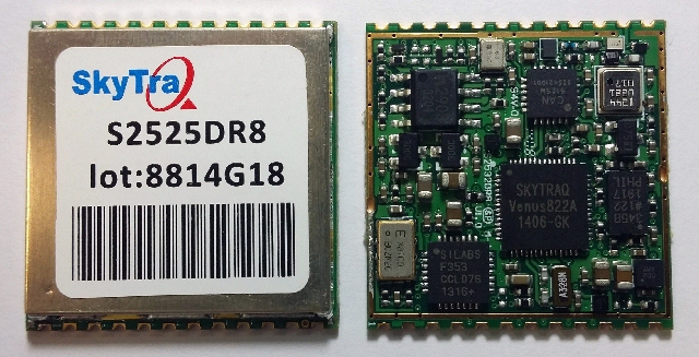
SkyTraq Technology, Inc., a fabless GNSS positioning technology company, has introduced an all-in-one S2525DR8 GNSS dead-reckoning module, with integrating MEMS sensor and interface logic on-board. The module is designed for road vehicles requiring high accuracy 100 percent positioning availability.
The S2525DR8 offers accuracy for both indoor and outdoor positioning. It is based on SkyTraq’s Venus 8 multi-GNSS platform and uses a high-performance automotive-grade XV-8100CB analog output gyroscope and 16-bit differential ADC. A 3D option adds a barometric pressure sensor on-board, offering improved accuracy for altitude reading and altitude change detection over an accelerometer-based scheme in 3D dead reckoning.
Another monitoring option adds an accelerometer on-board, offering high-accuracy vehicle acceleration monitoring for driver behavior characterization, accident reconstruction analysis, or trigger event recording. The S2525DR8 is compact at 25 x 25 millimeters. It contains a level shifter on board, capable of direct interface to a vehicle odometer and forward/reverse signals ranging from 3V to 30V.
The SPI interface pins on the module allow autonomous data logging to an external SPI Flash memory device. For high-performance vehicle navigation systems, S2525DR8 provides continuous navigation inside tunnels and underground parking lots without signals; highly accurate barometric altitude enables identification of which level the vehicle is on in a stacked multi-level high-way or a multi-story car park. For automatic vehicle locating or fleet management systems, location can be identified immediately after power on, whether the vehicle is outdoors or indoors under a signal-denied environment.
The S2525DR8 provides reliable, uninterrupted position, speed and heading information in challenging environments; it is suitable for demanding vehicle navigation and tracking applications requiring the highest accuracy and availability, SkyTraq said. The S2525DR8 is now being manufactured in ISO/TS 16949 automotive-certified factories; an evaluation kit, sample, datasheet, and reference design are available now. A 3D option with barometric sensor and a vehicle-dynamics monitoring option with accelerometer will be available in the first quarter of 2015.
Sensors in Motion (SIM) has introduced a MEMS (micro-electro-mechanical) navigation-grade inertial system (INS) that it says could transform the $8 billion/year inertial market with new products by offering price and performance specifications better than those currently available.
The first INS devices have been delivered to the Army CERDEC Night Vision Electronic Sensors Directorate (NVESD).
SIM, a spinout from NASA’s Jet Propulsion Laboratory and California Institute of Technology, is developing a family of high-accuracy MEMS gyroscopes, accelerometers and inertial measurement unit ( IMU) solutions. It says it has perfected unique MEMS structures using volume silicon wafer processing techniques to produce gyroscopes having ARW (angle random walk) less than 0.0035 degree/root-hour and bias instability less than 0.01 degree/hour with extraordinary vibration and temperature immunity, a performance comparable to ring laser (RLG) and fiber optic (FOG) gyros that are 20 times larger and 100 times more expensive.
These features are mandatory for numerous applications where location is not available from GPS or vehicle position accuracy is required including autonomous vehicles, drones, mining asset tracking, dead reckoning, agricultural seed placement, oil and gas directional drilling, self-driving autos, firefighter navigation, optical image stabilization, industrial equipment azimuth, aerospace and defense products and most GPS-denied environments, in addition to new applications.
Current devices would have a vehicle position off as much as 1 foot per second at 45 miles per hour.
“We see this technology opening an additional $2B sensor market needing size, weight, power, cost and performance that does not exist today. “ said David Smukowski, CEO of SIM.
With adequate resources the company says further performance gains are possible, even while shrinking the devices smaller for better economics.