Collaboration focused on enabling plug-and-play, GPS-denied navigation capabilities for next-generation maritime platforms
Anello Photonics and Mythos AI are accelerating deployment of resilient, plug-and-play navigation solutions for the maritime sector. The collaboration brings together Anello’s advanced inertial sensing technology and Mythos AI’s intelligent autonomy software to address the growing need for resilient navigation in GPS-challenged environments.
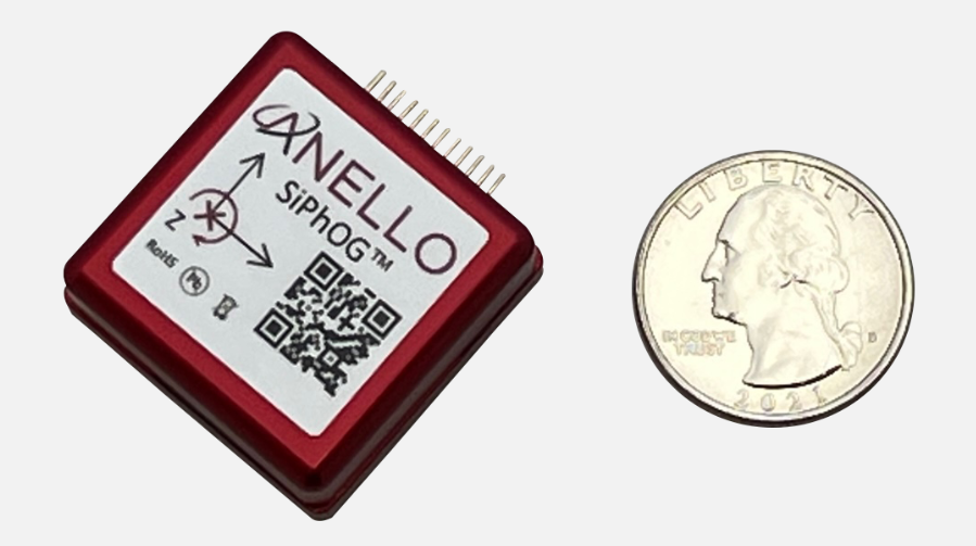
Anello is creator of the Silicon Photonics Optical Gyroscope (SiPhOG). By combining SiPhOG-based inertial navigation with advanced sensor fusion and AI-driven collaborative autonomy, Anello and Mythos AI are delivering a fully integrated, plug-and-play solution that maintains performance when satellite signals are degraded or unavailable. It is designed to drop seamlessly into both next-generation and legacy maritime platforms. A multi-mission open systems architecture enables scalable deployment across defense, commercial and hybrid maritime operations.
Strategic focus on maritime autonomy and USVs
The initiative is particularly relevant to the rapidly evolving unmanned surface vehicle (USV) market. As USVs take on expanded roles in offshore energy, maritime security, hydrography, environmental monitoring and defense missions, complete end-to-end dependable navigation is essential to safe and effective operations.
A resilient, GPS-independent navigation capability enables:
greater operational assurance in GPS-denied or contested maritime environments
enhanced autonomy and mission continuity during signal disruptions
reduced integration complexity for OEMs and system integrators
scalability across a broad range of vessel sizes and mission profiles.
Anello and Mythos AI will collaborate with OEMs, integrators and end users to align the solution with evolving operational and regulatory demands.
Swift Navigation and Asensing have announced full compatibility between the Asensing NAV3120 high-precision GNSS positioning module and Swift’s Skylark Precise Positioning Service. Skylark is a cloud-based service that improves the accuracy of GNSS from several meters to a few centimeters.
The widespread deployment of connected and autonomous IoT systems — including smart delivery robots, UAVs, precision agriculture and logistics — demands reliable, centimeter-level positioning that performs consistently across diverse environments and at scale.
Swift’s Skylark Nx RTK, the highest precision variant of Skylark, leverages a proprietary atmospheric model to deliver continuous 1-2 cm accuracy across vast geographic areas, including Western Europe. The carrier-grade network eliminates the need for developers to manage base stations or switch between multiple correction providers, simplifying the deployment of high-precision outdoor robots at scale.
The seamless interoperability between Skylark Nx RTK and Asensing’s NAV3120 module provides customers with a highly reliable, centimeter-accurate solution packaged in a compact, automotive-qualified hardware module. Joint testing demonstrated this high performance, with the solution achieving a sustained 1.7 cm horizontal position error at 95% confidence during a 24-hour period, which significantly accelerates time-to-market for applications requiring the highest level of positioning integrity.
The NAV3120 is full-constellation and quad-frequency signal reception module engineered for demanding applications. Features include:
Automotive-grade. Complies with AEC-Q100 standards for integrated circuits used in automotive applications.
Extreme operating range. Sustains temperatures from -40°C to +105°C.
Compact design. Small size and standard 17 x 22 x 3.1 mm footprint, weighing only 2g.
Efficient power. Low power consumption of just 0.4W.
The integrated solution is available now for use for autonomous mobile robots, UAVs, fleet management, advanced handhelds and wearables, and precision agriculture.
Industry experts noted in our November 2022 issue that heavy equipment autonomy may be a distant future. However, the steady innovation in machine-control technology to get there is yielding substantial value. To drill deeper into those technologies, we interviewed additional industry experts with a focus on the key role of GNSS in such systems.
1D, 2D and 3D
There is currently a sharp growth in the adoption of 3D systems, according to Jordan Van Wie, product specialist with SANY America, a prominent manufacturer of construction equipment. “The fact is that many jobs are requiring this. They’re more efficient in their bidding process. They know exactly where they need to cut and where to fill — this means being more productive in less time.”
SANY America is based in Peachtree City, Georgia, where many of its construction equipment systems are manufactured, including the SY225C, a popular medium excavator.
The process of automating to the levels the operators desire is a matter of which sensors are added and how they sense the active geometry of the equipment in use.
For an excavator, SANY installs four sensors, then measures the machine, said Mukesh Selvaraj, product manager, medium and large excavators, SANY America.
“We know the distance between the bucket pin and the stick pin, up through the boom, and the angles on the sensors. We can compute in the system and report where the tip of the bucket is in relation to the body, and construct a 3D model in real time. This reporting can be as fast as 200 Hz.”
Among the machine-control systems implemented on SANY construction equipment are those from Hexagon | Leica Geosystems. Leica produces precision guidance and control sensors and systems for construction, agriculture and mining that are integrated onto various heavy equipment brands.
While 3D is becoming more popular, systems need to be scalable. Hexagon | Leica Geosystems has variants for different levels of guidance and automation, said Kert Parker, U.S. channel development manager for the company.
“For instance, if you start with our PowerDigger Lite, it has a control box, a display, a boom sensor, an angle sensor for the stick (which includes a laser catcher) and a 360° bucket sensor. This lets you know where the bucket tip is in relation to the model — call it a 1D system.” The cost of such a system might only be 5% or 10% of the cost of the machine on which it is installed — a modest investment for the productivity gains it can deliver.
To upgrade and run automatics, users could add a machine control panel and docking station with just 2D software. “That will give you a semi-automatic solution even on 2D. Then you can upgrade and add the GNSS receiver and antenna — or antennas — and 3D software to make it 3D, semi-automatic,” Parker said.
Two-thirds of the price of the base system is for the sensors on the boom, stick, bucket, the pitch and roll sensor, and the wires that communicate throughout the system, Parker explained.
“So, it’s completely scalable. You can start with a low-cost system upgrade to do GNSS fully and semi-automatic. We can automate any pilot-controlled machine, then we set the pressure. And when we sense the stick pressure, if the system is going automatic, then we automate the boom and the bucket.”
Third ‘D’ Options
“When you’re using something to give the machine a northing, an easting and a height at all times — that is when it becomes full 3D,” Parker said.
3D systems can be configured with a single GNSS receiver, with dual GNSS receivers, or off of a robotic total station. “The only difference between single and dual is that, with single, every time you move the machine you have to do a calibration swing, about 90° to get your heading again.”
“You can dig curves and complex designs working in 2D,” Van Wie said. “But every time you move the machine, you have to re-bench to a known reference, either by pinching with a bucket’s teeth, or hit the stick sensor that has an incorporated laser catcher. When you move the machine, you catch the laser beam again, and you use that for your known reference to dig back from the 3D model.”
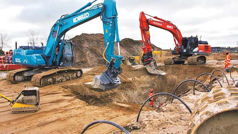
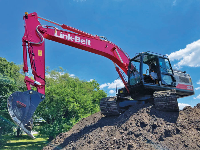
Excavators are a high-growth class of heavy equipment for machine-control adoption, with many excavators ready for system integration. Shown here, Leica iCON iXe3 systems on a Kobelco SK210 (left) and Hitachi 300-02 (right). (Image: Hexagon | Leica Geosystems)
For certain operations — such as excavating in a straight line or moving materials to the side —higher levels of automation may not be needed, so some users appreciate the option of starting with a cheaper system.
“For the small operator, of course, but even for a large operator, it’s a big investment to go full 3D,” Van Wie said. “They don’t want to go full 3D right away, or not on all equipment at once. They start off with just the basics and get familiar with it. Then when they want to upgrade, they have some of the stuff that they’re going to need for their machine already on it.”
System Examples
eSurvey GNSS manufactures GNSS-based equipment, software and systems for surveying, mapping, agriculture, UAV and construction. Better known in other global markets than in North America, the company has seen a steady rise in the market for construction automation — outpacing other sectors utilizing heavy equipment automation such as agriculture and mining combined. For construction, in many parts of the world excavators are the prime focus for automation.
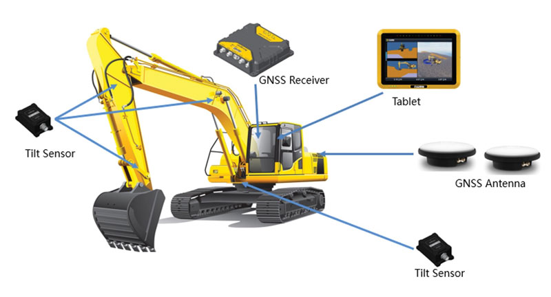
Figure 1. A common configuration of sensors for excavators: GNSS receiver, dual antennas, control tablet and tilt sensors on the body, boom, stick and bucket.(Image: eSurvey GNSS)
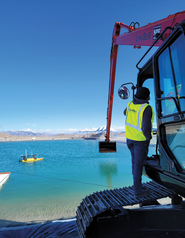
Their eME10 system for excavators includes a dual-antenna GNSS receiver, three single-axis tilt sensors, one dual-axis tilt sensor, a tablet and software (Figure 1). “The eME10 does not support a rotating bucket at this time,” said Edward Zhang, product manager for machine control technology. “We support standard excavators, excavators that reach into the water (for instance on dredging barges), and with different bucket tools such as quartering hammers and milling tools.”
Another popular system for compactors is the eMC10, with a single-antenna GNSS receiver, tablet and software, and optional temperature and vibration sensors.
Managing Positioning
Both the excavator and hydro survey boT have dual GNSS antennas for position and orientation, ensuring fidelity between the 3D model and operation of the excavator for dredging. (Image: Gavin Schrock)
High-precision GNSS, as implemented for architecture, engineering and construction (AEC) applications, can yield centimeter-grade results. However, as many AEC professionals and practitioners know, achieving repeatable and consistent results requires an experienced and skilled GNSS operator. Is the operator examining the results for statistical consistency? How have the observations been constrained to the desired reference framework? Have sources of error such as multipath and space weather been considered?
However, Nick Fifarek, general manager at SITECH Pacific LLC, a construction technology provider, said that equipment operators only need to learn the user interface.
“They are mostly concerned with how the grade is shown in the model, and what actions are required to meet the grade. They should not need to be concerned with the working of the GNSS receiver.”
A larger firm with multiple systems will usually have a technician or surveyor on board, Fifarek explained. This expert would have the experience needed to set up a GNSS site base, ensure corrections are received, and troubleshoot causes of anomalies and poor results.
To be efficient, an operator should not have to deal with a complex set-up.
“It should be more like Google maps in your car,” Fifarek said. “They do not need to know how the model was created, and how the GNSS delivers positions to the interface. All the sensors should work seamlessly, like tilt sensor and IMUs [inertial measurement units] and how they work together with the GNSS to put positions on the blade or bucket. Once this is all working well and the model is applied, they should just be able to take directions.”
Nevertheless, sometimes this expert will need coaching, or a small firm may not have an expert at hand.
“We may need to teach them about some fundamentals, such as signal-to-noise ratio, PDOP [positional dilution of precision], and other quality indicators — especially when setting up the site base station,” Fifarek said.
Additionally, he pointed out, the control must be set up — this is mostly done by engineering or surveying firms along with site calibrations — and operators need to know how to check it.
Multipath Issues. Fifarek has not experienced problems with short masts for GNSS antennas, saying that the height of the cab is sufficient. Modern multi-constellation receivers, have improved multipath mitigation, and are able to work in sites with limited sky view or obstructions. Equipment such as excavators and dozers typically have dual-antenna GNSS systems, or two receivers and antennas. This provides not only position, but orientation and heading. These are usually installed on the body or cab, although some systems have a GNSS antenna on each end of the blade. Some systems use a method that only fixes one of the antennas/receivers, and then performs a fixed baseline solution for orientation.
The Chain of Components
Much like autonomy in vehicles, machine control implementation can be defined as various levels.
Level 1: GNSS-assisted guidance. The most basic level of implementation provides the equipment’s location and heading. It acts the same way as a navigation device or phone in your car. The technology has been around for decades for precision agriculture and construction. Level 2: Implement Control. Control of the blade or bucket. Level 3: Assist. Implement control plus a level of automation where the operator moves the control stick to initiate an action the machine completes by moving the blade or bucket to meet the design model geometry. This can include steering for various types of equipment. Level 4: Autonomy. More on that later.
The power of tilt-compensated GNSS+IMU smart antennas may be the key to reducing the number and complexity of synchronizing a “chain of sensors.” In this example, a Trimble R780 smart antenna has been added to the stick of an excavator. (Image: Trimble)
For levels 2 through 4, continuously updating a position on the blade or bucket requires a chain of sensors to work in tightly controlled harmony. An excavator could be equipped with one or two GNSS receivers and antennas and a tilt sensor on the body, explained Geoffrey Kirk, product manager, autonomy and assist for Trimble. The GNSS will provide the position and orientation of the body, or rotating section of the body, on an excavator, and the tilt sensor reads how level it is. Another option is positioning with a total station and prism on the body, such as when GNSS is not available. “Either way, you need to know where you are in 3D space to be able to work on any 3D model,” Kirk said. “Today there are usually about 30 satellites in view. We can do so much more now compared to the days when we had fewer satellites, things that would have been impractical,” Kirk continued.
Sensors on the boom, stick and bucket can be likened to an upper arm (boom), forearm (stick) and hand (bucket), with rotating buckets acting like a wrist.
“We put a six-degrees-of-freedom IMU at each of these locations,” Kirk said. This is a chain of highly dependent geometry extended out to the bucket. However, Kirk said there may be a better way.
Reducing the Links
In recent years, a new technology has been implemented for GNSS smart antennas (rovers), like those that surveyors and grade checkers use, which tightly couples IMUs and movement of the GNSS antenna for calibration-free tilt compensation. Examples include the Trimble R12i (for surveying) and R780 (for construction), Leica GS19 T, and many more — few high-precision rovers made today lack tilt compensation. The observed acceleration and direction of the antenna adds orientation to the tilt angle (from the onboard tilt sensors), so the position of the tip of the survey rod can be computed precisely and in real time.
At the Bauma construction trade fair held in November 2022 in Munich, Germany, Trimble gave participants a peek at something new: putting a tilt-compensating GNSS smart antenna out on the stick of an excavator.
“With current systems, every time you hit one of those joints on an excavator, you need to understand what it is doing, calculating angles along the way,” Kirk said. “By mounting a tilt-compensated GNSS receiver on the stick, this becomes a lot easier to do.” Such innovations dovetail well with another trend in construction equipment: a move from purely hydraulic steering to drive-by-wire. This trend makes for more simplified and often less costly processes for adding implement control and automatics, but may also be key in implementing autonomy.
The Path Toward Automation
“One of the big changes in the industry is understanding what tasks operators are trying to do, so that we can help them do those tasks,” said Kirk. “We want to help people be more productive. We know autonomy is a thing. We’re actively working on autonomy; it’s going to be a while. In the interim, we want to make sure that we are providing value to the manual operators for the tasks that we can’t do autonomously.”
Key foundational components of what would go into autonomous systems are already in place.
“With automatics, you already have implement control, and in some implementations, you even have steering,” Kirk said. “What is missing in terms of the mechanics is speed control — that may be the easy part.” Adding the crucial situational awareness, other sensors for feedback, and the brains for automation is what might take a lot of time to work out.
“Autonomy for cars is where you are trying to avoid hitting things,” said Kirk. “For construction, we are in the business of hitting piles of dirt and spreading them around.” For a car, the sensors see something, recognize it, know how far away it is, and can issue such commands as “stop” or “slow down” — which is not so simple for construction.
Three key technologies you’ll see being used for situational awareness are radars, cameras and lidar, mostly used in combination. “Radars have some really nice behaviors,” explained Kirk, but cautioned that they cannot tell what they are doing.
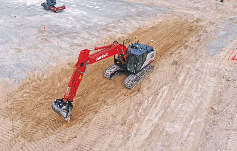
A demonstration implementation of an autonomous excavator.(Image: Trimble)
For instance, adaptive cruise control in cars, which is nearly always done with radar, works very well and reliably. Most such radars are now solid state and safety certified. Unfortunately, he points out, while radar is very good at alerting drivers that there is something in front of them, it is not very good at telling them what it is.
“That’s why developers put in cameras, so that you can see whether what’s in front of you is a person, another vehicle, or something else. That’s why you have those combinations of sensors.”
One of the reasons it will take longer to automate construction, Kirk explained, is that operators need to know much more about the nature of other objects in the construction environment than cars do on the road. The operators need to know not only what people, equipment and materials are around them, but also whether there is something or someone standing in front or on top of the pile of dirt.
“For situational awareness, you need to be able to do real-time mapping,” Kirk said. “Lidar and cameras, such as stereographic cameras, can be used as classifiers. Lidar can have limitations, such as when driving directly into the sun.”
“The smarts for autonomy are knowing what the task is and how to perform that task,” Kirk said. “However, from the standpoint of a machine’s sensor and setup, we’re not controlling speed, though we do on agricultural machines. So, machines are matched really well for autonomy — you can make them do whatever you want today.”
Examples of autonomous conduction systems were demonstrated in the off-site “sandbox” exhibit of Trimble Dimensions+ held in November 2002 in Las Vegas. There was an autonomous excavator, a compactor and a remote-control dozer.
Yet these were operating in a controlled environment. Kirk said that for safety reasons, early adoptions of autonomy might be confined to sites that are not along roads and highways.
Vai Photonics was founded in Canberra in 2021 by physicists Lyle Roberts (left) and James Spollard to commercialize their research at Australian National University. ANU Vice Chancellor Brian Schmidt is at right. (Photo: Vai Photonics)
Advanced Navigation has acquired Vai Photonics, a spin-out from Australian National University (ANU) developing patented photonic sensors for precision navigation.
Vai Photonics’ vision, to provide technology to drive the autonomy revolution, is similar to Advanced Navigation’s. It will join Advanced Navigation in commercializing its research into autonomous and robotic applications across land, air, sea and space.
“The technology Vai Photonics is developing will be of huge importance to the emerging autonomy revolution,” said Xavier Orr, CEO and co-founder of Advanced Navigation. “The synergies, shared vision and collaborative potential we see between Vai Photonics and Advanced Navigation will enable us to be at the absolute forefront of robotic- and autonomy-driven technologies. Photonic technology will be critical to the overall success, safety and reliability of these new systems.”
James Spollard, CTO and co-founder of Vai Photonics, explained the technology. “Precision navigation when GPS is unavailable or unreliable is a major challenge in the development of autonomous systems. Our emerging photonic-sensing technology will enable positioning and navigation that is orders of magnitude more stable and precise than existing solutions in these environments. By combining laser interferometry and electro-optics with advanced signal-processing algorithms and real-time software, we can measure how fast a vehicle is moving in three dimensions. As a result, we can accurately measure how the vehicle is moving through the environment, and from this infer where the vehicle is located with great precision.”
The technology, in development for more than 15 years at ANU, will solve complex autonomy challenges across aerospace, automotive, weather and space exploration, as well as railways and logistics.
Aircraft with an electric vertical-takeoff-and-landing system such as flying taxis will greatly benefit from this technology, according to Advanced Navigation. Landing and takeoff are often considered the most dangerous and expensive part of a flight route. Vai Photonics sensors will provide safe and reliable autonomous takeoff and landings under all conditions.
Space travel and exploration is fraught with risks, vast complexity and enormous cost. This technology will bring massive benefits to space missions, helping to cement Advanced Navigation as the gold-standard for space-qualified navigation systems for space exploration.
“The work that underpins Vai Photonics’ advanced autonomous navigation systems stems from the search for elusive gravitational waves — ripples in space and time caused by massive cosmic events like black holes colliding,” said Brian Schmidt, vice-chancellor of ANU. “The team have built on a decade of research and development across advanced and ultra-precise laser measurements, digital signals and quantum optics to build their innovative navigation technology.”
Abstracts for the ION GNSS+ 2022 show, “GNSS + Other Sensors in Today’s Marketplace,” are due March 4.
The ION GNSS+ conference will take place September 19-23 at the Hyatt Regency Denver at Colorado Convention Center in Denver. The show will also include a virtual option.
The 2022 conference will bring together international leaders in GNSS and related positioning, navigation and timing fields to present new research, introduce new technologies, discuss current policy, demonstrate products and exchange ideas.
The two tracks covered during the conference will be commercial and policy tracks and research tracks.
The commercial and policy tracks will include high performance and safety critical applications, status and future trends in GNSS, and mass market and commercial applications. The research tracks will include multisensor and autonomous navigation, algorithms and methods, and advanced GNSS technologies.
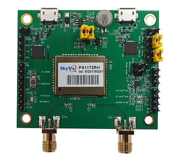
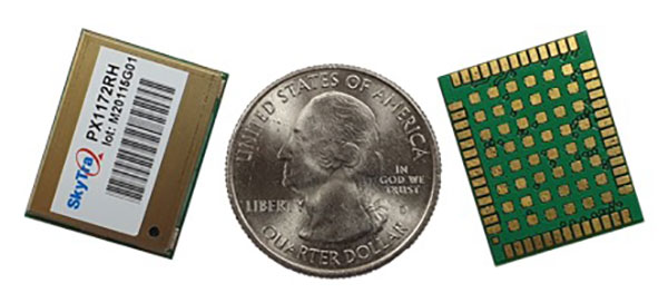
SkyTraq is offering a new multi-band, multi-GNSS receiver module for real-time kinematic (RTK) positioning and heading applications, suitable for autonomous vehicles. The PX1172RH surface-mount receiver measures 17 x 22 mm, about the size of a postage stamp.
With dual-antenna input, the PX1172RH receiver delivers sub-degree heading and pitch or heading and roll angles on top of centimeter-level positioning under both dynamic and static conditions. This removes the dependency on vehicle movement to initialize an inertial measurement unit (IMU) for attitude determination.
The PX1172RH is unaffected by magnetic surroundings and does not require calibration. It offers higher heading reliability and performance than magnetic heading sensors or single-antenna GPS sensors.
Photo: Skytraq
The PX1172RH works with dual-frequency GPS/QZSS L1/L2, GLONASS L1/L2, Galileo E1/E5 and BDS B1/B2 GNSS signals concurrently to enable robust positioning and heading performance under challenging partial-sky environments and to provide RTK convergence in seconds. The PX1172RH is suitable for autonomous precision-guidance applications.
A PX1172RH sample, datasheet and evaluation boards will be available in May, with mass production scheduled for June.
Abstracts for the ION GNSS+ 2021 show, “GNSS + Other Sensors in Today’s Marketplace,” are due March 5.
ION GNSS+ 2021 will be held Sept. 20-24 at the St. Louis Union Station Hotel. The show will also include a virtual option.
The 2021 show will feature in-person presentations with video presentations for remote viewers. It’ll also cover two tracks: commercial and policy tracks, and research tracks.
The commercial and policy tracks will include high performance and safety critical applications, status and future trends in GNSS, and mass market and commercial applications. The research tracks will include multisensor and autonomous navigation, algorithms and methods, and advanced GNSS technologies.
Authors whose abstracts are accepted in these sessions (either as a primary or as an alternate presenter) will have the option to have their papers peer-reviewed.
A German research team successfully demonstrated a completely autonomous airplane landing in May, without assistance from any ground-based systems, fulfilling a key step towards autonomous air traffic and the much-bruited Urban Air Mobility (UAM).
An optical reference system, encompassing a camera in the normal visible range and an infrared camera for conditions with poor visibility, combined with GPS to bring the modified Diamond DA42 in for a safe, unpiloted landing at the Diamond Aircraft airfield in Wiener-Neustadt, Austria.
The team, from the Technical University of Munich (TUM) and the Technische Universität Braunschweig, formed the project they call C2Land with funding from the German federal government. Two 2019 conference papers by the researchers, cited at the end of this article, give the technical underpinnings of the C2Land system.
What’s New
Automatic landings by both commercial aircraft and small planes can and do take place at major airports with the Instrument Landing System (ILS) infrastructure to guide aircraft in with sufficient precision. Ground antennas send radio signals to the autopilot to make sure it navigates to the runway safely. Procedures in development to use GNSS alone to make autonomous landings also require a ground-based augmentation system.
But systems such as these are too expensive for small airports that will conceivably carry the major share of UAM: automated air freight transport and autonomous flying taxis.
What needs to happen before George Jetson air taxis become a reality? UAM will take place in the zone 500 to 5,000 feet above ground, transporting one to five passengers or cargo over distances of five to 50 miles. The vision shared by most UAM stakeholders, a group that includes NASA and the FAA, involves vertical take-off and landing rather than conventional “glide” takeoff and landing, but precise navigation to the landing spot is critical in both cases.
“Automatic landing is essential, especially in the context of the future role of aviation,” said Martin Kügler, research associate at the TUM Chair of Flight System Dynamics.
Fly-by-wire systems, semiautomatic and typically computer-regulated systems for aircraft navigation, use GPS signals for positioning. But since GPS is susceptible to errors, interference, and obstruction, it is not solely sufficient for landing procedures. Current GPS approach procedures require that human pilots resume control over the aircraft at 60 meters altitude, and land the aircraft manually.
To enable completely automated landings , the TU Braunschweig team designed an optical reference system: two cameras, one in normal visible range and one infrared camera for poor visibility conditions. Custom image processing software lets the system determine where the aircraft is relative to the runway based on the camera data it receives. Additional functions were integrated in the software, such as comparison of data from the cameras with GPS signals, calculation of a virtual glide path for the landing approach and flight control for various phases of the approach.
Visual Recognition
Test pilot Thomas Wimmer, who sat through the procedure with his hands folded, said “The cameras already recognize the runway at a great distance from the airport. The system then guides the aircraft through the landing approach on a completely automatic basis and lands it precisely on the runway’s centerline.”
The researchers presented their system in two papers at the Institute of Navigation’s 2019 Pacific PNT Meeting in April:
“Model-based Threshold and Centerline Detection for Aircraft Positioning during Landing Approach,” by S. Wolkow, M. Angermann, A. Dekiert, and Ulf Bestmann; and
“Linear Blend: Data Fusion in the Image Domain for Image-based Aircraft Positioning during Landing Approach,” by M. Angermann, S. Wolkow, A. Dekiert, U. Bestmann, and P. Hecker.
Dime-sized INS with RTK paves the way for high accuracy in mass-market consumer applications.
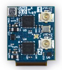
Photo: Inertial Sense
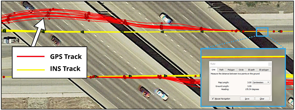
Inertial Sense has released a new micro-sized inertial navigation system (INS) with precise real-time-kinematic (RTK)-level accuracy. The company says the new solution paves the way for high accuracy in mass-market consumer applications.
The new micro INS with RTK solution offers an accuracy of 2-3 centimeters using GPS positioning in combination with inertial sensors (including on-board sensor fusion).
Inertial Sense designs and manufactures precision INS+RTK GPS sensors that deliver fast, accurate and reliable altitude, velocity and position for a wide range of autonomous vehicle applications, the company said.
The new micro INS with RTK provides a high degree of precision for orientation and GPS in a tiny package. Standard INS/GPS sensors offer accuracy in the range of 1.5 to 2 meters. Inertial Sense’s micro INS with RTK offers accuracy of 2-3 centimeters.
In the image above, a vehicle travels under an overpass. The 3-cm accurate RTK-inertial navigation track holds true to the vehicle’s position while the standard GPS signal is lost. (Image: Inertial Sense)
“The incredibly small size of our new micro INS with RTK sensor, in combination with its extremely affordable price point, will make this type of highly sophisticated technology accessible for general consumer applications for the very first time,” said Walt Johnson, founder and CTO, Inertial Sense. “We are offering RTK at a size, accuracy and price point that the market has never seen before.”
By optimizing the manufacturing processes for high volume applications, the micro INS with RTK sensor is as small and lightweight as a dime, and is available at a low price point.
Sensor fusion. Sensor data from MEMs gyros, accelerometers, magnetometers, barometric pressure and u-blox GPS/GNSS are fused to provide optimal position estimation. Data out includes angular rate, linear acceleration, magnetic field, barometric altitude and GPS time.
The miniature module provides orientation, velocity and position. Base station corrections data can be applied to achieve centimeter-level precision.
Autonomous vehicles. The sensor will enable the navigation of all types of autonomous vehicles with a very high degree of precision, Inertial Sense said.
Inertial Sense patented modules are currently being sold worldwide at volume for a broad variety of applications including:
Aerial surveys: UAV Payloads for 3D mapping, photogrammetry, orthomosaics
Gimbal stabilization and antenna pointing
3D motion capture and personnel tracking
Evaluation kits. Inertial Sense has bundled evaluation kits it says are simple to use and contain everything needed to begin logging RTK-accurate data. The evaluation boards can be utilized in both rover and base station configurations and include 900-mhz radios with onboard logging capabilities.
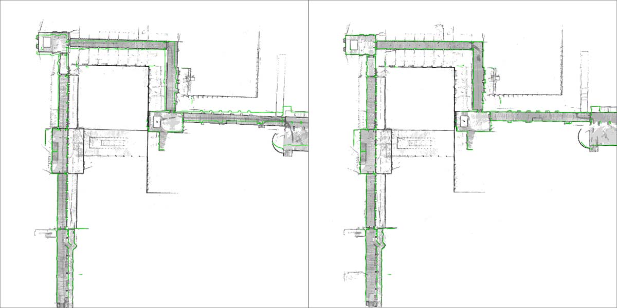
NavVis, a mobile indoor mapping, visualization and navigation company, released new mapping software that significantly improves the accuracy of simultaneous localization and mapping (SLAM) technology in indoor environments, such as long corridors, the company said.
The software update will be available for users of the NavVis M3 Trolley and will significantly improve the accuracy of the resulting maps and point clouds. NavVis’ mobile mapping system, the M3 Trolley, builds upon SLAM to increase speed and efficiency when scanning buildings.
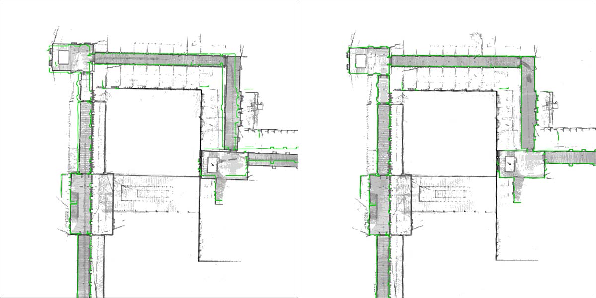
The images below demonstrate the impact of NavVis Precision SLAM technology. The left image depicts a long corridor mapped with a conventional SLAM system where the above-mentioned drift error has occurred. The green outline shows how the map deviates from the true structure. The image on the right shows the significantly improved map accuracy obtained when mapping the same area using the M3 Trolley with the new Precision SLAM technology.
Image: NavVis
Here is a closer look:
Image: NavVis
SLAM is a technique originally developed by the robotics industry that is now increasingly being used in surveying and autonomous driving technologies. It solves a core problem that long plagued robotics engineers by enabling a device to determine its location while simultaneously mapping an unknown environment. This is done by chaining millions of measurements into a trajectory estimate.
However, even when a device captures highly accurate individual measurements, chaining them will result in an accumulation of noise and tiny measurement uncertainties. Over time, the estimated motion will start to deviate from the true motion (drift error). This can often be observed as a slight bending of long corridors that are actually straight. All available SLAM systems — regardless of whether these use LIDARs or other sensors — are inherently affected by this phenomenon.
The NavVis Precision SLAM technology significantly reduces drift error and improves the SLAM accuracy. This is particularly evident in cases where complementary techniques such as loop closures cannot be deployed, if, for example, the building’s layout does not allow for it.
Precision SLAM even improves accuracy when SLAM anchors are used to incorporate ground control points into the mapping process.
“I am very excited about our new Precision SLAM technology,” said Stefan Romberg, head of mapping and perception at NavVis. “We are always striving for the highest possible map and point-cloud accuracy and improving SLAM is a critical component to being successful. It is widely known among SLAM developers and users that complementary approaches such as loop closures or ground control points are needed to achieve a high accuracy.
“However, with the Precision SLAM technology we have developed an approach that not only nicely complements the former techniques but is especially evident when these have little effect or cannot be used.”
Telit has announced the commercial availability of the SL869-3DR, a GNSS module for global use that leverages information from internal gyros, accelerometers and a barometric pressure sensor to perform dead-reckoning navigation for application areas such as track and trace and in-vehicle systems.
The module delivers accurate position data either directly from its multi-constellation receiver or from a fully autonomous dead-reckoning system, requiring no connections to external devices or components other than an antenna for satellite signal reception and power.
The module allows integrators to design zero-installation, in-vehicle navigation and tracking devices for fleets and other commercial or consumer applications that operate perched on the dashboard, connected only to vehicle power.
The SL869-3DR is a flash-memory based module capable of tracking three constellations simultaneously. The module integrates an array of micro electromechanical systems (MEMS) designed to provide it seven degrees of freedom. The innovative design of the internal sensor array in conjunction with the Telit MEMS-only Dead Reckoning (MoDR) software and intellectual property, deliver the host device unparalleled portable, turnkey dead-reckoning performance.
The Telit MoDR solution ensures that reliable position, velocity and time information is constantly available to the host application even when GNSS coverage is compromised, without the need for connection to the vehicle for wheel-ticks for speed or reverse-gear data. Its standard footprint lets navigation and tracking system integrators reuse existing device designs, eliminating complexity from external sensors and other apparatus, getting to market quickly with updated designs or product innovation.
“A significant number of the millions of commercial vehicles and fleets on the roads today are still operating with no or unreliable navigation systems because installation costs to connect the device to vehicle sensors are too high and require very specialized skills,” said Felix Marchal, executive vice president of GNSS and Short Range Wireless. “With the SL869-3DR we overcome that barrier because it enables devices that you simply connect to vehicle power and go. Up until now, ‘power-and-go’ navigation systems have largely relied on open-sky visibility, which is not typically where most commercial fleets operate. They are moving through tunnels, urban canyons and other environments where these systems cannot produce a position solution. Reliable MEMS-only dead reckoning, or MoDR as we call it, relies on very complex mathematical modeling and expert design of the sensor array. Developers must therefore, thoroughly scrutinize performance of the different products in the market. I am delighted that the SL869-3DR has outperformed competing products in its class across a wide range of test cases.”
The SL869-3DR is designed to support GPS, QZSS, GLONASS, Beidou and is Galileo ready. Telit MoDR technology boosts position accuracy in areas with adverse satellite reception conditions like urban canyons, overhead foliage, tunnels and parking garages. It integrates an embedded array of sensors including accelerometers, gyroscopes and a barometer (pressure sensor).
An antenna ON, antenna sense (open / short circuit) feature, allows the host application to inform the user of problems with the connection to the external antenna. An additional LNA delivers better sensitivity in harsh environments, better enabling devices with integrated antennas. The module also features fast calibration and is pin-to-pin compatible with the SL869, SL869-V3 and SL869-ADR.
Below is a video where performance the autonomous SL869-3DR MoDR is compared with the SL869-ADR automotive navigation module connected to vehicle sensors (wheel ticks and reverse signal).
Sensonor AS is partnering with NASA to supply current and future low- and near-Earth orbit space missions with inertial and gyroscope modules.
The Norway-based company first began supplying its standard inertial measurement unit (IMU) and gyroscope modules for low Earth orbit (LEO) space applications in 2012, beginning with the launch of the NASA-sponsored AeroCube-4 satellite. Sensonor’s STIM300 and STIM210 inertial products are now a standard part in many spacecraft similar to the AeroCube-4.
Current NASA projects using STIM inertial systems include the Raven technology demonstration and Near Earth Asteroid (NEA) Scout.
Raven, which launches to the International Space Station in September, will test key elements of an autonomous relative navigation system. Its technologies may one day help future robotic spacecraft autonomously and seamlessly rendezvous with other objects in motion, such as a satellite in need of fuel or a tumbling asteroid.
The concept image above shows the NEA Scout CubeSat with its solar sail deployed as it characterizes a near-Earth asteroid. (NASA)
The NEA Scout is a robotic reconnaissance mission that will be deployed to fly by and return data from an asteroid representative of NEAs.
NASA, in conjunction with the Aerospace Corp., spearheaded the use of STIM products in space, and many other commercial launch and satellite companies have since followed NASA’s lead. In fact, more than 30 companies around the world use Sensonor inertial products in various space applications, with several satellites successfully flying with STIM gyroscope modules for over three years.
The STIM gyroscope modules are often used in combination with GPS or a Star Tracker and Kalman Filter to orient and stabilize the satellite, as well as to provide feedback on satellite motion induced by its reaction wheels. In some applications, the gyroscopes are used to stabilize satellite- to-satellite communications.
Being a supplier illustrates the trust NASA and others place in Sensonor, further solidifying the company’s role in this market. “We look forward to continuing to serve the international space community with our inertial offerings as standard commercial off-the-shelf (COTS) products. By serving the space market on equal terms with our other customers, we can help to reduce the cost of manufacturing and launching space payloads,” said Hans-Richard Petersen, Sensonor’s vice president of sales and marketing. “Our STIM products are the lowest size, weight, and power for their performance level in the market, with 5 to 10 times lower weight than the next-best alternative with similar performance. This makes them a very cost-effective and attractive solution.”
Sensonor will continue to improve its gyroscope module and IMU product performance and features, and is actively working with the space community to enhance its standard commercial-off-the-shelf (COTS) parts. Following the tremendous interest from the space community, Sensonor has initiated a space-optimized version of its STIM gyro module.