Tag: drift error

  • Coloring the map to reduce visual drift in GNSS-denied navigation

    Coloring the map to reduce visual drift in GNSS-denied navigation

    Visual localization is widely used as a low-cost solution for autonomous driving, robotics, and mobile navigation. However, monocular systems remain vulnerable to illumination changes, weak texture, occlusion, motion blur and long-term drift.

    Existing map-based methods can reduce that drift by aligning camera observations with a prebuilt global map, yet many still struggle with redundant computation, weak cross-modal matching between camera images and point clouds, and optimization errors in large-scale or repetitive scenes.

    The challenge is especially important for lightweight platforms that cannot afford onboard lidar, inertial measurement unit (IMU) and heavy computing. Because of these problems, deeper research is needed on camera-only map-based localization that can stay accurate, efficient and stable in complex real-world environments.

    Overview of the proposed camera-only map-based localization framework. (Credit: Satellite Navigation)
    Overview of the proposed camera-only map-based localization framework. (Credit: Satellite Navigation)

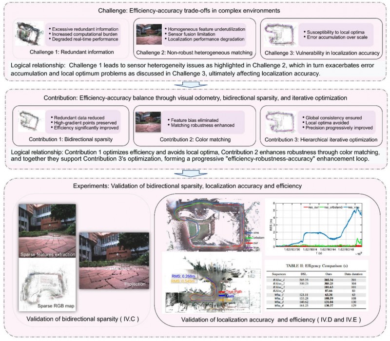
    On April 20, researchers from Wuhan University and Chongqing University reported (DOI: 10.1186/s43020-026-00196-x) in Satellite Navigation a camera-only localization framework that uses prebuilt colored point cloud maps, a dual-sparsity matching strategy that retains high-gradient features in both the map and image observations, and hierarchical geometric–photometric optimization to improve both positioning accuracy and computational efficiency in GNSS-challenged environments.

    The system is built around two connected stages. First, the researchers generate a sparse colored point-cloud map from a denser map produced by lidar–IMU–camera mapping, keeping only high-gradient points that preserve visually salient structures while removing weak or redundant information.

    They apply a similar sparse selection process to online camera images, creating what the team calls “dual-sparsity matching” between map and observation. During localization, the method uses Lucas–Kanade optical flow to track sparse 2D image features and associates them with 3D map points, while hidden-point removal helps retain only the map points actually visible from the current viewpoint.

    The pose is then refined through an iterated error-state Kalman filter in two stages: a geometric PnP-style correction for stable coarse alignment, followed by photometric refinement using image intensity consistency for sub-pixel accuracy.

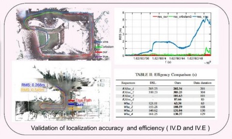
    Tests on the R3live and WHU-Motion datasets showed major gains over existing methods. Compared with direct sparse localization (DSL), the new approach cut absolute trajectory error (ATE) by 52% to 95% across challenging sequences, including a drop from 1.883 m to 0.152 m on R3live_5. It also improved accuracy by up to 76.6% over I2D-Loc++, reduced total processing time by as much as 47.7%, and remained robust in degenerate scenes where geometry-only localization deteriorated to 9.23 m while the proposed tracker held an ATE of 0.076 m.

    Ablation results further showed that colored maps, bidirectional sparsity, and hierarchical optimization each played a distinct role in achieving the final balance of speed, robustness, and precision.

    The authors said the main advance is not simply adding color to a map, but treating the global colored point cloud map as a continuous observation within the visual odometry framework. They said the framework shows that a monocular camera can localize far more robustly when paired with a prebuilt colored point cloud map and a coarse-to-fine optimization design that avoids poor local solutions.

    In their view, the study offers a practical middle ground between fully sensor-rich systems and fragile vision-only pipelines, preserving much of the accuracy benefit of map-based localization without demanding equally heavy hardware on the client platform.

    The work could have immediate value for indoor logistics robots, underground inspection platforms, warehouse vehicles, parking-garage navigation systems, and other low-cost autonomous agents operating where GNSS is weak or unavailable. Because the mapping can be completed offline and reused, the online platform needs only a monocular camera, which lowers sensing requirements while retaining strong global constraints.

    That makes the method especially attractive for scalable deployments in structured but challenging spaces such as tunnels, campuses, hospitals, and industrial facilities. More broadly, the study suggests that future navigation systems may become both lighter and more dependable by making better use of the information already shared between maps and images, rather than relying only on ever-larger sensor stacks.

  • RightPath designed to keep implements on track

    RightPath designed to keep implements on track

    Ag Leader has launched RightPath, a passive implement steering solution, to alleviate issues in precision agriculture resulting from drift.

    Putting the right seed in the right location with the right fertilizer is critical for farmers, and has led to the wide adoption of technology such as autosteer. However, if the pass-to-pass accuracy isn’t perfect at planting, the crop is vulnerable to damage in subsequent passes, which drags down yield.

    Trailed implements are known for drifting off the guidance line even when farmers use autosteer. The result is inaccurate placement of inputs and inconsistent guess rows. This is an issue because accuracy drives yield.

    Photo:
    RightPath is designed to operate seamlessly through Ag Leader’s InCommand Go displays. (Image: Ag Leader)

    A passive implement steering solution, RightPath keeps implements centered on the guidance line. This not only ensures precise input placement but also increases operational efficiency throughout the growing season, while minimizing crop damage, yield loss, and operator challenges.

    RightPath enables farmers to:

    • place the implement — and therefore rows and inputs — in the right place. 
    • plant seed accurately relative to a previous operation such as strip-till or NH3.
    • achieve consistent guess rows in all conditions including curves and uneven terrain.
    • re-use the same guidance line in the next field activity.
    • reduce stress and fatigue.

    RightPath is designed to operate seamlessly through Ag Leader’s InCommand Go displays. In addition, RightPath is compatible with both SteerCommand Z2 and SteadySteer, Ag Leader’s integrated and assisted steering solutions.

    While both the vehicle and implement require Ag Leader’s GPS 7500 to utilize RightPath, only the vehicle needs to be equipped with TerraStar-C, TerraStar-L or RTK. This gives an operator the flexibility to choose the right GPS correction for different operational needs.

    RightPath is available now through a single purchase unlock, with no recurring subscription fee.

  • OxTS: Meeting accuracy demands

    OxTS: Meeting accuracy demands

    Mobile mapping using an OxTS xNAV650 INS and lidar sensor. Photo: OxTS
    Mobile mapping using an OxTS xNAV650 INS and lidar sensor. Photo: OxTS

    We discussed mobile mapping with Jacob Amacker, application engineer, OxTS.

    How do you define “mobile mapping” as opposed to “surveying”?

    We use the two terms interchangeably. Each one has a different connotation depending on where you are in the world and both can be useful. We use them to cover a broad range of use cases, but “mobile mapping” is used more specifically for land-based mapping of the environment. A typical application might be a van equipped with an INS [inertial navigation system] and lidar sensors.

    “Surveying” can be used a bit more generally, applying to aerial or pedestrian-based mapping, but it does have the connotation of static mapping, which we do not typically handle.

    What are your main markets for mobile mapping?

    It is very hard to say. The world of mobile mapping is so diverse. However, lidar mapping could be seen as both the largest and the fastest-growing market in the surveying world as lidar has become widely affordable. Although our technology can be used with any surveying devices, at OxTS we particularly like to use lidar and are focusing on getting the best results from lidar data. This has included making our own point-cloud georeferencing software to maximize the potential of our navigation data in making point clouds.

    What are the main differences between your devices for aerial mapping and for ground-based mapping?

    We use the same INS device for both ground and aerial mapping. For use on manned aircraft, we would always recommend our highest accuracy system with the best IMU, the Survey+. The main source of inaccuracy in survey data will come from the IMU error over the range to the objects. Because most of this range is the aircraft’s altitude, this error is quite significant. For land-based mapping work, the measurements provided by the lighter and smaller xNAV650 are still suitable for many high-precision applications.

    GNSS-INS integration has been done for decades. What is new and what are the remaining challenges?

    It is now much more affordable to have very high-grade IMUs and GNSS receivers. Nevertheless, there will always be further improvements to be made to how the data streams are combined. On a similar note, other navigation aiding sources are increasingly being considered to supplement the IMU and the GNSS receiver — such as wheel speed sensors, lidar, camera odometry and others that can also be integrated to stabilize and improve the navigation data. Overall, it is very exciting what is yet to come out of INS technology. In recent years, it has become so good that people expect more and more from it, and this demand must be met. What happens when GNSS drops out? We are seeing increasing development to make the navigation data robust against challenges of any environment.

    Given the IMU’s drift, for how long can your system function at an acceptable level in case of a GNSS outage?

    It is difficult to put a number on what kind of drift is acceptable, as it depends on the application and the end-user requirements. Typically, half a meter of drift in one minute of GNSS-outage might be the goal for some of the higher-grade surveyors. Still others might only be satisfied with negligible drift.

    What keeps the INS and the lidar unit synchronized during a GNSS outage?

    The INS has an internal clock to keep the timing during a GNSS outage. Of course, this will not be as accurate as the atomic clocks on the satellites, but it is quite adequate to maintain survey-grade accuracy during GNSS outages. GNSS is still necessary to get the timing information in the first place, and this is a reliance that INS devices will want to remove in the future.

  • Tiny clock meets big challenges

    Tiny clock meets big challenges

    chip-scale atomic clocks can supplement GNSS receivers to provide accurate and reliable time in GNSS-challenged environments. Photo: Microchip Technology
    Chip-scale atomic clocks can supplement GNSS receivers to provide accurate and reliable time in GNSS-challenged environments. Photo: Microchip Technology

    Accurate and reliable time is just as important as accurate and reliable location for a wide range of military and civilian applications — and GNSS receivers cannot provide either one when they are jammed. For timing, one solution is to supplement GNSS receivers with a miniature atomic clock. We asked Microchip Technology a few questions about their chip-scale atomic clock (CSAC) and Stewart Hampton, the company’s senior product line manager, responded.

    How long was your SA65 CSAC in development before you announced it in August 2021? Typically, how often do you launch a new CSAC?

    CSAC development started in 2001 under a contract from DARPA with Draper and Sandia laboratories. CSAC was first introduced to the commercial marketplace in 2011, and in 2016 we released an improved product design with an operating temperature range of –10 C° to +70 C°. Last year we released our CSAC SA65 with a wider operating temperature range, faster warm-up and improved frequency stability aimed at the defense and industrial marketplace. So, it has been about five years between major CSAC releases, but that may not be indicative of future products because we have also introduced specialized CSAC versions, such as the Low Noise CSAC (LNCSAC) in 2014 and the only commercially available radiation-tolerant CSAC (Space CSAC) in 2018.

    What is the CSAC SA65’s drift rate?

    Its typical drift rate is specified at <9 × 10⁻¹⁰ per month. Another key specification, particularly for many portable military applications, is total sensitivity of frequency to temperature (tempco) over a specified range. For the CSAC SA65, that specification is ±3 × 10⁻¹⁰ over the entire operating temperature range of –40 C° to +80 C °.

    What are a few specific military use cases?

    CSAC is designed into multiple military programs and used in a wide variety of military applications, particularly in GNSS-denied environments — including assured positioning, navigation and timing (APNT) modules, underwater unmanned and autonomous vehicles, software-defined radios, man-portable transceiver-based military communications, vehicle management computers, airborne reconnaissance/UAVs and GNSS-disciplined oscillators. It is also used in command, control, communications, computers, cyber, intelligence, surveillance and reconnaissance (C5ISR). The space CSAC variant is commonly used on low-Earth-orbit space defense payloads supporting such applications as low-latency communications networks, RF geolocation (geointelligence, or GEOINT), optical time transfer, alternative PNT satellites and Earth observation.

  • NavVis improves SLAM precision indoors

    NavVis, a mobile indoor mapping, visualization and navigation company, released new mapping software that significantly improves the accuracy of simultaneous localization and mapping (SLAM) technology in indoor environments, such as long corridors, the company said.

    The software update will be available for users of the NavVis M3 Trolley and will significantly improve the accuracy of the resulting maps and point clouds. NavVis’ mobile mapping system, the M3 Trolley, builds upon SLAM to increase speed and efficiency when scanning buildings.

    The images below demonstrate the impact of NavVis Precision SLAM technology. The left image depicts a long corridor mapped with a conventional SLAM system where the above-mentioned drift error has occurred. The green outline shows how the map deviates from the true structure. The image on the right shows the significantly improved map accuracy obtained when mapping the same area using the M3 Trolley with the new Precision SLAM technology.

    Image: NavVis
    Image: NavVis

    Here is a closer look:

    Image: NavVis
    Image: NavVis

    SLAM is a technique originally developed by the robotics industry that is now increasingly being used in surveying and autonomous driving technologies. It solves a core problem that long plagued robotics engineers by enabling a device to determine its location while simultaneously mapping an unknown environment. This is done by chaining millions of measurements into a trajectory estimate.

    However, even when a device captures highly accurate individual measurements, chaining them will result in an accumulation of noise and tiny measurement uncertainties. Over time, the estimated motion will start to deviate from the true motion (drift error). This can often be observed as a slight bending of long corridors that are actually straight. All available SLAM systems — regardless of whether these use LIDARs or other sensors — are inherently affected by this phenomenon.

    The NavVis Precision SLAM technology significantly reduces drift error and improves the SLAM accuracy. This is particularly evident in cases where complementary techniques such as loop closures cannot be deployed, if, for example, the building’s layout does not allow for it.

    Precision SLAM even improves accuracy when SLAM anchors are used to incorporate ground control points into the mapping process.

    “I am very excited about our new Precision SLAM technology,” said Stefan Romberg, head of mapping and perception at NavVis. “We are always striving for the highest possible map and point-cloud accuracy and improving SLAM is a critical component to being successful. It is widely known among SLAM developers and users that complementary approaches such as loop closures or ground control points are needed to achieve a high accuracy.

    “However, with the Precision SLAM technology we have developed an approach that not only nicely complements the former techniques but is especially evident when these have little effect or cannot be used.”