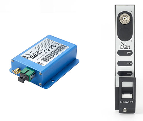
ViaLite GPS Link: Blue OEM module and rack chassis card hardware formats shown. (Photos: ViaLite)
ViaLite is supplying Raytheon Technologies with its GPS over Fiber Extension Kit for Microchip GPS servers. The kit provides mission-critical GPS timing and synchronization for systems requiring extremely accurate clock signals.
Standard transmission distances for the extension kit can be up to 10 km, while solutions are available for distances as long as 50 km.
“The ViaLite kit was chosen for its unique performance with Microsemi’s S650 timing server, along with our best-in-class quality, reliability and support,” said Craig Somach, ViaLite director of Sales North America.
The ViaLite GPS link is designed to provide a remote GPS/GNSS signal or derived timing reference to equipment located where no signal is available, such as inside buildings or tunnels. By using optical fiber instead of traditional coaxial cable, extreme distances are possible with no radio frequency loss and zero introduction of noise.
In a report issued on Jan. 14, the Department of Transportation (DOT) outlined the results of its GPS Backup Technology Demonstration project. As officials had previously projected, it called for a system-of-systems approach using multiple complementary technologies.
The report called for an architecture that included signals from space in the L-band, terrestrial broadcasts in the ultra high frequency (UHF) and low frequency (LF) spectra, and a fiber backbone to synchronize and feed precise time to terrestrial transmitters.
The demonstration project and report were mandated by Congress in legislation passed in late 2017 and funded in early 2018. Delays within the administration resulted in the project beginning in early 2019.
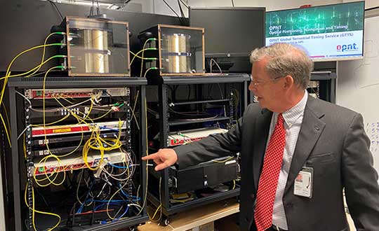
Monty Johnson of OPNT demonstrates precise time transfer through 100 kilometers of spooled fiber-optic cable. (Photo: RNT Foundation)
Demonstrations
Of 21 firms that offered to demonstrate their wares, 11 were selected. They were:
Echo Ridge LLC and Satelles Inc. Satellite-based PNT technologies using the S and L bands, respectively.
OPNT B.V. and Seven Solutions S.L. Fiber-optic time transfer using the White Rabbit Precision Time Protocol technology.
TRX Systems Inc. Dead reckoning technology with inertial measurement units and localized map matching supplemented with ultra-wideband beacons.
Hellen Systems LLC and UrsaNav. eLoran that uses LF transmissions.
Serco Inc. Medium frequency R-mode.
NextNav LLC. Metropolitan beacon system using UHF frequencies.
PhasorLab Inc. and Skyhook Wireless Inc. Both use Wi-Fi frequencies. Phasorlab uses a dedicated network of transmitters. Skyhook leverages existing Wi-Fi access points.
Five of the demonstrations were conducted at Joint Base Cape Cod, with the remainder at NASA’s Langley Research Center in Virginia.
Timing demonstrations were assessed for system:
coverage (service availability) within an “appropriate area” (wireless systems only)
accuracy and stability across an appropriate area
long-term accuracy and stability of time transfer to a fixed location
time transfer availability and accuracy to a fixed location under challenged GPS signal conditions.
Positioning was evaluated for:
coverage within a defined region
2D and 3D dynamic positioning service availability and accuracy
availability and accuracy of static positioning
long-term availability and accuracy of static positioning
long-term availability and accuracy of static positioning under challenged GPS signal conditions
DHS work referenced
The report also mentions an earlier set of demonstrations done by the Department of Homeland Security (DHS).
In December 2018, DHS’s Science and Technology Directorate performed the work through the Homeland Security Systems Engineering and Development Institute. The project “demonstrated a combination of position and timing use cases for dynamic vs. static and indoor vs. outdoor applications, along with a time-transfer use case for critical infrastructure applications.” Systems from Locata Corp, NextNav, and Satelles were evaluated.
The DoT report says that eLoran was not part of the DHS effort because of the lack of transmitters in the area. However, “DHS had previously studied eLoran performance under a Cooperative Research and Development Agreement (CRADA) with Harris Corporation and UrsaNav and had an understanding of its capabilities.”
A report of DHS’ December 2018 work is not publicly available, though DOT says it was used to inform their efforts.
The 437-page DOT report is filled to the brim with detailed information about the project, individual technologies, and demonstration results.
The Executive Summary says that, in addition to the findings from the DHS December 2018 effort (which were not listed), the DOT demonstration had four key findings:
All TRL-qualified vendors offered showed PNT “performance of value” and one showed value in all scenarios.
Neither eLoran company succeeded in the Static Basement Timing scenario.
R-mode ranging did not meet the minimum technical readiness level (TRL) of 6.
Deployment effort and coverage (infrastructure per unit area) are significant cost factors.
Addressing the needs of critical infrastructure owners and operators, the report concluded the needed “technologies are LF and UHF terrestrial and L-band satellite broadcasts for PNT functions with supporting fiber optic time services to transmitters/control segments.”
Reactions and way forward
Government officials and industry observers alike have welcomed the report, though it does leave some questions on the table.
One is about other national PNT needs. The congressional tasking was to report on GPS backup technologies for critical infrastructure and national security. The Jan. 14 report focuses on critical infrastructure needs. Information on national security requirements, some of which is classified, was provided to Congress separately by DHS and the Department of Defense.
“Economic and homeland security are sometimes considered by agencies and Congress as subsets of national security, sometimes not,” according to one analyst. “So, we don’t know if the needs of first responders, delivery services, civil government agencies, and other essential users were ever formally considered. The good news is that the combination of systems identified, if implemented and made available to all, would likely meet the needs of most.”
Other open issues are about implementing the report’s recommendations.
Some have been quick to point out that the demonstrations were to inform the government, not part of a procurement.
“If this was for an acquisition, it would have been done differently,” said one government retiree. “Rather than having vendors set up and operate the equipment, government evaluators would have been much more hands on. And they would have made every effort to do all the trials at the same location.”
Going forward, cost will also an important factor, as mentioned in the report’s key findings. “Depending on who you want to serve and where, the costs of different technologies vary by orders of magnitude,” said one provider.
Reaction from those involved with the demonstration project has been generally upbeat with praise for DOT’s effort and anticipation of more progress.
Typical were comments from Ganesh Pattabiraman, CEO at NextNav, who appreciated the real-world scenarios DOT used in the project. Regarding next steps he said, “We look forward to working with Congress on implementing the report’s recommendations.”
IQGeo, a developer of geospatial productivity and collaboration software for the telecoms and utility industries, has acquired OSPInsight International Inc., a U.S.-based leader in fiber-optic network management.
Under the terms of the agreement, IQGeo will purchase OSPInsight for $8.75 million, which will be funded through a mix of cash and shares. The completion of the acquisition is subject to shareholder final approval.
The OSPInsight fiber planning and design software for the telecoms market is highly complementary with IQGeo’s geospatial software that also supports telecoms network operations, according to a press release from IQGeo. While the current IQGeo offering targets larger enterprise network deployments (tier 1 and tier 2 operators), the OSPInsight software is ideally suited for the needs of smaller networks (tier 3 and tier 4 operators) with simple, fast deployments.
The combination of the two product lines, as well as the telecoms industry and software technology expertise, will enable IQGeo to service an expanded target market in existing and new geographies.
“The entire IQGeo team is very excited about the business and technology potential that will be created by the acquisition of OSPInsight,” said Richard Petti, CEO at IQGeo. “With more than 25 years of industry experience, they have developed an excellent product line and established an impressive list of customers, while building a very strong reputation in the telecoms industry. We see this as a fantastic opportunity that provides IQGeo with a proven software solution and sales channel for tier 3 and tier 4 network operators and it gives the OSPInsight team the global reach and financial resources needed to take their software to a wider audience.”
“The real winner in this acquisition will be OSPInsight customers,” explained Wade Anderson, CEO at OSPInsight. “Our customers will continue to enjoy the same level of support they’ve always had and have a greatly expanded product line for additional network management solutions. Existing and future OSPInsight customers will quickly have access to IQGeo’s industry-leading mobile software that digitizes field operations to improve network data quality and currency. The two product lines dovetail very nicely. I’m excited for the shared vision of providing world-class software that helps our telecoms customers transform their network operations. We can’t wait to get started.”
You can learn more about the acquisition by visiting the IQGeo Investor page to view a video interview with Richard Petti, IQGeo’s CEO and Haywood Chapman, IQGeo’s CFO.
The use of GPS signals is certainly commonplace in today’s technological age. Various locating systems, tracking systems and precision timing applications all use the common decoded NMEA and 1 PPS signals from a GPS satellite in a multitude of different ways.
When a direct line-of-sight path to GPS satellites is unavailable, the GPS signal must first be received where there is a direct line-sight path, decoded, and then the resulting signals routed to where they are needed. The Luxlink GPSX-1001 has been designed to do exactly that.
LuxLink GPSX-1001 fiber-optic transceiver.
The GPSX-1001 is the result of a specific request by a research group of a midwestern U.S. university for seismic studies in an underground mine. More than 20 units were installed in several branches of the mine and have been in continuous operation successfully for two years.
The GPSX-1001 transceiver is a multifunctional device that can be used as a transmitter or a receiver/repeater. In operation, the NMEA signal and the 1 PPS signal are both multiplexed by the GPSX-1001 (set as a transmitter) and launched into a single optical fiber. The multiplexed signal is then received from the fiber at a second GPSX-1001 set as a receiver/repeater. Here, the NMEA and 1PPS signal are de-multiplexed and available as individual outputs (see Figure 1).
FIGURE 1. GPSX-1001 block diagram.
The original multiplexed signal is also then reapplied to another integral optical transmitter for use at a third receiver/repeater. Additional receiver/repeaters can be connected in the same fashion to allow the signals to be transmitted to numerous locations.
Fiber-optic cable is virtually immune to electrical interference and can be routed wherever convenient without regard to the proximity of electrical noise producers, water or high voltages. Because fiber optic cable is non-conducting, ground loops that can result in loss or corruption of the GPS signals are virtually eliminated. The bandwidth of the fiber and circuitry in the GPSX-1001 is such that the fast rise and fall times of the 1-PPS signal are maintained and the NMEA signal is as noise free as the original input.
Transmission distances using the GPSX-1001 can extend to a mile or more. For longer distances, additional GPSX-1001 units can be added.
The GPSX-1001 is user configured by means of front-panel DIP switches. Integral LED indicators are provided to continuously monitor the NMEA, 1 PPS, power and optical link signals. Power is obtained from simple wall type plug-in adapters or low voltages and need not be regulated because the GPSX-1001 units contain internal regulators.
Figure 2 shows three GPSX-1001 units in a typical GPS signal distribution system. The NMEA interface can be RS-422 or RS-232, depending on the requirements of the signal source. The 1 PPS signal is 50-ohm TTL compatible. Each transceiver pair will produce signals over distances in excess of several miles and will operate from –35° to +75° C (–31° to 167° F), allowing them to be used both indoors and outdoors. Units are available for use with multimode or single-mode fiber and with standard fiber-optic connectors.
FIGURE 2. GPS NMEA/1 PPS transmission system.
Irwin Math is president of Liteway Inc. and has more than 30 years of experience in the design and development of fiber-optic transmission systems. He was also the founder of Math Associates Inc., one of the pioneering firms in fiber-optic transmission system technology in the early 1980s.
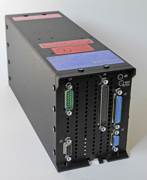
Northrop Grumman has been selected by AgustaWestland to supply the LCR-110 Inertial Reference System for the new AW609 TiltRotor aircraft.
Northrop Grumman Corporation has been selected by AgustaWestland, a Finmeccanica company, to provide flight-critical inertial instruments on the new AW609 TiltRotor aircraft undergoing civil certification through the Federal Aviation Administration.
The LCR-110 Inertial Reference System and the LCR‑300A Air Data Attitude Heading Reference System have been chosen as standard inertial navigation products for the advanced AW609 TiltRotor. The LCR‑110 features a high-performance, fiber-optic gyro-based inertial measurement unit and an advanced micro-electromechanical system (MEMS) triad accelerometer. The system offers hybrid navigation via GNSS data, in addition to aircraft autonomous integrity monitoring for GPS signal integration and integrity checks. These features are essential for precise Required Navigation Performance flight operations.
The LCR‑110 evolved from the successful, longstanding LCR‑100 product family that has been selected for numerous rotorcraft and fixed-wing platforms.
The systems were developed by Northrop Grumman Navigation and Maritime Systems Division’s subsidiary in Germany, Northrop Grumman LITEF.
“This suite of combined equipment provides critical flight control and navigation data to help the aircraft achieve required availability, precision and the highest levels of integrity,” said Eckehardt Keip, managing director for Northrop Grumman LITEF. “Our products enhance precision navigation operations, improve safety margins, save weight and volume, and provide attractive commercial advantages.”
The LCR‑300A is being introduced after several years of independent research and development. The system’s MEMS gyro provides advanced attitude heading reference system performance in combination with a magnetic sensing unit. It also features directional gyro mode, which minimizes magnetic compass errors.
The digital air data computer module, which is embedded in the LCR‑300A, was developed by Curtiss-Wright Corporation’s Defense Solutions division. It weighs less than 0.9 pound, yet contains the pneumatic sensors and processing electronics to generate the complete International Civil Aviation Organization air data parameter set. The module is designed using the latest high stability, low drift pressure transducer technologies, providing exceptional repeatability and reliability, Northrop Grumman said.
The twin engine, fly-by-wire AW609 TiltRotor combines the benefits of a helicopter and fixed-wing aircraft into one platform. The aircraft is a natural choice for civil and para-public roles, flying above adverse weather conditions at 25,000 feet in a comfortable and pressurised cabin at twice the speed and the range typical of helicopters.
The GPS Fiber Optic Distribution system from Optical Zonu connects up to 32 remote locations, transporting GPS signals from a single antenna to as many as 32 GPS receivers (or multiple antennas to multiple receivers). A common example of this application is a campus scenario where installing multiple GPS antennas is impractical. This particular system consists of the OZC J‐Series 5‐Slot modular 1U chassis. The Master Unit is located within close proximity of the GPS antenna and it contains modular and hot‐swappable fiber optic transmitter, AC power supply and J Optical Splitter cards. The remote unit is a stand‐alone (wall mountable) unit. It comes in a low profile semirugged package. A single 1U chassis at the master site is capable of supporting up to 32 remote locations.
The optical transmitter module has built‐in LNA for high sensitivity detection of low level GPS signals. The Master Unit also has a Bias‐T to provide DC power to the GPS Antenna. Local monitoring is also integrated into the Master Unit, which is accessible via a single computer interface terminal. The maximum RF input signal into the transmitter is ‐25 dBm and the RF interface is via a 50 Ohms SMA connector. The standard optical connector is SC/APC (FC/APC is also available upon request) for low back reflection applications. The system is designed to operate on single mode fiber but may be custom configured to work on multimode fiber. The system is configured for complete dual redundancy, including additional fiber optic Tx module for a second GPS antenna.