Other sources, such as lidar, can be used to aid navigation in the absence of GNSS signals. (Photo: OxTS)
We discussed complementary PNT with Peter Rylands, senior product manager at OxTS.
What are some of the most promising approaches to complementary PNT and how does simulation technology help?
There are two approaches of particular interest. The first is looking at LEO satellite systems that can provide supplementary and potentially more secure methods of navigation, with global coverage from a single system. But these will still suffer from some of the issues GNSS systems experience, namely, what happens when you can’t obtain a signal?
The second is the use of visual aiding through sensor fusion, such as lidar and cameras, that can provide relative positioning (or absolute positioning once you have a space mapped) using SLAM algorithms. While this may increase onboard hardware dependencies, it creates a localized navigation system that can be better protected from malicious actors.
In contrast, closed-loop systems can look to an infrastructure-based system, allowing free movement within the specific area in which the infrastructure is located and a potentially more reliable source of PNT, especially indoors, where GNSS is not available. Ultra-wideband is definitely the up-and-coming technology here, but systems using Wi-Fi, cameras, Bluetooth and others also are being used.
Simulation, as within many domains, allows users to test on a large scale with fewer barriers to entry than real-world testing and an ease in making iterative changes to find an optimal solution. Whether that is to benchmark performance in locations of interest or to change configuration settings to improve visibility or positioning, simulation allows you to do this without the expense of going straight into the environment itself or configuring the actual vehicle under test.
How does OxTS fit in that mix?
OxTS provides customers with the ability to navigate anywhere; whether for reference data in R&D, georeferencing for survey and mapping, or active navigation of autonomous solutions. To do this we provide an IMU-first offering that we then complement with other technologies. Traditionally, this is with GNSS, to form an INS that can provide centimeter-level accuracy. However, we are also aware of the vulnerabilities of GNSS. For us, this is when it becomes an unreliable source of PNT in denied areas, such as indoors, in urban canyons or under tree canopies.
Because of this, we are also investigating and developing complementary solutions that can enhance our offering for users who need confidence in their position even when GNSS is not available. Whether that is through sensor fusion, our Pozyx UWB solution for indoor navigation or other proprietary software and firmware capabilities.
What kinds of complementary PNT are most useful in addressing specifically the challenges posed by jamming and spoofing and how does simulation help?
We need to look at systems that cannot be impacted by, or have mitigations from, the impact of jamming and spoofing. Solutions that are independent of radio communications or satellite use are then valuable in providing this layer of protection. This is where we could look toward OxTS’s use of IMU technology and visual aiding systems. Simulation technologies would then allow you to run hardware-in-the-loop testing, where the primary GNSS solution can have simulated jamming and spoofing to understand the performance of your complementary and protected systems when GNSS cannot be trusted.
The OxTS Georeferencer combines INS and point-cloud data from third-party lidar sensors. (Image: OxTS)
OxTS is offering its new OxTS Georeferencer, a powerful lidar georeferencing software tool. OxTS Georeferencer combines OxTS inertial navigation data with raw lidar data to give surveyors the ability to create georeferenced point clouds along with tools to calibrate their setup and analyze the accuracy of their surveys.
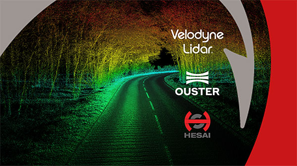
Users can now combine data from their OxTS inertial navigation system (INS) with a much broader range of lidar sensors. The OxTS Georeferencer works with pointclouds from Hesai, Ouster and Velodyne lidar sensors. New sensors brought to market can be quickly and easily added to OxTS Georeferencer.
This release ensures that surveyors can easily and confidently use OxTS Inertial Navigation Systems and OxTS Georeferencer, to produce georeferenced point clouds irrespective of the LiDAR scanner they prefer to use.
The OxTS Georeferencer gives surveyors flexibility in terms of the hardware they may use to survey their environment.
Users can combine OxTS INS data with data from the following models:
Velodyne. VLP-16 Puck, Puck LITE (beta), VLP-32C (beta) and Alpha Prime VLS128 (beta). The Velodyne VLP-32C sensor is single-return mode only.
Hesai. Pandar40P
Ouster. All Ouster Gen2 lidar, The OS1 and OS2 lidar with 32, 64 and 128 lasers (all Ouster integrations, other than the OS1-64 in uniform laser distribution, are in beta.)
Features of this release include:
Improved calibration. Take advantage of a broader range of set-ups without extensive planning and set-up costs. A data-driven calibration technique helps to get the best results from your set-up. It eliminates blurring and double-vision, especially at longer distances. The new version now can calibrate angles AND linear displacements. Please note that LIP calibration is in beta.
Error estimation. Gain more control over your point-cloud. The new pointcloud error estimation uses a sophisticated formula together with OxTS navigation data diagnostics. These are then used to estimate the centimetre uncertainty in point positions. Users can then choose a maximum uncertainty to be included or remove inaccurate points.
Dual return. Provide customers with enhanced point-cloud images. The new version of OxTS Georeferencer includes dual return capability for nearly all supported models. Where available, this will give point clouds much higher definition. Users can then present enhanced point-cloud images to customers and internal stakeholders as well as service specific applications.
Easily integration of new lidar families. This latest version of OxTS Georeferencer supports the future proofing of other new LiDAR sensors. It allows users to quickly and simply add new LiDAR families to the framework. If there are any LiDAR sensors NOT currently integrated that you want to see, contact OxTS and they will consider them.
For more information on OxTS Georeferencer or to arrange a demonstration, contact OxTS – OxTS Georeferencer.
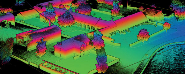
A point cloud is fundamentally a simple construct. It is a collection of points in 3D space, each point being given a coordinate in Cartesian convention. The points can also be given other properties, often these will be indicative of how they were obtained.
Examples might include the time at which they were “seen” by the surveying device that collected the data. The intensity or error in position that the point has might also be included.
Often point clouds will have around 100 million points after conducting a survey. Photography can also be overlaid on point clouds using photogrammetry techniques to essentially build 3D photography.
Image: OxTS
INS survey: point clouds
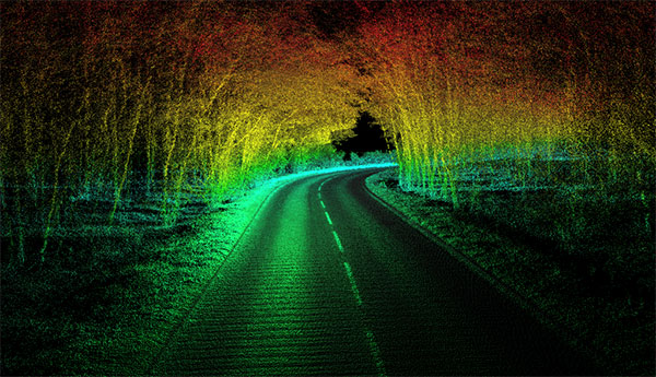
The principal method of collecting point-cloud data is by using lidar. Lidar technology is akin to radar: light is sent out from the device and bounces back off of objects. The difference is that radio uses large wavelength radio waves and lidar uses small wavelength lasers for high precision.
The time for light to return to the device is used with the speed of light to calculate the distance away. Typically, a lidar device will contain lasers with a fixed vertical angle, but which spin around in the horizontal plane. Internally, the device knows at what angle the laser is pointing vertically and its azimuth angle. This gives the device the position of the point on the object in 3D spherical coordinates.
The lasers inside produce thousands of points per second. Intensity, mentioned above, refers to the intensity of the reflected beam and indicates the reflectivity of the object.
What is a georeferenced point cloud?
Lidar requires navigation data to conduct a survey. We combine the navigation data with the lidar data to create georeferenced point clouds. Lidar devices know where points are in relation to each other, but they need to be told where they are in the world to be able to build a point cloud while moving the lidar.
The navigation data often comes from an inertial navigation system (INS). An INS is a sophisticated combiner of inertial measurement unit (IMU) and GNSS data to get the best navigation data — so a device knows where it is in the world and how it is moving.
The coordinates from the INS are added vectorially to the point coordinates of the lidar to get the final coordinates that would be used in the point cloud. This allows a user to put their lidar device on a vehicle like a van or an unmanned aerial vehicle (UAV) with an INS, to survey large areas efficiently instead of doing multiple static surveys and stitching them together.
Photo: OxTS
What are point clouds used for?
There are a wide range of applications for which point clouds can be used. They are increasingly used in real time for robots and autonomous driving computers to understand their environment and navigate through it. The data in a point clouds is convenient for recognizing and identifying surfaces and objects; for example, other cars, road signs and lane markings.
OxTS has been a global leader in inertial and GNSS technologies since 1998. OxTS is fundamentally involved in helping car manufacturers get the navigation data they require to go with lidar data in autonomous vehicle development, and in point clouds creation for use in surveying.
Distances and volumes are easy to calculate using point-cloud analysis software, and intensity can help identify different materials.
Another feature that lidar offers is multi-returns. This allows a laser pulse (which has a finite cross-section) to bounce back off of multiple surfaces to give multiple points from the same pulse. This is particularly useful for seeing windows and also seeing through them, and also for a myriad of other uses such as seeing the top of a treeline and the ground when flying over with a UAV.
It can also be used to see snow depth. The lidar can see the top layer of snow and also gets another strong return from the ground beneath.
At OxTS, we see lidar point clouds being used for driverless-car and work-vehicle development, coastal and forest management, infrastructure monitoring (signs, drains, bridges, road surfaces, railroads, etc.), creating 3D models of cities, pipeline exploration and more.
The final product is a simple file format, for which the possibilities are almost endless — and we see new applications using point clouds all the time.
SimActive Inc., a developer of photogrammetry software, has launched an automated solution for direct georeferencing from real-time kinematic (RTK) positioning.
Within the new workflow feature, users can achieve get high accuracy in projects without the use of ground control points (GCP), saving time in collecting and processing data.
Martin Instrument, a reseller of SimActive and surveying equipment, is benefitting from the automation. “Direct georeferencing greatly helps reducing cost for applications like corridor mapping,” said Mike Minick, vice president of sales at Martin Instrument. “The new automated option within SimActive software for direct georeferencing greatly facilitates the user workflow.”
“With RTK GPS available on drones, the use of direct georeferencing is growing within the industry,” said Louis Simard, CTO of SimActive. “Correlator3D allows users to maximize their hardware and software investment.”
For a live demonstration at the Commercial UAV Show (Nov. 15-16, London, United Kingdom), visit SimActive’s booth or send an email to [email protected].
SBG Systems Chief Technology Officer Alexis Guinamard discusses the company’s full line of inertial sensors at Intergeo 2016, which was held Oct. 11-13 in Hamburg, Germany. SBG Systems featured its mobile mapping, aerial survey and georeferencing solutions at the trade fair.
Geodata is key to the digital future and a 4.0 business world, according to a new report released at InterGeo in Hamburg, Germany. At the heart of this business vision is the networking of sensors that must have location data in order to fulfill their value.
The 116-page Intergeo Report, in parallel German and English, includes sections on smart cities, public participation, autonomous driving with live mapping, and surveying on the open seas. An eight-page GNSS Update section features CEOs answering questions market focus of their GNSS products, the role of geo-referencing in the Internet of Things, the coming-of-age of precise point positioning (PPP), and the opportunities for GNSS opened up by autonomous driving.
Access to company-specific geodata offers managers in the automotive industry a competitive ad- vantage. Apps show today’s motorists the way to the nearest electrical charging station. Soon, the same motorists will talk to their on-board computer to find a parking space. It will guide them instantly to the nearest free space. Geoinformation will then no longer just be found in the satnav but also in the integrated sensor in the road paving infrastructure and in the status reports of other road users.
Networking Everything. The Internet of Things is taking shape and permeating all areas of life. At its center are the tiny pieces of information that assign coordinates to a parking space, a loading berth for a container ship, a screw in the shelves of a supplier’s warehouse, or the alarm system of a family home. Degrees, minutes and seconds show people the way, answer a range of questions and help make informed decisions. Geoinformation is both an asset and an essential source of information.
Content Is King. Key companies in the geoinformation sector have naturally taken onboard the value of geoinformation. It forms the basis of their business activities. The use of geodata as added value for their products is still very new. Esri realized early in the sector that selling software is no longer sufficient on its own. Only data enables customers to harness the value of products. Cloud solutions store the mountains of data, while platforms deliver the answers.
Such new business leading lights as AirBnB, Uber, Facebook and Google could not survive without geoinformation. It is part of increasingly intelligent systems that make users’ lives a little easier and more comfortable, optimizing processes and enabling people to operate and participate in ways that were previously impractical or impossible.
The examples are myriad. Consider just a few. Digitally aided planning and construction in building information modeling not only streamlines processes and reduces costs, it enables public participation in planning procedures, using digital models of planned reality. Aerial surveys and data gathering by UAV, not only for traditional survey needs but for growing requirements in natural resource planning and management, infrastructure inspection and maintenance, surveillance and security, and more. Guidance systems for the blind.
All require location data. GNSS (satnav) is the core supplier of this data, but must be augmented by other technologies in special environments.
Releasing Geodata Pays Dividends. Managers of geodata realize they need to release it in order for it to lead them to “more” – more value, more benefits, more transparency, more importance. Geoinformation and digitization are inextricably interlinked, and this is just the beginning.
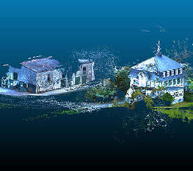
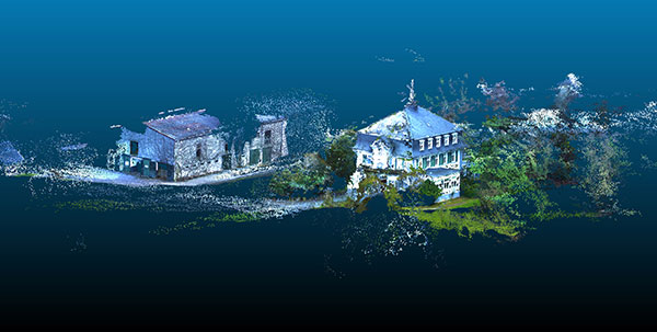
Four point clouds, nonregistered, of georeferenced images from four UAV flights.
By Christian Eling, Lasse Klingbeil, Markus Wieland, Erik Heinz and Heiner Kuhlmann
Direct georeferencing with onboard sensors is less time-consuming for data processing than indirect georeferencing using ground control points, and can supply real-time navigation capability to a UAV. This is very useful for surveying, precision farming or infrastructure inspection. An onboard system for position and attitude determination of lightweight UAVs weighs 240 grams and produces position accuracies better than 5 centimeters and attitude accuracies better than 1 degree.
Data acquisition from mobile platforms has become established in many applications recently, particularly using unmanned aerial systems (UASs). Unlike other mobile platforms, unmanned aerial vehicles (UAVs) can overfly inaccessible and also dangerous areas. Furthermore, they can get very close to objects to collect high-resolution data with low-resolution sensors, and they enable approach from all viewing directions without physical contact. UAVs now see use in precision farming for phenotyping or plant monitoring, and in infrastructure inspection and surveying.
Data acquisition from mobile platforms has become established in many applications recently, particularly using unmanned aerial systems (UASs). Unlike other mobile platforms, unmanned aerial vehicles (UAVs) can overfly inaccessible and also dangerous areas. Furthermore, they can get very close to objects to collect high-resolution data with low-resolution sensors, and they enable approach from all viewing directions without physical contact. UAVs now see use in precision farming for phenotyping or plant monitoring, and in infrastructure inspection and surveying.
This article addresses lightweight UAV use for mobile mapping and uses the term micro aerial vehicle (MAV) throughout. MAVs can generally be characterized as having a weight limit of 5 kilograms and a size limit of 1.5 meters.
We focus on the development of a real-time capable, direct georeferencing system for MAVs, since spatial and time restrictions often exclude the possibility of deploying ground control points for an indirect georeferencing. The demand for the real-time capability results from the aim to also use the georeferencing for autonomous navigation of the MAV and to enable a precise time synchronization of the onboard sensors. Furthermore, a real-time direct georeferencing also offers the opportunity to process collected mapping data during flight.
Mapping on demand. The goal of this research project, funded by the Deutsche Forschungsgemeinschaft (DFG), is to develop an MAV that can identify and measure inaccessible three-dimensional objects by use of visual information. A major challenge within this project comes with the term “on demand.” This means that apart from the classical mapping part, where 3D information is extracted from aerial images, the MAV is intended to fly fully autonomously on the basis of a high-level user inquiry. During the flight, obstacles must be detected and avoided. To extract semantic information that can be used to refine the trajectory planning, the mapping data has to be processed in real time. When the georeferencing information is used as initial values for the bundle adjustment, the image processing can be significantly accelerated.
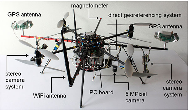
Figure 1 shows the current MAV platform developed in this project. We customized an MAV kit to a coaxial rotor configuration, replaced the centerplates with more stable carbon-fibre plates to stabilize the system, and installed the direct georeferencing and the mapping sensors. The two stereo camera pairs, pointing forward and backward, act as an additional sensory input for the position and attitude determination; the 5M-pixel industrial camera with global shutter is the actual mapping sensor. The PC board is used for onboard image processing, flight planning and machine control; the Wi-Fi module enables a connection to a ground station.
Figure 1. The MAV with mapping and georeferencing sensors, developed for the research project Mapping on Demand.
Although the direct georeferencing system must be small and lightweight, accuracy requirements for its position and attitude determination are high. Generally, these accuracy requirements are different for the machine control, navigation and mapping purposes.
In our project, the MAV is intended to maintain a safety distance of about 0.5 meter to obstacles. Hence, a position accuracy of 0.1 meter is sufficient for the navigation. The absolute attitude accuracy should be in the range of 1 to 5 degrees. For machine control, relative information is more important, and for this the accuracies should be slightly higher.
For mapping purposes, the positions and attitudes have to be known better, since the absolute georeference of the final product (for example, a high-resolution 3D model of a building) is based on the positions and attitudes from the direct georeferencing system. Therefore, the position accuracy should be in the range of 1–3 cm and the attitude accuracy should be better than 1 degree. The relative accuracy of the exterior camera orientation can be improved by a photogrammetric bundle adjustment, but systematic georeferencing errors should be avoided.
To summarize:
The weight of the system has to be less than 500 grams (g), to be applicable on MAVs.
Especially for the control and navigation, the system has to be real-time capable.
All sensors have to be synchronized and outages of single sensors should be bridgeable by other sensors.
The system is intended to provide accurate positions (σpos < 5 cm) and attitudes (σatt < 1 deg) during flights.
The integration of data from additional sensors, such as cameras, should be possible.
The ability to include additional sensors to the system was, apart from the size and the weight constraint, the main reason for developing a proprietary system instead of using a commercial unit with similar capabilities.
Direct Georefencing
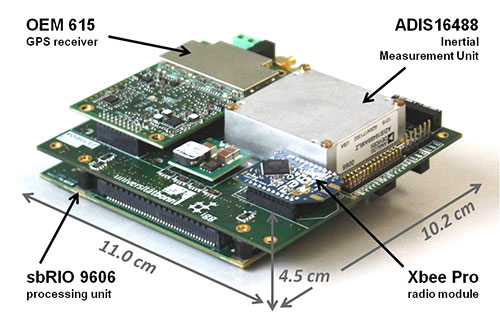
The current version of the system weighs 240 g without GPS antennas (see figure 2). To reduce weight, the antennas were dismantled, reducing their weight from 350 g to 100 g. However, since the antenna reference point got lost in this process, the antennas had to be recalibrated in an anechoic chamber for further use. By comparison to the original antennas, the dismantling led to significant changes in the phase center offsets (circa 4 cm in the Up, < 1 mm in the North and East component) and in the phase center variations (< 5 mm) of the antennas.
Figure 2. The direct georeferencing system.
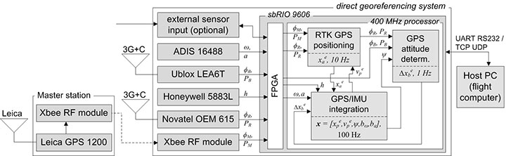
Figure 3 shows a flow chart of the direct georeferencing system with the sensors and the main calculation steps. The system consists of a dual-frequency GPS receiver, a single-frequency GPS receiver, an inertial measurement unit (IMU) and a magnetometer. The dual-frequency receiver is the main positioning device. Together with the GPS raw data from the master station (carrier phases ϕM, pseudoranges PM), which is transmitted via a radio module, the data of the dual-frequency receiver (ϕR, PR) is used for an RTK positioning, leading to centimeter position accuracies.
Figure 3. Flowchart of the direct georeferencing system.
In collaboration with the data of the single-frequency receiver (ϕB, PB), the data of the dual-frequency receiver is also used for GPS attitude determination. The corresponding GPS antennas of these two receivers form a short baseline (baseline length = 92 cm) on the MAV. The determination of the baseline vector in an e-frame (Earth-fixed) enables yaw and the pitch-angle determination.
The tactical-grade micro-electro-mechanical (MEMS) IMU, which includes three-axes gyroscopes, accelerometers and magnetometers, provides angular rates (ω), accelerations (a) and magnetic field observations (h) with high rates (100 Hz) for position and attitude determination. To be unaffected by the electric currents as much as possible, an additional magnetometer is placed on the outer end of one of the rotor-free MAV arms.
The direct georeferencing system further consists of a processing unit, which is a reconfigurable IO board, including a field programmable gate array (FPGA) and a 400-MHz processor. In this combination, the FPGA is used for fast parallel communication with the sensors. Afterwards, the preprocessed sensor data are provided to the 400-MHz processor via direct memory accesses, avoiding delays and supporting the system’s real-time capabilities. Finally, the actual position and attitude determination is carried out on the 400-MHz processor.
Methodologies
All position and attitude determination algorithms running on the system were developed in-house. Generally, the integration of these steps could be realized in one tightly coupled approach. Nevertheless, in the current implementation, we decided to separate the different raw data calculation steps, and we only use interactions at the level of parameters. This approach has the advantage that the integration is more reliable and more practical in the real-time programming.
GPS/IMU integration. In this calculation step, all available sensory input is fused to determine the best position and attitude of the system that is currently available. The GPS and the IMU measurements complement each other well, since the IMU provides short-term stable high-rate (100 Hz) data, and the GPS provides long-term stable low-rate (10 Hz) data.
The GPS/IMU integration can be separated into the strapdown algorithm (SDA) and the Kalman filter update. In the SDA, the high-dynamic movement of the system is determined integrating the angular rates and the accelerations of the MEMS IMU in real time. Because the SDA drifts over time, the long-term stable measurements of the magnetometer and the GPS receivers are needed to correct and bound the drift of the inertial sensor integration, which is realized in an error state Kalman filter.
In the GPS/IMU integration algorithms, the navigation equations of the body frame (b-frame) are expressed in an e-frame. Therefore, the full state vector x includes the position xep and the velocity vep, represented in the e-frame. For the attitude representation a quaternion q is used. Finally, the accelerometer bias bba and the gyro bias bbω are also estimated:
The observations in the measurement model are:
the RTK GPS position xea of the dual-frequency RTK GPS antenna reference point, expressed in the e-frame,
the GPS attitude baseline vector Δxeb, expressed in the e-frame,
the magnetic field vector hb, expressed in the b-frame.
Because the reference point of the RTK GPS antenna is not identical to the system reference point, a lever arm between the system and the antenna reference point must be regarded in the measurement model of the RTK GPS positions. From calibration measurements, the coordinates of the lever arm are precisely known in the b-frame.
In the SDA, a coupling between the accelerations, measured by the IMU, and the positions, measured by the RTK GPS, exists. Due to this coupling the yaw angle can be observed, but only in the presence of horizontal accelerations.
To determine an accurate and reliable yaw angle for every motion behavior, the short GPS baseline is realized on the MAV. A significant challenge in processing this baseline is the ambiguity resolution, because only single-frequency GPS observations can be used. Empirical tests have shown that the ambiguity resolution of a single-frequency GPS baseline generally takes several minutes. Among other strategies, we use the additional information from a magnetometer to improve the ambiguity resolution and to actually enable an instantaneous ambiguity fixing during kinematic applications.
Ferromagnetic material on the UAV and high electric currents of the rotors create significant disturbances of the magnetometer during flight. While the influence of the material can be compensated by calibration procedures, the influence of the dynamically changing electric currents are more challenging. To minimize them, the magnetometer is placed at the outer end of a rotor-free arm of the MAV. Also, the measurement model is arranged so that magnetic field observations only have an impact on the yaw determination in our algorithms.
RTK GPS Positioning. RTK GPS positions are calculated in real time with a rate of 10 Hz. These RTK algorithms are in-house developed, although commercial and open-source solutions are available. The main reasons for developing custom software are the following:
Integration of other sensors and/or solutions is possible, to improve ambiguity resolution and cycle-slip detection.
In commercial software, there is generally no access to the source code.
In the development of a real-time capable system, the software must meet the requirements of the operating system running on the real-time processing unit.
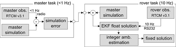
Generally, the RTK GPS algorithm complies with a single baseline determination (one master, one rover), where the master station remains ground-stationary and the rover is onboard the MAV.
To resolve the ambiguities and finally to determine the RTK GPS positions, the parameter estimation is performed in three steps: float solution, integer ambiguity estimation and fixed solution.
The float solution is realized in an extended Kalman filter (EKF). Beside the rover position, represented in the e-frame, the EKF state vector xSD also contains single-difference (SD) ambiguities N j on the GPS L1 and the GPS L2 frequencies. The reason for estimating SD instead of double-difference (DD) ambiguities is to avoid the hand-over problem that would arise for DD ambiguities, when the reference satellite changes.
To allow for an instantaneous ambiguity resolution, the observation vector l consists of DD carrier phases Φjkrm and DD pseudoranges Pjkrm on the GPS L1 and the GPS L2 frequencies.
In the current implementation, a random walk model is assumed as a dynamic model of the MAV in the EKF. Even if this is a simple model, it complies with the movement of the vehicle, when the process noise is chosen appropriately.
The float solution procedure provides real-valued ambiguities and their covariance matrix. These ambiguities now must be fixed to correct integer values, to fully exploit the high accuracy of the carrier phase observables. We applied the MLAMBDA method for integer ambiguity estimation.
Finally, a decision must be made whether or not the result of the integer ambiguity estimation can be accepted. This is done by the simple ratio test. With the ambiguities fixed, the final rover position xae is estimated with cm accuracies.
Usually, the time to fix the ambiguities with the algorithm takes a few epochs, but often the ambiguities can be fixed instantaneously. Once ambiguity resolution has been successful, the ambiguities can be held fixed, as long as no cycle slip or loss of lock of GPS signals occur.
Due to the GPS/IMU integration, we have a precise prediction of the RTK GPS positions between two epochs. Thus, the integration of the inertial sensor readings enables us to detect and also repair cycle slips very reliably.
The observations of the master receiver must be transmitted via radio to the direct georeferencing system. In practice, this data transmission can only be realized with a rate of 1 Hz. To be less dependent on this potentially unreliable master data transmission and the lower sampling rate, simulated master observations are used for RTK GPS position determination. Hence, in the actual processing, the true master observations are only used to update the simulation errors in the master task (figure 4), which have to be applied to correct the simulation results in the rover task.
Figure 4. Task scheduling of the RTK GPS algorithms.
GPS attitude determination. The GPS baseline is determined at 1 Hz. In contrast to the RTK GPS positioning, both antennas of the attitude baseline are mounted on the MAV, so that the complete baseline is moving. Furthermore, the baseline length is constant and known from calibration measurements. The GPS attitude determination also consists of the three steps: float solution, integer ambiguity estimation and fixed solution.
The float solution is also based on an EKF where the single-frequency SD ambiguities N j of the attitude baseline are estimated. Further parameters in the state vector are the baseline parameters and the first deviation of the baseline parameters.
As observations DD carrier phases ΦjkAB and DD pseudoranges PjkAB on the GPS L1 frequency are used. To improve the ambiguity resolution, the attitude from the GPS/IMU integration is added to the observation vector, by transforming the known b-frame baseline parameters into the e-frame. Finally, also the known baseline length can be added as a constraint to the observation vector.
In the integer ambiguity estimation, we apply the MLAMBDA method again. Due to the prior information about the attitude of the baseline, the float ambiguities can already be estimated with high accuracies in the float solution. If the ambiguities could not be fixed with the MLAMBDA method, we consider the 10 best solutions for further processing. Unreliable ambiguity parameters are eliminated in a random order, and the MLAMBDA method is applied again. Afterwards we use the ambiguity function method and the known baseline length to exclude false candidates of the 10 best solutions.
If only one solution remains, the ambiguities can be fixed to integer values. Tests have shown that this approach leads to an instantaneous ambiguity resolution success rate of about 95 percent.
Similar to the RTK GPS positioning, the IMU readings are also used to detect cycle slips for the attitude baseline determination, when the ambiguities have been fixed successfully. With ambiguities fixed, the baseline parameters can be determined with millimeter to centimeter accuracies. This leads to yaw angle accuracies in the range of 0.2–0.5 degrees, when the attitude baseline has a length of 92 cm.
Applications and Results
As mentioned, one goal of Mapping on Demand is 3D reconstruction from visual information. The opening image shows such results. During four flights. images were collected with a sampling rate of 1 Hz, and the position and the attitude of the camera was determined in real time using the direct georeferencing system. A bundle adjustment was processed using these positions and attitudes as initial values. Afterwards, dense point clouds could be generated from the oriented images using an open-source software package (PMVS). Due to georeferencing of the collected images, the point clouds are also georeferenced. The image shows results of four flights in one scene, to demonstrate consistency of the georeferencing.
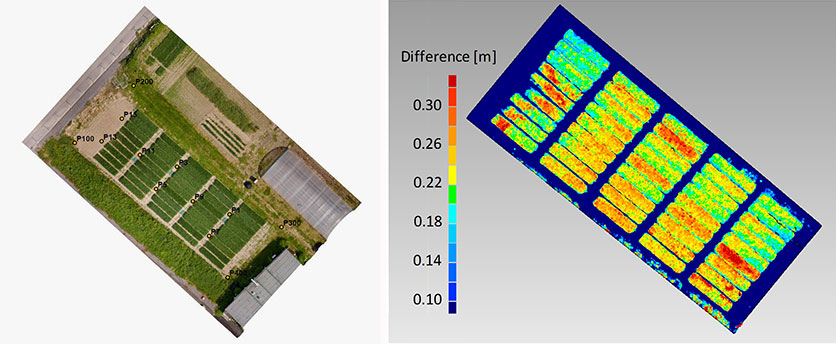
Agriculture. In figure 5, georeferenced images were taken during a flight over a wheat field. The same process was repeated after two weeks. The difference of the respective point clouds, which were determined using the software Photoscan by the company Agisoft, reveals the plant growth at an interval of two weeks. These results show that the determination of plant growth rates, which usually result from time-consuming field work, can be done easily and with high resolution using MAVs. With the use of a direct georeferencing system, this process becomes even more efficient because the deployment of ground control points can be omitted.
Figure 5. Orthophoto of a wheat field (left) and the difference of the vegetation height, determined from the results of two MAV flights at an interval of two weeks (right).
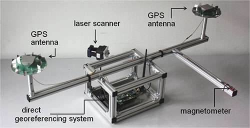
Portable laser scanning system. The small and lightweight design of the direct georeferencing system offers several other opportunities for various applications. One example is the use of the direct georeferencing system in combination with a small, lightweight and low-cost laser scanner.
Terrestrial laser scanning has become an established technology for 3D data acquisition in surveying and mapping because laser scanners provide high-resolution data with high accuracies at high speed. However, for measurement of a complex scene, the laser scanner generally has to be moved to different viewpoints, and all measured scenes have to be registered and georeferenced, a significant increased effort. In contrast, with a directly georeferenced kinematic laser scanning system, complex scenes can be measured with little effort.
Figure 6 shows a portable laser scanning system we developed for kinematic laser scanning. It combines the direct georeferencing system with a low-cost, lightweight 2D time-of-flight laser scanner. Time synchronization and the point cloud calculation are directly realized on this unit.
Figure 6. A directly georeferenced portable laser scanning system for kinematic 3D mapping.
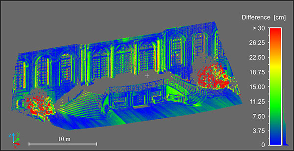
Figure 7 shows differences between a directly georeferenced point cloud, measured by the portable laser scanning system, and a terrestrial laser scanning point cloud, which was indirectly georeferenced using ground control points. Although there are some systematic errors visible, the differences are mostly less than 7.5 cm. The larger differences in the foreground (red) are a result of growing vegetation in the period between both scans. The systematic errors result from the system calibration between the laser scanner and the direct georeferencing system. We are working to improve these calibration methods.
Figure 7. Difference between the results of the directly georeferenced portable laser scanning system and the results of a terrestrial laser scan, which act as reference solution here.
Manufacturers
The MAV is based on a MikroKopter OktoXL assembly kit of HiSystems GmbH. It uses NavXperience 3G+C GPS antennas. The system consists of a dual-frequency NovAtel OEM 615 GPS receiver, a single-frequency u-blox LEA6T receiver, an Analog Devices ADIS 16488 IMU, a Honeywell HMC5883L magnetometer, an XBee Pro 868 radio module, a National Instruments sbRIO 9606 processing unit and a Hokuyo UTM30LXEW 2D time-of-flight laser scanner.
Christian Eling holds an MSc degree in geodesy and is a scientific assistant at the Institute of Geodesy and Geoinformation (IGG) of the University of Bonn.
Lasse Klingbeil received his Ph.D. in experimental physics in 2006. He heads the GNSS and mobile multi-sensor systems group in the IGG. Markus Wieland is a graduade mechanical engineer responsible for the mechanical and electrical design and for the control and readout of various sensor systems at the IGG.
Erik Heinz received his MSc in geodesy and geoinformation from the University of Bonn. He is a Ph.D. student at the IGG. Heiner Kuhlman is a full professor at the IGG. He has worked extensively in engineering surveying, measurement techniques and calibration of geodetic instruments.
VisionMap’s A3 Edge Digital Mapping System was recently used to map wildlife in an African national park. A3 Edge provides an efficient solution for detecting, tracking and estimating wildlife populations, according to maker VisionMap.
The A3 Edge camera surveyed the park from an altitude of 4,000 ft. above ground level (AGL), capturing 3.5 cm resolution imagery at a rate of 225 km2/ hour. A3 Edge uses a “sweep” capture technology that provides quick, high-resolution coverage of vast areas.
Among the animals identified in the images were antelopes, elephants, hippopotamuses and giraffes. The animals’ locations are clearly visible in the aerial images, and the automatic object recognition capability available with VisionMap systems makes it easy to calculate the number of animals in a particular area.
VisionMap’s LightSpeed processing system automatically processes VisionMap images, producing aerial triangulation, orthophoto, digital surface model (DSM), 3D models, and georeferenced vertical and oblique images. The system’s fast turnaround time makes it possible to regularly survey the area, and collect useful information about the animals’ behaviors and trends, VisionMap said.
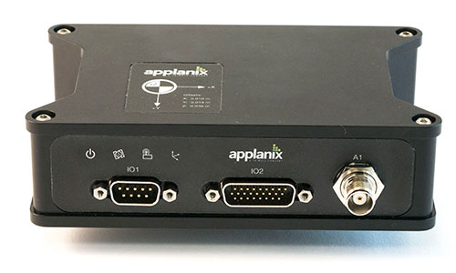
Applanix Corporation has announced the POS AVX 210, the latest addition to its airborne position and orientation portfolio for direct georeferencing of airborne mapping sensors. Using Applanix’ GNSS and inertial technology, the POS AVX 210 enables airborne surveyors to achieve gains in accuracy, efficiency and productivity for low-altitude or small form factor sensors, when compared to GNSS-only point-matching or aerial triangulation techniques.
The announcement was made at the INTERGEO 2015 conference and exhibition in Stuttgart, where Applanix is exhibiting in Hall 8, Booth C8.047.
For photogrammetric applications, the POS AVX 210 delivers highly accurate exterior orientation solutions — reducing the requirement for ground control in assisted aerial triangulation of digital single lens reflex (DSLR) or medium-format photogrammetric imagery. For low-altitude lidar applications, the POS AVX 210 provides the required precision and accuracy of direct georeferencing to enable users to generate point clouds for further refinement in adjustment software.
The POS AVX 210 is fully compatible with, and supported by, POSPac MMS, Applanix’ post-mission software for direct georeferencing of airborne mapping sensors. It is also features a seamless integration with the NanoTrack system from Track’Air, a leading commercial flight management system designed for highly efficient survey flight operations. Aircraft equipped with the POS AVX 210 and NanoTrack will be able to fly missions with reduced sidelap between flightlines, and a greatly reduced requirement for ground control points. These benefits can reduce costs and improve the efficiency of both data collection and the production of finished data sets for end users.
“With POS AVX 210, Applanix has answered a need in the marketplace for a small, compact system that enables efficient data gathering from low-cost yet highly effective sensors. These include DSLR and Medium format cameras, low-altitude lidar systems, and other systems,” said Joe Hutton, director of Inertial Technology and Airborne Products at Applanix.
POS AVX 210 consists of a single rugged enclosure containing a precision GNSS receiver and micro-electro-mechanical-system (MEMS) inertial sensors calibrated with the Applanix SmartCal technology, coupled with on-board data logging capability and interfaces for mapping sensors and flight management systems. POSPac MMS, available as an option with POS AVX 210, is a powerful GNSS-inertial processing software package that includes proprietary advanced capabilities such as the Applanix SmartBase virtual reference station, Applanix InFusion algorithms for increased productivity, and CalQC, a suite of data optimization and quality management tools.
“POS AVX 210 builds on the technological foundation of our established POS AV portfolio for large format sensors, and brings into play the innovations developed for our unmanned solutions. This combination of experience and innovation enables us to deliver a package that strikes the optimal balance between price and performance for this segment,” Hutton said.
POS AVX 210 is expected to be available in the first quarter of 2016 through Applanix’ airborne sales channels.
Avenza Systems Inc., producers of MAPublisher cartographic software for Adobe Illustrator and the PDF Maps mobile app, has released Geographic Imager 5.0 for Adobe Photoshop. This latest release is compatible with Adobe Photoshop Creative Cloud 2015 for both Windows and Mac.
Among the new features, the Georeference tool has been redesigned to provide more flexibility and interactivity when referencing and rectifying images. This release also introduces map package export compatible with the PDF Maps mobile app and the upload of map packages directly to the PDF Maps digital map store.
“We’ve been working diligently on this release of Geographic Imager to allow users to work with their spatial imagery and data in Adobe Photoshop Creative Cloud 2015,” said Ted Florence, president of Avenza. “Geographic Imager is an excellent add-on to Photoshop and proves to be a competitive geospatial image editing platform for many GIS professionals in the industry. We’re looking forward to continuing to develop new tools for the Creative Cloud platform to improve productivity and to streamline workflows.”
Additional Geographic Imager 5.0 Features
Fully compatible with Adobe Photoshop CC 2015
Redesigned Georeference tool: reference with online maps, coordinate system detection, and improved rectification process
New export DEM formats: ArcInfo ASCII Grid and BIL
New online help and help integrated into dialogs
New ability to export a PDF Maps package and upload it directly to the PDF Maps digital map store
New ability to record operations, errors, and messages to event log
New mosaic options including ability to apply blending mode and place mosaic layers above destination layer
Optimized Export to Web Tiles and now includes image interpolation methods and support for OpenStreetMap and TileMill
Enhanced scripting support now includes WMS import
New Preferences interface and options
Various other bug fixes and user experience enhancements
Geographic Imager software for Adobe Photoshop leverages the superior image editing capabilities of the world’s premier raster-based image editing software and transforms it into a powerful geospatial production tool. Work with satellite imagery, aerial photography, orthophotos, and DEMs in GeoTIFF and other major GIS image formats using Adobe Photoshop features such as transparencies, filters, and image adjustments while maintaining georeferencing and support for hundreds of coordinate systems and projections.
Geographic Imager 5.0 is immediately available and free of charge to all current Geographic Imager Maintenance Program members and at US$319 for non-maintenance upgrades. New fixed licenses start at US$699. Geographic Imager Basic licenses start at US$99. Academic, floating and volume license pricing are also available. Geographic Imager 5.0 is compatible with Adobe Photoshop CS6, CC 2014 and CC 2015. Adobe Photoshop CS5 and CC are supported but deprecated in this release.
Avyon, a sUAS (Small Unmanned Aircraft Systems) integrator and distributor, is using the Applanix APX UAV for its md4 fleet, to provide users with cost-effective direct georeferencing technology.
The integration of the Applanix APX-15 UAV on the md4-1000 and md4-3000 microdrones will offer solutions for unmanned aircraft while complying with weight and size restrictions for payloads. The APX-15 works seamlessly with all other airborne sensors such as digital cameras, LIDAR and other sensors, Avy0n said.
The APX-15 on the md4-1000 microdrone is on display at booth 1803 at the AUVSI Unmanned Systems 2015 show, being held May 4-7 in Atlanta, Ga.
“The integration of the APX-15 with md4-1000 and md4-3000 will provide users with a precision mapping capability, minimizing or eliminating the requirement for ground control points and making mapping missions more efficient,” said Mike Hogan, Avyon’s business development manager.
The APX-15 UAV on the md4 fleet will improve aerial mapping by eliminating GCPs (ground control points) for triangulation, as well as reduce the amount of overlap in the surveying process. This will increase efficiency and effectiveness for area flown per mission and the post-mission data processing, Avyon said.
“We recognize the need to provide the growing UAS mapping market with the same highly efficient solutions that we pioneered for airborne mapping over 15 years ago,” said Joe Hutton, director of Inertial Technology and Airborne Products at Applanix Corporation (xyHt pg. 14). “We are now offering a cost-effective solution that meets the size, weight, power and cost requirements of small UAS, and maintains the Applanix pedigree for quality and performance. We are pleased Avyon has partnered with us. The md4-1000 DMS-UAV is a powerful new solution.”
The unmanned drone RQ-4 Global Hawk in flight in 2007 (Image credit: U.S. Air Force photo by Bobbi Zapka)
By Art Kalinski, GISP
For more than a decade, the military has been struggling with cataloging and retrieving its huge libraries of full motion video (FMV). The video, captured by both manned and unmanned aircraft, rapidly reached unmanageable levels. If you have ever tried to organize vacation photos after returning home from a long trip, you know that it’s easy to lose track of where each photo was taken. Date/time stamps help, but the effort is still difficult if your vacation took you to numerous locations.
The manned U.S. Air Force Beech King Air 350 and 350ER MC-12W Project Liberty Aircraft are designed for intelligence, surveillance and reconnaissance (ISR).
Now imagine trying to retrieve several critical minutes out of thousands of hours of video of barren land or repetitive-looking villages, and you get a sense of the magnitude of the problem. Without some way to catalog the video, critical details can be lost, because finding the right video clip becomes impossible in a reasonable period of time. Everyone agreed that the solution to the problem is to index the video clips by date/time and location, preferably with an exact georeferenced footprint. This is now possible with tools from Esri, Hexagon Geospatial and others.
Several years ago, at the USGIF GEOINT Tech Days, Sarnoff (SRI) demonstrated a system that pinned aerial video to its geographic footprint and maintained that registration despite the movement of the aircraft. It was an achievement that impressed everyone in the audience. I changed jobs soon after that conference and lost track of developments in the FMV field. At the February Esri Federal Users Conference, I was thrilled to see Jack Dangermond briefly demonstrate the same kind of FMV georeferencing capability in ArcGIS 10.2 during his opening plenary session. I learned that Esri developed the capability in 2013, and later learned that Intergraph (Hexagon Geospatial) also developed a similar capability in 2010.
MISB: The Critical Improvement
The key technical development that made this possible was NGA’s creation of “Motion Imagery Standards” and the Motion Imagery Standards Board (MISB). The MISB developed standards for a consistent way to capture and record telemetry data during the video capture as metadata that becomes part of the video stream. This “Open Standard” metadata includes information such as the accurate xyz location of the aircraft, attitude, tilt, camera angle, and camera characteristics. This information travels with the individual video frames and permits the GIS/viewing software to perform the georeferencing.
This process is very similar to the oblique imagery capture system used for years by Pictometry, which at 20 FPS was technically FMV. MISB like Pictometry requires accurate GPS and IMU data to continuously capture and record the metadata. The MISB also gets involved with video compression standards such as the newer H.264 used on Blu-Ray discs and streaming video. H.264 has, for the most part, replaced MPEG2 and older MPEG4 as the video compression standard of choice. Much of the video captured by low-end small UAVs is just a simple video stream with no MISB telemetry data. However, I’m sure that lower prices, increased capability and smaller size of sensors will fix that with time. Sorry, no one has yet figured a way to “hack in” the metadata for legacy video captured without the MISB telemetry data. The one exception is those videos that contain usable telemetry data that was burned into the video and can be read with OCR. It might be possible to insert that information as MISB-compliant data.
The ArcGIS Full Motion Video Add-In
The ArcGIS Full Motion Video 1.2 Add-In (for ArcGIS 10.1, 10.2 and 10.3) is a free tool for ArcGIS users. It permits users to play georeferenced live or previously recorded video files in the map view. The screen capture below shows several features of this tool and is from an online video.
The re-sizeable smaller window displays the video as it runs. The map view shows a changing footprint (green trapezoid) of the video as the aircraft flies over the site. The short green line shows the flight path of the aircraft. Demonstrating the interconnectivity of the two data sets, the user in the demo video drew a light blue polygon on the map view. Note that the Esri Intersect function re-projects and displays the same polygon correctly in the video view.
Frames from the video can be extracted as single georeferenced images or groups of images and stored as a mosaic dataset. Playback of time-stamped video data can be synchronized with other time-enabled data and played together on the map. Features can be digitized directly on the video player and will appear on the map and vice versa.
The extension supports playback and management of multiple simultaneous video feeds. The Add-In also allows you to record the sensor, frame center, and footprint data in a geodatabase so the Bookmark Manager can perform searches for bookmarked video scenes. For more information regarding the Esri FMV tool, visit this ArcGiS site.
Hexagon Geospatial GeoMedia Motion Video Analyst Professional
Another robust FMV system that takes advantage of MISB telemetry is GeoMedia Motion Video Analyst Professional (MVA) from Hexagon Geospatial. The Hexagon Geospatial system includes tools to catalog videos as geospatial features with attributes extracted from the metadata, and has some elegant graphic selection tools that help an operator search and retrieve needed video clips.
In the screen capture below, you can see the map view with the geo-registered color video overlaid on the black-and-white ortho base image. As the video plays, the georeferenced video footprint continuously moves to the correct location as the tracking graphics in red show the position of the aircraft. The transparency of the video can be adjusted so an operator can compare features between the base image and the video and digitize directly in the map window.
MVA also includes a full set of tools for placing clipmarks as geospatial features with attributes and linked to the cataloged video, extracting snapshots and videos clips, on-the-fly enhancements, stabilization, registration and more. The system also facilitates rapid report generation so as an operator searches and plays appropriate video clips, the same operator or a partner can rapidly generate reports as documents or PowerPoint presentations in minutes. Another feature of the system is a “de-hazing” tool that removes a surprising amount of haze or smoke.
See a very good video overview of GeoMedia Motion Video Analyst Professional on this Hexagon Geospatial page. Like the Esri video, both are far better at explaining the capabilities than I can in this short column.
Other defense contractors are taking advantage of the MISB metadata, so check with your provider. Although these systems found their first home with military analysts, the Esri and Hexagon Geospatial reps indicated that many other users are finding the capability valuable in their work. Emergency operations centers come to mind first, but more mundane uses include rail and utility property management, the news media and video used in court proceedings. So, if you shoot lots of aerial video and need to catalog and retrieve video clips quickly, consider using MISB in your capture process.