Taoglas will showcase its latest antenna technologies at the 2026 European Conference on Antennas and Propagation (EuCAP) in Dublin, Ireland, taking place April 19-24, in the Dublin convention center. Taoglas will display at Stand 52.
At this year’s exhibition and conference, Taoglas will underline the increasing complexity of antenna integration in electronic systems, where performance depends on interactions between the antenna, PCB, enclosure and multi‑radio environment.
The company also will host a “GNSS Evolution Masterclass: Bridging Theory and Field Performance” on April 21, 15:50-17:30. The session will cover the evolution from single‑band to multi‑band GNSS and provide practical guidance on antenna characteristics, performance metrics, correction services and evaluation methods for real‑world positioning performance.
At its booth, Taoglas will highlight its AI-driven Antenna Product Recommendation Engine, designed to help users identify antenna options based on needs. It complements Taoglas’ existing design and configuration tools, including the Antenna Integrator for PCB placement, which adds new features and antenna models frequently, enabling a seamless path from initial selection through to integration.
In the technical conference programme, Taoglas will also present new antenna design work, including a poster on innovations in tri‑band Wi‑Fi antenna integration and a paper on compact antennas for LPWA and IoT devices.
“EuCAP is a unique opportunity to connect cutting‑edge research with real‑world engineering challenges,” said Dermot O’Shea, co‑founder and CEO of Taoglas. “With Taoglas’ roots in Ireland, it is especially rewarding to highlight local RF and antenna expertise while engaging with the global engineering community.”
Taoglas is supporting EuCAP 2026 as a gold sponsor. Visitors can meet the Taoglas team at the event or visit www.taoglas.com for more information.
Quectel Wireless Solutions has introduced four new GNSS antennas. The new antennas include:
The YFGD000AA high-precision, low-profile antenna which covers all GNSS bands
The YFGD000BA, optimized for triple-band solutions in GNSS L1, L2 and L5 bands
The YFGN000H1AC high-precision, lightweight antenna that again covers all GNSS bands
The YEGT010W1AM, designed for general-purpose reception in non-precision applications.
Quectel’s triple-band and all-band antennas are built to maximize performance with the latest generation of RTK GNSS modules. These include the LC29H dual-band module, designed for cost-sensitive yet precision-critical applications; the LG290P industrial-grade module, delivering centimetre-level accuracy with RTK fix times under five seconds; and the flagship LG580P, which adds L6 support and dual-antenna heading, making it suitable for ADAS, robotics and autonomous systems.
Complementing the hardware, Quectel’s global RTK correction service leverages a network of more than 21,000 base stations to provide consistent centimeter-level accuracy worldwide, ensuring seamless coverage across Asia, Europe and North America, and enabling scalability for industries such as agriculture, logistics and automotive.
The YFGD000AA is a high-performance multi-band active GNSS antenna designed for professional applications requiring ultra-precise positioning across L1, L2, L5, L6 and L-Band frequencies (1164–1300 MHz and 1525–1606 MHz). With dimensions of 78.6mm x 75.6mm x 16.2mm and a screw mounting, the antenna is suitable for vehicular or fixed installations and operates in the -40 °C to +85 °C temperature range. Combining exceptional signal sensitivity with rugged durability, this antenna is engineered for mission-critical deployments in autonomous systems, geodetic surveying and high-accuracy navigation. It is RoHS, REACH and POPS compliant.
The YFGD000BA offers similar capabilities to the YFGD000AA but has been developed to support professional applications with ultra-precise positioning needs across L1, L2 and L5 bands (1164–1238 MHz and 1559–1606 MHz). It shares dimensions, operating temperature range and mounting options with the YFGD000AA and is also RoHS, REACH and POPs compliant. Both the YFGD000AA and YFGD000BA can support high-precision RTK despite their compact size.
The YFGN000H1AC is a high-precision antenna with a higher profile than the YFGD000AA and YFGD000BA but with greater performance and lighter weight of 62g. The antenna covers all GNSS bands, ensuring worldwide compatibility. It delivers 35 ±4 dB gain with a low noise figure of ≤4 dB, making it suitable for weak-signal environments like urban canyons or dense foliage. With a diameter of 122mm and height of 22.5mm, the antenna features a screw mounting so it can be attached to vehicles or fixed installations. It operates in –40 °C to +85 °C temperature range and is RoHS and REACH compliant. Should customers require it, Quectel can supply enclosures to convert the antenna from an internal to external set up.
Finally, the YEGT010W1AM is a GNSS rubber external antenna with a diameter of 10.22 mm and height of 69.5 mm. This ultra-wide-band GNSS antenna provides broad coverage from 1559–1606 MHz and is terminated with an SMA male connector. With omnidirectional capability and linear polarization, YEGT010W1AM is designed for general-purpose reception in non-precision applications, especially where signal direction varies.
The terminal mount design, with a compact, rugged form factor makes it easy to install on gateways, routers or tracking devices in protected environments. Operating in the –40 °C to +85 °C temperature range, the antenna weighs 8.9g and is RoHS compliant. In addition, the antenna’s universal joint design allows customers to easily adjust the polarization direction, helping to mitigate the angle sensitivity commonly associated with linearly polarized antennas in real-world applications, therefore enhancing overall signal stability.
In addition to the antennas, Quectel provides comprehensive antenna design support services such as simulation, testing and manufacturing for custom antenna solutions to meet developers’ and designers’ specific application needs.
IT’S ALL PHYSICS. How things work, that is. Well, maybe a little chemistry too in some cases. I might be a little biased in my opinion given that I’m an applied physicist by training. Radio? Satellite navigation? Yes, the principles of their operation are all governed by physics. Many physicists of my generation started out as radio tinkerers. I’ve recounted in this column before that I built my first radio (from a kit) when I was 14 (not counting the crystal radio that my father helped me to put together when I was 8 or 9). I built a few more during high school, got into radio astronomy as an undergraduate and did a Ph.D. in the application of very long baseline (radio) interferometry to geodesy.
The great American physicist Richard Feynman was also a radio tinkerer in his youth. He recounts in one of his autobiographical books how he used to fix radios. Since he would approach the task of repairing each non-functioning set by first contemplating why it wasn’t working, he got the reputation of fixing radios by thinking!
One of Feynman’s special abilities was in explaining how things worked. In fact, he has been called “The Great Explainer.” He authored what is arguably the best physics textbooks ever produced: The Feynman Lectures on Physics. The three-volume set, developed from his Caltech lectures to undergraduates between 1961 and 1964, covers mechanics, radiation, electromagnetism, matter and quantum mechanics. Many students and practicing physicists have learned or relearned aspects of physics from the famous “red books.” Many more will now thank Caltech, which recently put the Lectures online for anyone to read.
In the February 2016 column, we learned about the development of a microprocessor-controlled multi-element GNSS antenna array for interference rejection. While there are many textbooks that describe how multi-element antennas work, Feynman explains their operation in his Lectures from first principles–from the principles of physics. The phenomenon governing the behavior of antennas with multiple elements is called interference.
If we combine two electromagnetic waves, they will interfere with each other with a result that depends on the relative phase (or phase difference) of the waves. The waves might reinforce each other leading to a larger net amplitude, called constructive interference, or partially or fully null each other out, called destructive interference. When we apply this concept to the signals transmitted by a pair of antennas making up an array in a horizontal plane, we find that the array has directionality. That is, if we space the antennas by one-half wavelength of the signal to be transmitted and feed the antennas in phase (zero phase difference), we will transmit a strong signal in the directions perpendicular to the baseline connecting the antennas (say east-west) and no signal in the orthogonal directions (north-south). If we use this antenna pair for receiving, we will have a null in the reception pattern to the north and to the south and will be insensitive to signals arriving from those directions. And as Feynman describes in his lectures, by adding more antennas to the array and “some cleverness in spacing and phasing our antennas,” we can have a fairly narrow pattern null in a chosen direction. In the case of a GNSS antenna array, that direction might be that of a jamming signal and so we can null out the jammer and maintain a positioning capability.
There is more to it in developing a practical microprocessor-controlled GNSS antenna array, but it starts with the physics.
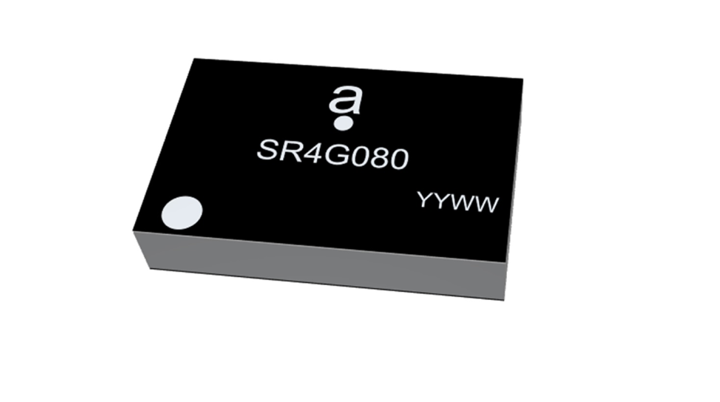
Antenova Ltd. is adding a new offering to its range of miniature surface-mount-designed (SMD) antennas and modules for GNSS applications. The new antenna, Agosti (part number SR4G080), measures 9.0 x 5.8 x 1.7 mm and operates with exceptional efficiency in a reduced space on a corner of a printed circuit board (PCB).
The key advantage of the Agosti antenna is its small ground-plane requirement. Most SMD antennas use the surface of the PCB around the antenna as a ground plane from which to radiate the signal — the ground-plane requirement, not the physical dimensions of the antenna, define the space it needs.
Antenova’s radiated measurement results show Agosti operating well on small ground planes of 40 x 20 mm, 70 x 25 mm and 80 x 30 mm, making it a suitable choice for small form-factor designs, such as small wearable devices, trackers and on-board diagnostics (OBDs).
Agosti is designed to integrate and co-exist with other antennas within the same device. OBDs and trackers often use 4G/LTE with A-GPS for fallback. The Agosti antenna has been tested with Antenova’s Pharoah antenna (part number SR4L073), which also has a very small ground-plane requirement. The two antennas have excellent isolation and can operate in close proximity to each other in a very small device without the 4G signal interfering with sensitive GNSS signals.
“Small SMD antennas such as Agosti are an exciting alternative to the common delicate ceramic patch antennas used in GNSS designs,” said Michael Castle, product marketing manager, Antenova. “This is not just because the SMD antennas are significantly smaller. It is also because they provide omni-directional performance.
“Patch antennas are typically 12 mm or 14 mm square, are heavier than SMD antennas, and need a much larger ground plane and keep-out area,” Castle said. “They also have to be placed in the center of a circuit board and only work well when they point at the sky. Antenova’s new generation of SMD antennas overcome all of these limitations and perform well regardless of position and orientation of the device.”
Tesla has applied to patent a new multi-band GNSS antenna with increased precision for self-driving and navigation in its autos, reports electrek. The antenna would be positioned inside the rear-mirror enclosure, and the system would also provide a heating element.
While increasing precision, it is also designed to reduce power demand, noise and cost.
The automaker describes the new device in the abstract of the new patent application:
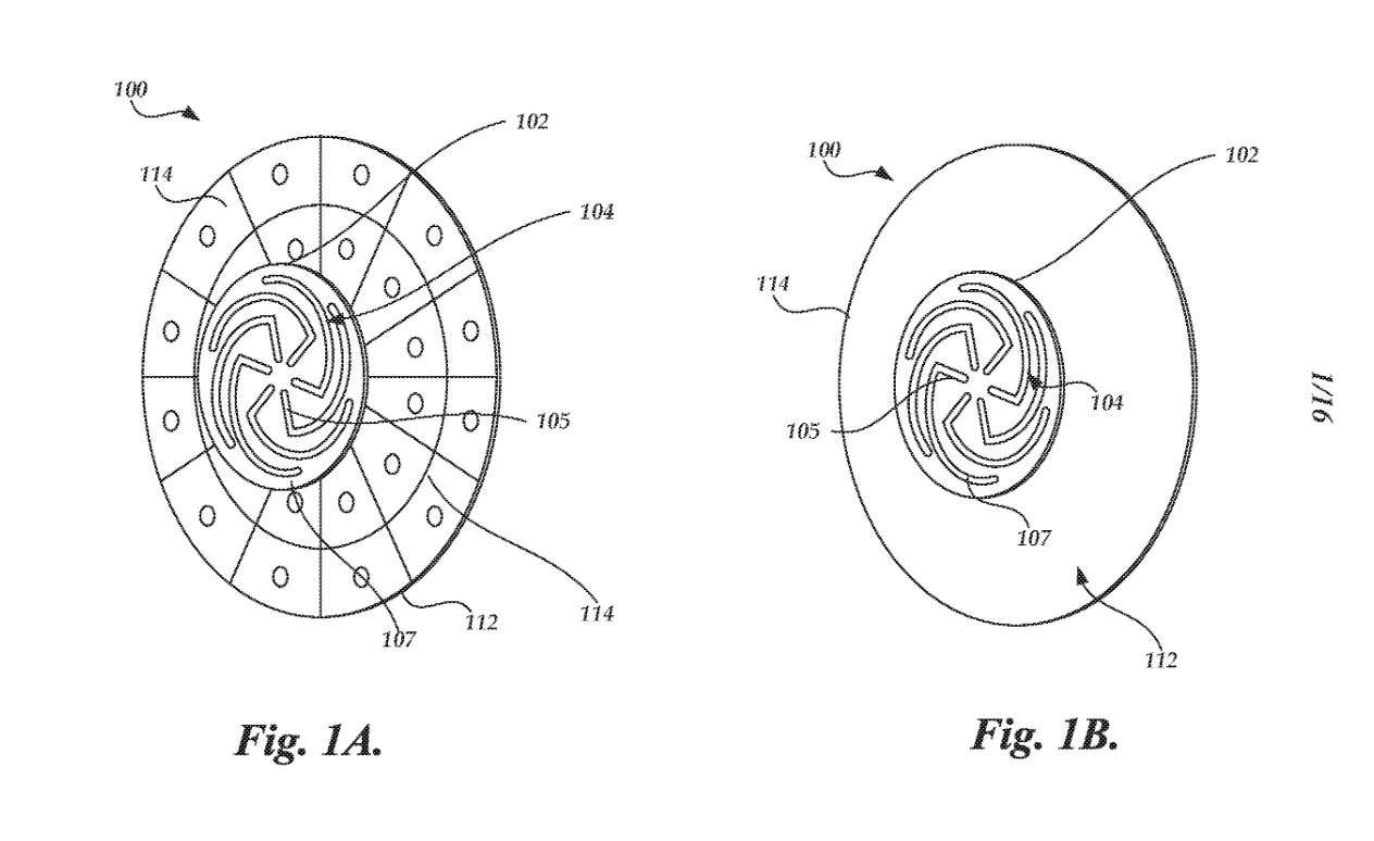
A multi-band antenna system is provided. The antenna system can be placed under and embedded within a glass exterior surface of a vehicle. Such an antenna system can include a capacitively coupled metallic element on or adjacent to the glass exterior surface, which can serve as both a parasitic element to enhance gain and as a heating element to melt snow and/or ice accumulation over the glass area that covers the antenna. In certain applications, the antenna’s structure itself can be used as a heater to improve performance in adverse weather conditions while the heating elements are positioned away from the thermally sensitive electronics. The antenna system with integrated heating can include a spiral antenna.
A diagram of the antenna provided with the patent application. (U.S. Patent Office)
Antenna manufacturer Harxon has launched a new company website, which features eye-catching animations and dynamic illustrations.
“We’ve optimized the website in both the layout and the content,” the company stated in a news release. “You’ll find more detailed product pages, seven major industry applications, and more information about Harxon Corporation.”
New additions include Antenna Customization and Antenna Selection pages, designed to help customers determine which products meet their project needs.
Harxon’s latest products include the survey GNSS antenna HX-CSX633A, the ruggedized HX-CVX606A and the X-Survey OEM antenna HX-CSX179A.
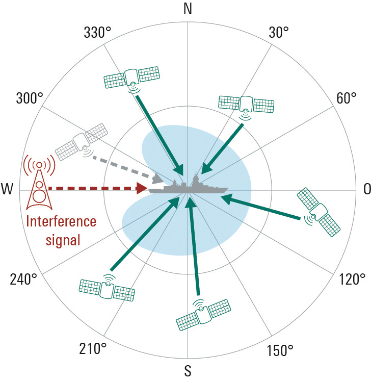
Interference-free GNSS signals are essential for more than just military vehicles and aircraft. Anti-jam systems usually suppress signals from interference sources by means of spatial filtering.
These solutions can likewise be used to protect satellite navigation signals for autonomous driving and flying against interference signals. To allow GNSS receivers to detect interference sources and suppress transmitted interference signals, they must be designed as multichannel systems.
This way the direction of the interference signal can be determined using phase-coherent signal processing of signals from multiple antennas, and the interference can be suppressed. Rohde & Schwarz offers a solution for the verification of interference immunity and interference suppression.
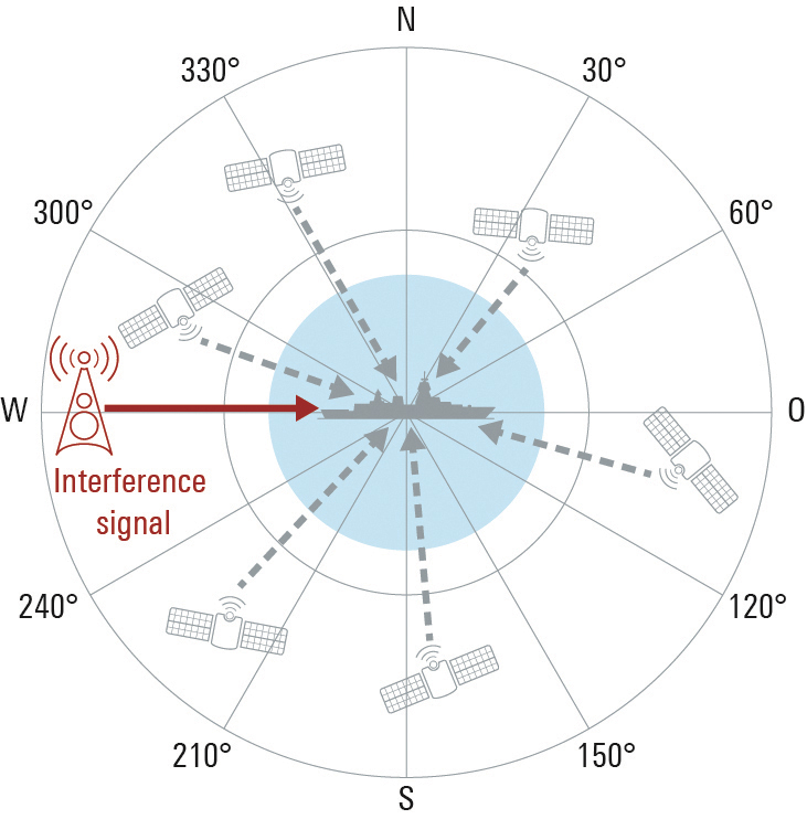
FIGURE 1a. The GNSS antenna in the example on the left has only one element, so its characteristic cannot be modified. A sufficiently strong interference signal can prevent the receiver from processing the GNSS signals, making satellite-based navigation impossible.
FIGURE 1b. In contrast to the individual antenna, the characteristic of the antenna array can be modified by combining and weighting the received signals. The interference signal is suppressed at its angle of arrival, and the GNSS signals can be received. A disadvantage is that GNSS signals from the same direction as the interference signal are also suppressed.
Multi-channel receivers can simultaneously process signals from multiple distributed antennas or from an antenna array. This is useful for determining the direction of incoming signals by means of signal analysis, and for adjusting the antenna pattern so that undesired signals are suppressed. For GNSS-based position determination, this means that signals from global navigation satellite systems (GNSS) can be strengthened and jamming or spoofing signals originating from the ground or the air can be suppressed. Up to now this technology has primarily been used for military applications, but in the future it can also make an important contribution to robust navigation for autonomous driving or flying. Typical interference sources in this regard are harmonics of transmitters in the vicinity, tactical air navigation (TACAN) signals, DME air navigation signals for civil aviation, and LTE signals. Another factor is the growing popularity of so-called personal privacy devices (PPD), which are GNSS jammers that radiate narrowband or broadband signals to disrupt GNSS localization. A new solution from Rohde & Schwarz enables comprehensive testing of the resistance of GNSS receivers to interference signals, if necessary in a realistic hardware-in-the-loop (HIL) environment.
Multi-Channel GNSS Receivers for Interference Suppression
GNSS receivers often use controlled reception pattern antennas (CRPA) to suppress undesired signals. These antennas consist of an antenna array and a signal processing unit. The connected antennas are generally arranged in a strict geometric pattern to achieve full coverage of all possible signal directions. The overall receive characteristic of the antenna array can be altered by suitable weighting of the signals from the individual antennas in the signal processing unit (Fig. 1). This way, interference signals can be specifically blanked out (nulling) or the required GNSS signals can be amplified at their angle of arrival (beamforming). A combination of these two methods is also possible. The antenna arrays typically consist of four to seven elements. The number of interference signals that can be simultaneously suppressed increases with the number of elements.
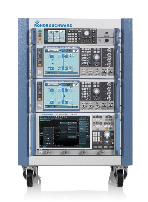
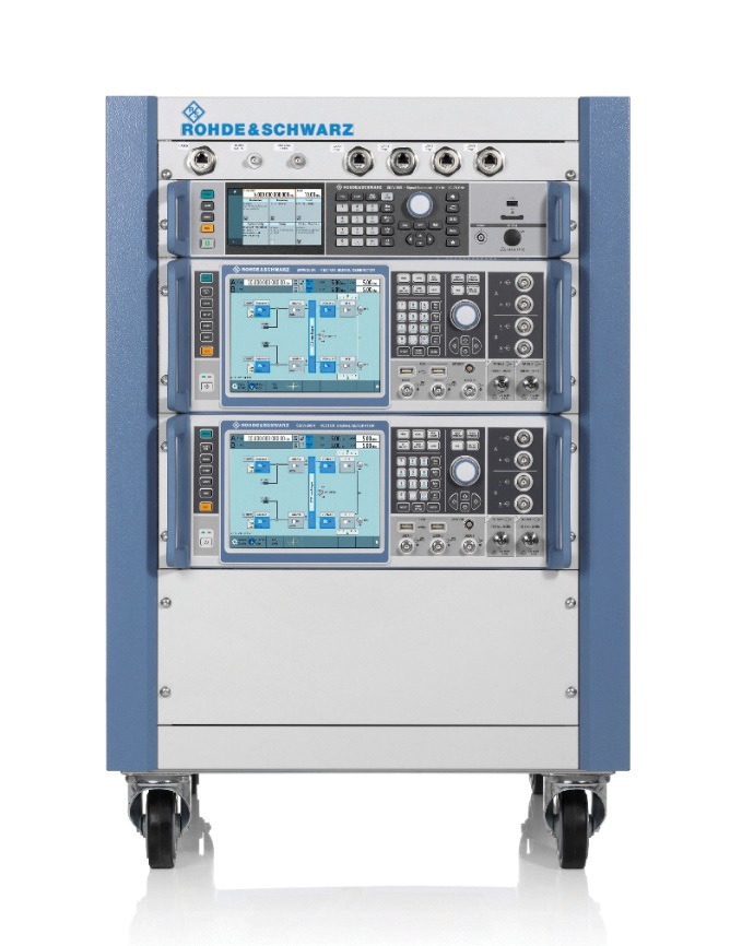
FIGURE 2a. A four-channel GNSS test system consisting of two R&S SMW200A vector signal generators and an R&S SMA100B analog signal generator for the LO signal (left). The vector network analyzer is used to calibrate the overall system at a user-selectable reference plane in terms of amplitude, phase and propagation time.
FIGURE 2b. A four-channel GNSS test system consisting of two R&S SMW200A vector signal generators and an R&S SMA100B analog signal generator for the LO signal (left). The vector network analyzer is used to calibrate the overall system at a user-selectable reference plane in terms of amplitude, phase and propagation time.
Test System Requirements
Rohde & Schwarz offers a test system for GNSS receivers that use CRPAs. First, it acts as a multichannel GNSS simulator that considers all aspects of a satellite navigation system. It must be able to generate the signals of all standard satellite navigation systems in all GNSS frequency bands, with attention to correct satellite orbits, signal propagation characteristics and realistic modeling of the dynamically changing receive environment. Configuration of the antenna array in terms of geometry and the receive characteristics of the individual antennas also must be included.
Simulating the Interference Signals
Second, the system can simultaneously generate jamming or spoofing signals in order to test the interference suppression functions of the device under test (DUT). A second, identical test system is necessary for freely definable configuration of interference sources with very high transmit power. Here the R&S Pulse Sequencer software assists in the definition of complex interference scenarios. The scenarios cover requirements such as long simulation times, moving interference sources and GNSS receivers, user-defined antenna patterns and antenna scans. In addition, the software calculates the correct amplitude, phase angle and propagation time of the signals as a function of signal frequency, antenna arrangement, and the positions of transmitters and receivers in three-dimensional space for each individual antenna element. Signal generation is handled by the R&S SMW200A high-end vector signal generator.
For the tests, the required GNSS signal as well as the unwanted interference signals must be generated for each antenna input of the GNSS receiver. In order to test a CRPA receiver with four antenna inputs, this means that four signal sources are needed to generate the GNSS signals and an additional four signal sources are needed to generate the interference signals. Fig. 2 shows a pair of test systems that can be used to generate coupled GNSS signals and interference signals for a four-channel CRPA receiver.
Calibration Against the DUT
In order to correctly simulate the directions of the satellite signals and the interference signals, the test systems must be calibrated at the RF interface to the DUT with regard to amplitude, phase and propagation time. This means that the amplitude, phase and propagation time differences between the individual RF paths, resulting for example from cables or RF components, must be compensated. The vector signal generators of each system are phase coherently linked using suitable synchronization. A high-end R&S SMA100B analog signal generator in each system provides the shared LO signal.
Using the R&S RF Ports alignment software, the complete system can be calibrated at any desired reference plane with regard to amplitude, phase and propagation time, so that the properties of the test system do not corrupt the simulated signal differences between the individual antennas. The required measurements are performed with a vector network analyzer.
It is not necessary to calibrate the two test systems relative to each other. For the simulation of realistic scenarios, it is sufficient to run the GNSS and interference source simulations at the same time, since in the real world there is usually no correlation between GNSS satellites and interference sources.
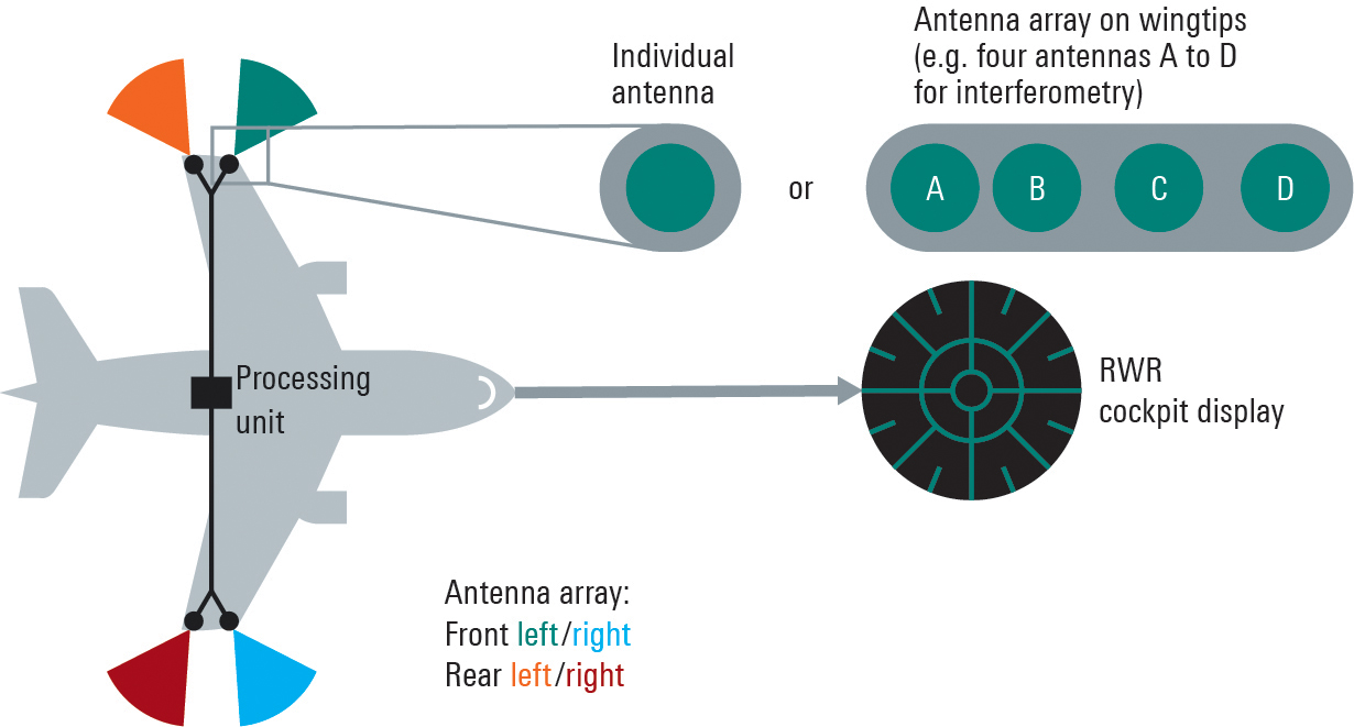
FIGURE 3. Aircraft with a multichannel radar warning system consisting of multiple receive channels, a central processing unit and a display.
Integration in an HIL Environment
The GNSS test system also can be embedded in a hardware-in-the-loop (HIL) environment. In this case a computer streams the motion profile of the GNSS receiver under test, with position, speed, acceleration and vehicle attitude, to the test system at a high data rate. The test system then generates the corresponding satellite navigation signal in real time. This requires very high update rates and low latencies.
Summary
Multichannel GNSS CRPA receivers considerably improve the navigation of ground vehicles and aircraft of all kinds. With the new Rohde & Schwarz test system, realistic multi-channel test signals can be generated for both GNSS simulation and interference simulation. For tests in an HIL environment, motion data also can be streamed to the GNSS test system.
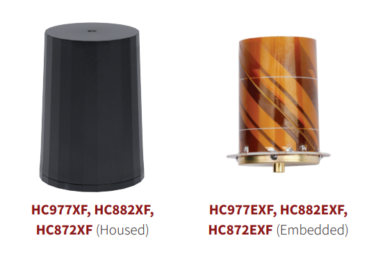
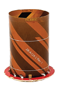
Tallysman Wireless has added eXtended Filtering (XF) to the housed and embedded lightweight HC977XF (triple-band + L-band), HC882XF (dual band + L-band) and HC872XF (dual-band (GPS and GLONASS) + L-band) precision helical GNSS antennas.
Tallysman has designed the XF feature to mitigate interference from all near-band signals and ensure that the antenna provides the purest GNSS signals.
The radio-frequency spectrum has become congested worldwide as many new LTE bands have been activated, and their signals or harmonic frequencies can affect GNSS antennas and receivers. In North America, the planned Ligado service, which will broadcast in the frequency range of 1526–1536 MHz, can affect GNSS antennas that receive space-based L-band correction service signals (1539–1559 MHz). New LTE signals in Europe (band 32, 1452–1496 MHz) and Japan (bands 11 and 21, 1476–1511 MHz) have also affected GNSS signals.
Tallysman’s housed helical antennas weigh ~42 g and are enclosed in a robust military-grade IP67 plastic enclosure. The antenna base has an integrated SMA connector, a waterproofing O-ring, and three screw holes to enable secure attachment. Tallysman’s embedded helical antennas weigh ~8 g and are easily mounted with an optional embedded helical mounting ring, which traps the outer edge of the antenna circuit board to the host circuit board or any flat surface.
An MCX connector is installed in the base of the antenna.
Tallysman helical antennas are suitable for a variety of applications, including lightweight unmanned autonomous vehicle navigation (land, sea and air), land survey devices, automotive positioning, timing and other precise-positioning applications.
The HC885EXF embedded helical antenna. (Photo: Tallysman)
Tallysman Wireless has added the housed HC885XF and embedded HC885EXF dual-band eXtended Filtering (XF) antennas to its line of helical antennas.
The antennas receive GPS/QZSS L1/L5, GLONASS G1/G3, Galileo E1/ E5a/b, BeiDou B1/B2/B2a and L-band corrections services.
Historically, dual-frequency antennas and receivers commonly supported GPS L1 and L2 and GLONASS G1 and G2. In recent years, GPS, GLONASS, Galileo, BeiDou and NavIC have added GNSS signals in the L5 frequency band (1160-1217 MHz).
As a result, the new dual-frequency GNSS standard has become L1 and L5.
Tallysman’s new HC885XF antenna has been tuned to provide optimal support for the entire L1/G1/E1/B1/L-band correction and L5/G3/E5/B2 bands.
The radio frequency spectrum has become congested worldwide as many new LTE bands have been activated, and their signals or harmonic frequencies can affect GNSS antennas and receivers. In North America, the planned Ligado service, which will broadcast in the frequency range of 1526 to 1536 MHz, can affect GNSS antennas that receive space-based L-band correction service signals (1539-1559 MHz). New LTE signals in Europe [Band 32 (1452-1496 MHz)] and Japan [Bands 11 and 21 (1476-1511 MHz)] have also affected GNSS signals. Tallyman’s XF models mitigate the effects of these new signals.
The Tallysman HC885XF housed helical antenna weighs ~42 g and is enclosed in a robust, military-grade IP67 plastic enclosure. The antenna base has an integrated SMA connector, a water-proofing O-ring, and three screw holes to enable secure attachment.
Tallysman’s embedded HC885EXF helical antenna weighs ~8 g. It is easily mounted with an optional embedded helical mounting ring, which traps the outer edge of the antenna circuit board to the host circuit board or any flat surface. An MCX connector is installed in the base of the antenna.
Tallysman HC885EXF and HC885XF antennas are suitable for a variety of applications, including lightweight unmanned autonomous vehicle navigation (land, sea, and air), land survey devices, automotive positioning, timing and other precise-positioning applications.
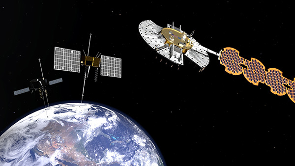
More than 100 experiments will be conducted with the Navigation Technology Satellite-3 (NTS-3), set to launch next year, according to a U.S. Air Force official and reported by FedScoop.
“We’re really excited to push the state of the art with more than 100 experiments on this little [NTS-3] spacecraft and we’re looking at ways that we can solve warfighters’ problems in the contested environment,” Maj. Gen. Heather Pringle, commander of AFRL, told reporters April 6 at the 37th Space Symposium in Colorado Springs.
Maj. Gen. Heather Pringle
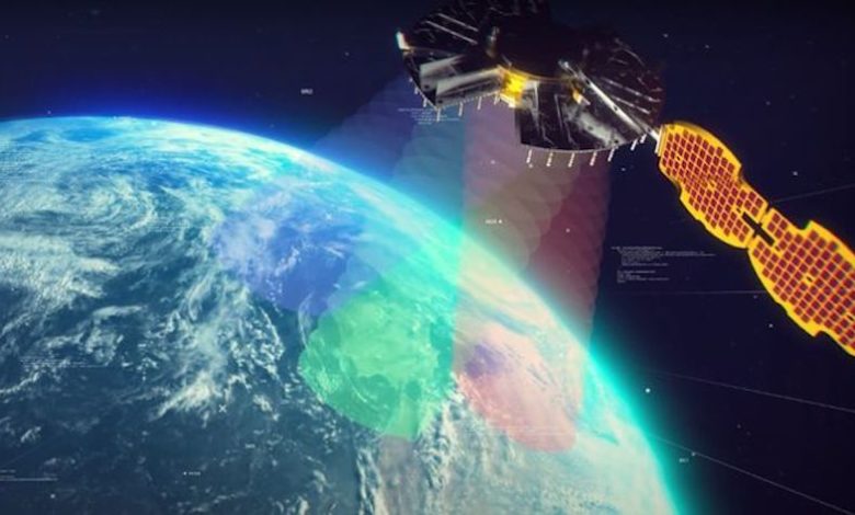
Set to launch in 2023, NTS-3 is designed to push the boundary of today’s position, navigation and timing (PNT) technology to pave the way for a more flexible, robust, and resilient architecture for satellite navigation technology.
NTS-3 is a product of the Air Force Research Laboratory (AFRL) and industry, designed to test advanced techniques and technologies to detect and mitigate interference to PNT capabilities and increase system resiliency for military, civil, and commercial users.
Unlike the GPS medium-Earth-orbit satellites, NTS-3 will operate for one year in geosynchronous Earth orbit. Ultimately, NTS-3 will identify key aspects for new GPS receivers that incorporate multiple signals and readily adapt to warfighter needs.
The NTS-3 experiments will also involve ground equipment and terminals such as command and control stations and software-defined radios. Specific improvements to the ground segment will enable experimentation with automated “lights-out” operations, control station failover, and near-real time environment sensing and generation of error correction and tailored waveforms. Onboard systems will monitor clock accuracy and orbit parameters to mitigate errors and notify the user.
NTS-3 will test a new digital signal generator that can be reprogrammed on-orbit, enabling it to broadcast new signals, improve performance by avoiding and defeating interference, and adding signatures to counter spoofing.
AFRL also will explore antenna configurations to provide Earth coverage and steerable regional beams in multiple frequencies and signal codes. The NTS-3 satellite will be equipped with 110 antennas to help counter attempted GPS jamming.
Ultimately, NTS-3 is expected to provide users with enhanced signal stability, availability, integrity and accuracy.
L3Harris plans to deliver NTS-3 later this year. The company is assembling the satellite at its Palm Bay facility near Cape Canaveral, Florida. The plant was expanded in 2021 to accommodate the NTS-3 program.
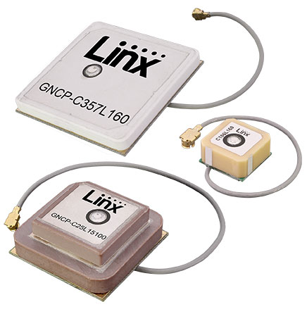
Linx Technologies has introduced seven GNSS active ceramic-patch antennas. These antennas support global GNSS applications including GPS, Galileo, GLONASS, Beidou, NavIC and QZSS systems in the L1/E1/B1, L2/E5/B2B, and L5/E5/B2A bands.
Each antenna integrates a high-gain low-noise amplifier (LNA) and right-hand circular polarization (RHCP) to provide a high-performance solution for GNSS signal reception. Each active GNSS antenna has either a 60-mm or 100-mm coaxial cable terminated in a MHF1/U.FL-type plug (female socket) connector.
“Linx Technologies continues to expand our popular GNSS antenna portfolio by adding more L1 options to serve our customers’ varied size and performance requirements,” said Linx CEO, Tolga Latif. “Our new active ceramic patch GNSS antennas also meet the need for multi-band L1/L2, L1/L5, and L1/L2/L5 GNSS offerings.”
The new active GNSS antennas are available now via Linx Technologies’ distributor and manufacturer representative networks. For larger quotes, contact Linx Technologies at [email protected].
Taoglas announced its smallest 9-in-1 combination antenna with dual-band GNSS and high-performance 5G/4G, the Taoglas MA990 Guardian.
Taoglas made the announcement at Mobile World Congress (MWC) Barcelona 2022, which takes place Feb. 28–March 3; Taoglas is exhibiting at booth #5E32.
The Taoglas MA990 Guardian antenna is a small 9-in-1 combination antenna with dual-band GNSS (L1/L2) and globally supported cellular (5G/4G). It has been designed to support emerging market demand for modules that cover specific 5G/4G bands.
For example, two of its eight cellular MIMO antennas cover from 600 to 6,000 MHz, while another two are optimized for 3,000 to 6,000 MHz to cover high-band 5G and C-band/CBRS applications. The product is designed to operate on all carrier networks globally and is future-proofed to work with latest 5G routers in the market.
Housed in a low-profile, robust, IP67-rated waterproof, adhesive-mount external enclosure, the MA990 is designed for space-constrained, mission-critical applications, including asset and vehicle tracking, first- responder vehicles and high-definition video sources such as surveillance cameras.
The Taoglas MA990 also is highly customizable, including for any variation of antennas below 9-in-1 and the addition of Wi-Fi/single-band GNSS.