The number of GNSS constellations, satellites and signals is constantly growing. The threats to GNSS — from unintentional radio frequency interference (RFI), jamming, spoofing, multipath… and Federal Communications Commission rulings — are increasing, as are the public’s expectations of GNSS accuracy.
All these factors contribute to the need for ever more powerful and advanced simulators that can realistically simulate a wide range of optimal and suboptimal environments. That is why simulators are a rapidly growing sector of the GNSS industry.
At present, the main defense against jamming are continuous radiation pattern antennas (CRPA). Therefore, it is essential that simulators be able to accurately reproduce signals from CRPAs. They are even more useful when they can generate M-code (MNSA) signals, which not all simulators do.
Additionally, the development of autonomous vehicles requires engineers to simulate driving millions of miles, under a variety of environmental and traffic circumstances. To accomplish this in a reasonable amount of time requires them to run simulations faster than in real time, or run many simulations in parallel.
Finally, there is an increasing need to simulate alternative positioning, navigation and timing (PNT) signals being developed as supplements to and substitutes for GNSS signals in circumstances that make the latter unavailable or unreliable.
These are some of the challenges facing manufacturers of GNSS simulators. What follows are their brief descriptions of the approaches they are taking and the innovations they are introducing.
| CAST Navigation | Orolia | Racelogic |
|---|
| Rohde & Schwarz | Spirent Federal Systems | Syntony GNSS |
|---|
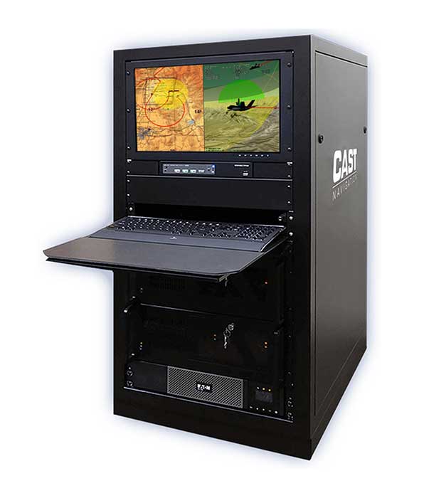
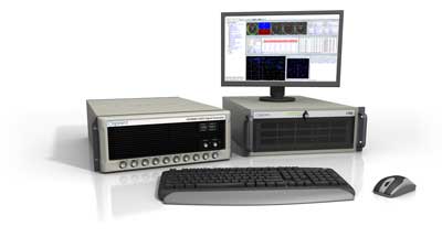
CAST Navigation
VP of Engineering
What is your most recent innovation?
Our latest simulator innovations contain wave-front generation signal technology, which allows you to generate GNSS and interference signals that represent the received signals for each antenna element in a phased array antenna manifold, usually referred to as a controlled radiation pattern antenna (CRPA). Our modular design approach enables users to simulate IMU data commensurate with the wave-front signals for a complete coherent GNSS/IMU simulation that is ideal for stimulating receivers that contain CRPA and IMU capabilities. Our simulators also contain proprietary synchronization technology that allows users to synchronize multiple systems to produce a “wave-front” of GNSS and IMU signals for multiple vehicles, or even an entire fleet.
What is your approach to jamming and spoofing?
CAST Navigations’ family of GNSS simulators are capable of realistically simulating a wide range of suboptimal conditions—such as jamming/spoofing, multipath, RF interference and satellite constellation perturbations—for virtually any commercial or military environment. Our interference signals or “jammers” can be located at any terrestrial location and can be static or dynamic in nature. A distinguishing feature of CAST Navigations’ simulation systems is that our interference signals are phase-controlled and coherent, allowing for proper phase transmission of each signal type for each receiving antenna element. You can also add an INS capability to any of our systems. These types of systems are perfect for testing GNSS and GNSS/INS types of navigation equipment.
What’s coming by 2023?
One of the key trends is the ability to generate M-code (MNSA) signals. Jamming and spoofing are becoming more prevalent, not just to the military but also to consumers. Every day, the military, as well as people like you and me, are starting to encounter more instances of interference that can deny GNSS equipment and even phones the ability to track some GNSS satellites or that transmit incorrect GNSS data, causing receivers to display incorrect position solutions. So, our focus is on products and capabilities that enable our customers to simulate those types of environments and help them to mitigate those kinds of events.
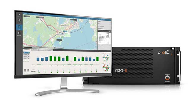
Orolia

Product Manager
What is your most recent innovation?
At Orolia we continue to evolve our innovative software-defined simulator approach. Our most recent innovation is our advanced spoofing option. We have taken our ability to define multiple jamming transmitters, each with their own trajectory and antenna pattern, and added the ability for the transmitters to send spoofing signals as well. By utilizing our capability to run multiple simulations on a single system, we give the user the ability to control every parameter of the generated spoofing constellation(s). The system automatically calculates the signal time of flight and the propagation loss, making this advanced capability powerful and easy to use.
What is your approach to jamming and spoofing?
Simulation of threat environments is a critical component of GNSS receiver testing. As awareness of the impact that jamming and spoofing can have on a GNSS-based system rises, so does the need to test. That is why we have implemented advanced jamming and spoofing options into our Skydel simulator’s core engine. Replication of degraded environments with threats ranging from one to hundreds is possible using the same hardware and software used for generating GNSS signals. No third-party hardware or software is required for complete testing against jamming and spoofing because we feel that this capability should be part of the core system, not an afterthought.
What’s coming by 2023?
In the coming years, we expect to see more requirements for simulation of alternative positioning, navigation, and timing (PNT) signals. As governments and organizations continue to investigate alternate technologies, it will become necessary to simulate low Earth orbit (LEO) PNT, ground-based transmitters, and other signals being considered.
Another growing trend is the adoption of controlled reception pattern antennas (CRPAs) for their anti-jam capabilities. These anti-jam antenna systems can only be tested by specialized simulation systems, so we can imagine these simulation systems being commercialized for a broader market around 2023.
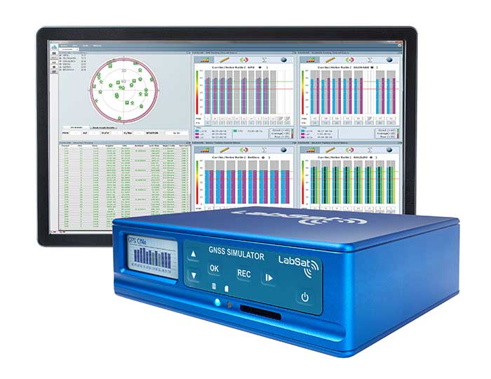
Racelogic

Managing Director
What is your most recent innovation?
Recognizing the need of our customers to test their products with a simple solution that uses the latest GNSS signals, we have updated our SatGen software to create accurate simulations using all satellite data currently being transmitted across the various constellations. We have also optimized the performance of SatGen so that a standard desktop PC can be used to simulate these signals in real time. Also, the simulation can now be driven using an external NMEA stream, allowing full remote control of the trajectory.
What is your approach to jamming and spoofing?
The LabSat 3 Wideband records and replays all available GNSS signals in high fidelity, allowing jamming and spoofing signals to be reproduced accurately on the test bench.
What’s coming by 2023?
With so many employees now working from home due to COVID-19, the pressing concern for many companies developing GNSS technology is how to provide employees with suitable equipment that is required for them to carry out their jobs efficiently away from the office. Usually these employees would utilize the shared resources of a well-equipped office, with experts on hand to help, but working from home has made access to these devices challenging. Due to LabSat 3’s small size, low cost and ease of use, we have seen a significant increase in sales to companies furnishing their employees with a suitable method of testing their GNSS devices while working from home.
With the advent of a new breed of high-performance, low-cost GNSS receiver, many new applications are being developed in new and exciting sectors, utilizing a level of accuracy previously considered too expensive to be a commercial proposition. The number of GNSS engines will therefore increase rapidly in the marketplace, with a corresponding increase in demand for cost-effective signal simulation for test and development.
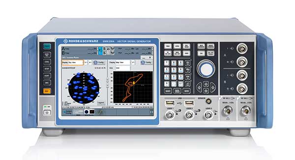
Rohde & Schwarz
Product Manager Signal Generators, Power Meters
What is your most recent innovation?
We further improved multi-frequency, multi-constellation simulation capabilities in our high-end segment. The GNSS high-end simulator R&S SMW200A provides signals for all GNSS frequency bands on a single RF output. A second internal RF path can be used for advanced interferer simulation, testing the receiver’s resilience to spoofing or to address dual-antenna scenarios. This keeps setups simple and compact. When more than two RF paths are required, two or more R&S SMW200A can be operated together in a master/slave configuration. Such setups are required for multi-antenna receiver test applications where the signals’ relative carrier phases are analyzed, like CRPA or attitude determination tests. Our new RF ports alignment software automates alignment of the GNSS signals and guarantees correct amplitude, time and phase relations at the RF inputs of the device under test. We also increased the maximum channel count to more than 600 channels to improve testing of multi-constellation, multi-frequency receivers against multipath, jamming and spoofing.
What is your approach to jamming and spoofing?
Besides our recent innovations, Rohde & Schwarz plans to provide new interference simulation capabilities within the GNSS simulator. This new feature will allow the user to replay recorded jammer signals as well as user-defined waveforms. The R&S Pulse Sequencer software helps with the definition of most complex interferer scenarios.
What’s coming by 2023?
Developments in the field of advanced driver-assistance systems (ADAS) aiming for fully autonomous vehicles raise new challenges for reliable PNT solutions. Simulation of interference and jamming scenarios will hence become important in the automotive market. Antenna arrays have proven suitable to counteract RF interference (RFI) by incorporating spatial-processing techniques and might therefore find greater entry into the automotive market. Test solutions must address requirements for simulating all kinds of intentional and unintentional RFI for multi-constellation, multi-frequency and multi-antenna receivers. Apart from simulating GNSS and interference sources, test solutions for autonomous driving will require several other techniques and signals to be applied or simulated, such as RTK/PPP or outputs from other vehicle sensors to perform sensor fusion.
Spirent Federal Systems

Vice President, Sales
What is your most recent innovation?
Launched in 2018, SimMNSA became the first MNSA simulator to achieve GPS Directorate security approval. The software enables users to simulate true MNSA M-code with real-time code and message generation, removing the constraints imposed by simulator data sets (SDS). SimMNSA v2.0 does even more. It is able to broadcast nominal M-code conditions and recreate SDS-defined events. It incorporates an advanced editor to edit military navigation (MNAV) content, allows users to craft and define scenarios, and much more.
What is your approach to jamming and spoofing?
Spirent offers numerous capabilities for emulating GNSS signals in the presence of interference and spoofing attacks. Our solutions provide accurate, repeatable and quantifiable signals, enabling customers to conduct accurate tests with trusted results. We can test against internally generated interference enabling multiple “fields” of jammers with various interference types; hundreds of interference signals using external IQ blended with simulator-generated GNSS, and Blue Force Electronic Attack jamming waveforms for testing MGUE devices operating in GPS-denied environments. Spoofing capabilities include signal, navigation data and cyber-level attacks via manipulation of up to 12 copies of each primary GNSS constellation, each fully editable; intuitive spoof attack generation via Spirent’s SimSAFE software option — which also allows live sky synchronization/spoofing, and more.
What’s coming by 2023?
Threats to reliable and accurate GNSS navigation and timing are developing rapidly. Fortunately, innovative solutions for resilient PNT are in development and will continue to challenge the industry for years to come. The ability to simulate these threats and the mitigation techniques to overcome them is changing the landscape for the simulator industry. It’s more important than ever to have up-to-date test tools. Robust signals along with frequency and constellation diversity will continue to drive the market in addition to GNSS backup systems, or AltNav. The FCC has certainly presented the GNSS industry with an immense challenge.
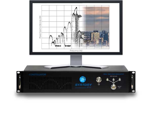
Syntony GNSS

Simulator Activity Manager
What is your most recent innovation?
Yesterday, GPS systems had to “work.” Today, they must work fine. This is the difference, and all equipment vendors have realized this. It is no longer acceptable to have 200 meters or more of error in an urban environment. Because of the extreme complexity of the electromagnetic situation in the GNSS spectrum, making a reliable and precise location system requires more and more powerful and advanced simulators. This is why the GNSS simulator market is booming.
Among the many new features implemented in Syntony’s GNSS simulator this year, two stand out.
First, 1000-Hz hardware-in-the-loop now allows an accurate simulation for high-dynamic receivers (up to more than 100 Gs!), with zero artifact and zero-effective latency. This is the ultimate in trajectory management.
Second, signal computing capacity has made a significant leap forward due to hardware and software optimizations. Constellator can now simultaneously generate up to 660 L1 C/A-equivalent signals. And this level of performance can be unlocked remotely, without a hardware update.
What is your approach to jamming and spoofing?
Simulating a GNSS environment with a set of jamming or spoofing signal sources today is the standard. But what about a simulation of an extremely complex urban scene with 50 or 100 jamming/spoofing sources? The only reasonable solution to implement this would be a massive parallel software-defined radio (SDR)-based simulator solution. This is what Syntony can and will do, thanks to its full software GNSS simulator architecture, which can be distributed on a server farm.
What’s coming by 2023?
A revolution is arriving: the possibility of generating a full GNSS simulation including many hundreds of satellites and signals, in real time and in pure software. This is now possible, and Syntony has demonstrated it with the Constellator. This will change the simulation world. First of all, Moore’s law will bring significant improvements to this domain year after year. More importantly, new systems and services will be possible: massive parallel scenario simulation including jamming and spoofing, floating simulator licenses, software as a service, etc. In this trend, playback machines will be needed, and obviously a strong internet connection will be necessary to download hundreds of gigabytes of I/Q files overnight.
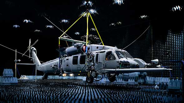
Feature image: Samuel King Jr./United States Air Force