GPS World’s 8th annual Simulator Buyers Guide features tools, devices and software from leading providers.
| CAST NAVIGATION | JACKSON LABS TECHNOLOGY INC. | OROLIA |
|---|
| QASCOM | RACELOGIC | ROHDE & SCHWARZ |
|---|
| SKYDEL | SPIRENT FEDERAL SYSTEMS | TALEN-X |
|---|
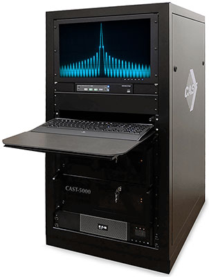
CAST NAVIGATION
CAST-5000 GPS wavefront generator
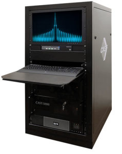
The CAST-5000 produces a single coherent wavefront of GPS RF signals to provide repeatable testing in the laboratory environment or anechoic chamber. The basic system generates four independent, coherent simulations that reference a single point and is upgradeable to support seven elements for CRPA testing. With an intercard carrier- phase error of less than 1 millimeter, the CAST-5000 is extremely accurate.
The system generates a wavefront of GPS when its GPS RF generator cards are operated in a ganged configuration. Each generator card provides a set of GPS satellites coherent with the overall configuration. Several RF generator cards may be utilized together, ensuring phase coherence among the bank of signal generator cards.
The CAST-5000 Controlled Reception Pattern Antenna (CRPA) tester allows a full end-to-end test of the antenna system. The CRPA antenna, antenna electronics and the GPS receiver can be tested as a unit with or without radiating signals.
The CAST-8000 is a new simulator that merges both the CAST-5000 CRPA tester with a CAST-3000 EGI tester.
CAST-5000 Features
- Generates single coherent wavefront of GPS
- 6-DOF motion generation capability
- Complete SV constellation editing
- Post-mission processing via ICD-GPS-150/153
- Differential/relative navigation
- Antenna pattern modeling
- Waypoint navigation
- RAIM events
- Multipath modeling
- Spoofer simulation
- Satellite clock errors
- External trajectory input
- External ephemeris and almanac
- Several iono and tropo models
- Modifiable navigation message
- Modeled selective availability
- Time-tagged satellite events
- Selectable host vehicle parameters
- Directional jamming
www.castnav.com
[email protected]
(978) 858-0130
JACKSON LABS TECHNOLOGY INC.
Micro-Transcoder GPS Simulator/RF-Modulator
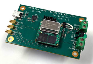
The tiny 1-inch square Micro-Transcoder module allows glueless retrofitting of existing GPS equipment with secure and Assured-PNT (A-PNT) capability. It is the smallest, full-constellation, stand-alone, real-time 10-channel GPS simulator available from JLT. The unit is useful in upgrading existing legacy GPS receivers with external position, navigation and timing references such as INS, CSAC, SAASM, M-code, GNSS, eLoran or other alternative positioning and timing sources by simply replacing the legacy GPS antenna from an existing GPS system with the Micro-Transcoder RF output.
The unit is based on the JLT CLAW GPS Simulator and RSR Transcoder technologies, and includes a general-purpose, stand-alone, full-constellation, 10-channel, real-time GPS simulator with integrated high-stability timing reference, as well as an internal GNSS receiver for monitoring the RF output signal for quality and accuracy. The unit will transmit a standard UTC time, position, velocity and heading GPS L1 C/A RF signal by simply applying 3.3V power to it.
The Micro-Transcoder can also be operated as a generic GPS simulator with built-in GPS Disciplined Oscillator (GPSDO), and is supported by a free Windows application downloadable from the JLT website. The Windows application allows control of all the simulation aspects, creating and storing simulation vector commands and testing user equipment for leap-second and GPS week rollover event compatibility to identify weaknesses in user equipment. The unit does not require a connected PC to function. The Micro-Transcoder is also available mounted onto an evaluation board for easy evaluation. The unit transcodes baseband PNT NMEA signals into a GPS L1 RF signal with typically less than 100-ms latency. UTC 1PPS timing-transfer accuracy to the GPS RF output is typically better than 5 ns. The unit requires only 3.3V to operate, and setup, location and simulation vector file information can optionally be stored in its internal NV memory.
[email protected]
www.jackson-labs.com
(702) 233-1334
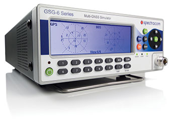
OROLIA
GSG-5/6 Series
All Constellations, All Frequencies
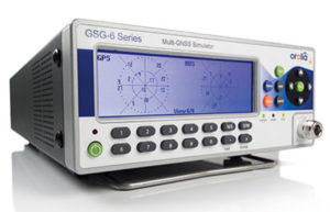
For those responsible for mission-critical PNT applications, the Orolia GSG series of GPS/GNSS simulators is an important tool to evaluate risk for jamming, spoofing or any other threat. Orolia GSG-5/6 series simulators are easy to use, feature-rich and affordable, offering a way to harden GPS-based systems without the limitations of testing from “live sky” signals. The Orolia platform approach allows customers to buy only what they need today and upgrade later. The adaptability of the GNSS RF generation platform can extend to applications for intelligent repeating.
Test Solutions
- Position accuracy and dynamic range/sensitivity
- Simulate movements/trajectories anywhere on or above Earth
- Sensitivity to GPS impairments: loss of satellites, multipath, atmospheric conditions, interference, jamming and spoofing
- Conducted or over-the-air RF
- GPS time-transfer accuracy
- Effect of leap-second transition
- Multi-constellation testing
- Modernization signals/frequencies
- Keyless military SAASM, dual-frequency and survey-grade receiver testing
- Application packages for real-time kinematic (RTK), controlled radiation pattern antennas (CRPA)
- Hardware-in-the-loop (HIL) integration
- Test solutions for eCall and ERA-GLONASS
Infrastructure possibilities include zone-based indoor location (intelligent repeating) and pseudolite applications.
GSG-6 Series 64-channel multi-frequency, advanced GNSS simulator is powerful enough for any cutting-edge test program. GPS, GLONASS, Galileo, Beidou, QZSS and NAVIC (IRNSS) signals are available across multiple frequencies. The GSG-6 is designed for military, research and professional applications.
GSG-5 Series 16-channel multi-constellation L1-band GNSS simulator is designed for commercial development/integration programs. It is for developing commercial products with GNSS capability, and will shorten test programs with confidence.
GSG-51 single-channel signal generator is designed for one purpose — fast, simple go/no-go manufacturing test and validation, ensuring the manufacturing line is operating at full capacity with confidence in quality.
www.orolia.com
[email protected]
+1-585-321-5800
QASCOM
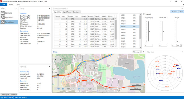
QA707 GNSS and Interference Software Simulator
Specifically designed for testing GNSS interferences and cyber-attacks. QA707 has been designed to test robustness against emerging cyber-threats beyond jamming and spoofing. It allows the creation of scenarios with signal and code jamming, data-level cyber-attacks, denial of service threats, low-level spoofing channels control, and trajectory-controlled spoofing.
Optimal for signal modernization design. Being a flexible software defined radio (SDR) solution, QA707 is also suitable for testing of signal modernization and for the simulation of new signal components. An open API is provided to create specific signals simulation. Particularly, the tool is ready to support the upcoming Galileo Open Service Authentication (OSNMA).
Runs on a standard PC or laptop with USRP or other hardware. QA707 is compatible with several third-party hardware RF up-converters, including National Instruments’ USRP. It also can support customer’s specific hardware through the hardware API interface. Qascom introduces the new frontier of GNSS security testing. QA707 is supported from back office with custom services as well as jamming and spoofing mitigation solutions for receivers and applications. This covers 100% of customer GNSS security needs.
QA707 Main Features
- Multi-constellation (GPS L1, Galileo E1, SBAS L1)
- Galileo OSNMA ready
- RF simulation, binary file dump, signal record and replay
- Support to SDR platforms and open API for custom RF upconverters
- Runtime scenario data UDP stream: motion, channel data, simulated inertial sensor
- Data-level cyber attacks
- Low-level spoofing signals control, trajectory spoofing, signal replay attacks
- Narrowband, wideband, frequency modulated jamming
- Integrity threats: evil waveform, erroneous ephemerides, code/carrier divergence, low satellite signal power, excessive range acceleration
- Built-in editing tools: RF output calibration, RINEX editor, trajectory editor
www.qascom.it
[email protected]
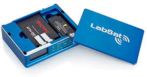
RACELOGIC
LabSat 3 Wideband and Satgen Software
LabSat 3 Wideband
The LabSat 3 Wideband is easy to use, cost-effective and produces extremely low noise, accurate and repeatable signals. Users can record and replay up to three different channels at 56 MHz with a bit depth of up to 3 bits I and 3 bits Q.
The following signals can be recorded and replayed:
- GPS: L1 / L2 / L5
- GLONASS: L1 / L2 / L3
- BeiDou: B1 / B2 / B3
- QZSS: L1 / L2 / L5
- Galileo: E1 / E1a / E5a / E5b / E6
- IRNSS: L5
- SBAS: WAAS, EGNOS, GAGAN, MSAS, SDCM
- L-band GNSS correction services: Terrastar, Veripos, OmniSTAR, StarFire
- 2X CAN, RS232, and digital inputs recorded and replayed tightly synchronized with GNSS data
Small, battery or mains powered and with a removable SSD (up to 4 Tb), LabSat 3 Wideband allows detailed, real-world satellite data to be recorded then replayed on the bench. The rugged enclosure measures a compact 167 x 128 x 46 millimeters and weighs 1.2 kilograms, meaning it can be placed in a backpack and used to reliably record real-world signals in almost any situation.
SatGen Signal Simulation Software
If a user wants to simulate the signals from scratch, Racelogic’s latest SatGen signal simulation software can produce synthesized scenarios containing the full complement of popular GNSS signals: GPS L1, L2C, L5, GLONASS L1, L2, Galileo E1, E5, E6 and BeiDou B1, B2.
SatGen software allows users to quickly create accurate scenarios with their own time, place and trajectory, with any combination of constellation and signal that is currently available or will become available in the near future.
Mark Sampson, LabSat Product Manager
[email protected]
www.labsat.co.uk
ROHDE & SCHWARZ
R&S SMW200A and R&S SMBV100B simulators
Precision-sensitive applications such as autonomous driving, control of unmanned aerial vehicles (UAV), or positioning of aircrafts during landing procedures in coordination with ground-based augmentation systems (GBAS) require that modern GNSS receivers undergo detailed tests before implementation.
Designed to generate highly realistic test scenarios, Rohde & Schwarz signal generators like the R&S SMW200A and the R&S SMBV100B offer a unique approach to generating complex and highly realistic scenarios for testing of GNSS receivers that are able to work with diverse navigational systems such as GPS, GLONASS, Galileo, BeiDou and QZSS/SBAS signals. The R&S SMW200A and the R&S SMBV100B can emulate them all for testing.
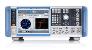
R&S SMW200A
The R&S SMW200A GNSS simulator (pictured above) can be used to produce complex interference scenarios with multiple interferers — all generated within the instrument itself. It can emulate up to 144 GNSS channels and can be equipped with up to four RF outputs. With its ability to simulate multi-constellation, multi-frequency, multi-antenna and multi-vehicle scenarios, the R&S SMW200A is able to cover a variety of high-end GNSS applications.
R&S SMBV100B
The R&S SMBV100B supports the same navigational systems, with access to 24 GNSS channels and one RF output, with the same ability to configure realistic scenarios including obscuration, multipath and atmospheric effects, as well as the specific characteristics of the antenna and the simulated vehicle. An integrated noise and CW interference generator can also be added.
Since the devices do not require an external PC for scenario configuration, all the tests can be created quickly through the user-friendly GUI. Due to all-encompassing instrument options available, both simulators can be set up to fit unique user requirements.
For testing GNSS receivers under controlled and repeatable conditions, the R&S SMW200A and the R&S SMBV100B provide extensive and cost-effective solutions. The platforms are ready to adapt to future requirements and testing of newly implemented GNSS signals.
www.rohde-schwarz.com
[email protected]
+49 89 4129 12345
SKYDEL
SDX is a proven and advanced GNSS simulator based on GPU-accelerated computing and software-defined radio (SDR).
It is available as a complete turnkey system suitable for all GNSS simulation needs, including everything from compact test benches to complete CRPA test systems, such as SDX wavefront and SDX anechoic. Moreover, its software-defined roots enable the selection of cost-effective hardware into configurations that can be repurposed for different projects.
The architecture behind SDX provides real-time simulation of uncompromising accuracy. It features advanced signal customization and supports configurable outputs. IQ data can be generated in, or imported back into, the simulator as well. The API is embedded in the simulator core, enabling deep automation with a few simple clicks, as well as complex scripts developed with popular programming languages.
SDX simulates multiple constellations on multiple frequencies (GPS, Galileo, GLONASS, BeiDou and SBAS) on a large number of channels. Encrypted codes are supported for GPS and Galileo.
The Advanced Jammer module in SDX gives users complete control over interference creation. It is integrated directly into simulation scenarios to enable dynamic jammers (up to 120dB J/S) to interact with GNSS signals.
SDX also allows users to create advanced scenarios suitable for any type of vehicle: antenna patterns (receiver and GNSS SV), LEO/GEO/HEO orbits, multipath, hardware-in-the-loop (HIL), additive pseudorange errors, message modification and corruption, raw logging and more.
It is suitable for the design and validation of GNSS receivers, complex integration, academic research, NAVWAR and test engineering.
SDX is developed and actively supported by Skydel’s engineering teams and worldwide distributors. Skydel offers direct support to clients to ensure prompt deployment and integration, or to review advanced customization requirements.
www.skydelsolutions.com
[email protected]
1-438-239-7924
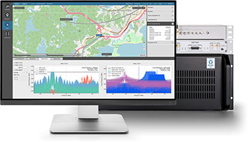
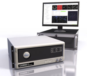
SPIRENT FEDERAL SYSTEMS
GSS9000, SIMMNSA, CRPA Test System, anechoic chamber testing, mid-range testing
Spirent Federal provides GPS/GNSS test equipment that covers all applications, including research and development, integration/verification, and production testing.
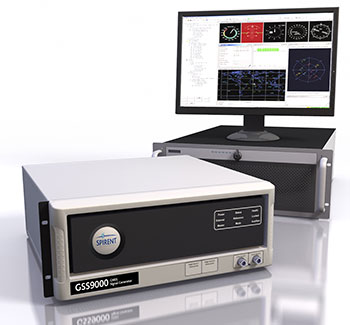
GSS9000. The Spirent GSS9000 Multi-Frequency, Multi-GNSS RF Constellation Simulator is Spirent’s most comprehensive simulation solution. It can simulate signals from all GNSS and regional navigation systems and has a system iteration rate (SIR) of 1000 Hz (1 ms), enabling higher dynamic simulations with more accuracy and fidelity. The GSS9000 supports restricted/classified signals. Users can evaluate the resilience of navigation systems to interference and spoofing attacks, and have the flexibility to reconfigure constellations, channels, and frequencies between test runs or test cases.
SimMNSA. SimMNSA allows authorized users to simulate true M-code for the first time ever. SimMNSA has been successfully delivered to users of the GSS9000 series simulator. SimMNSA has been granted Security Approval by the Global Positioning System Directorate.
CRPA Test System. Spirent’s Controlled Reception Pattern Antenna (CRPA) Test System generates both GNSS and interference signals. Users can control multiple antenna elements. Null-steering and space/time adaptive CRPA testing are both supported by this comprehensive approach.
Anechoic Chamber Testing. Spirent’s GSS9790 Multi-Output, Multi-GNSS RF Constellation Wave-Front Simulator System is a development of the GSS9000. The GSS9790 is a unique solution providing the core element for GNSS applications that require a test system that can be used in both conducted (lab) and radiated (chamber) conditions.
Mid-Range Solutions. Spirent also offers solutions that cater to intermediate GPS/GNSS testing needs. The GSS7000 multi-constellation simulator provides an easy-to-use solution for GNSS testing that can grow with users’ requirements. The GSS6450 RF record & playback system enables replay of a real-world GNSS/GPS test repeatedly in the lab.
Jeff Martin, [email protected]
Kalani Needham, [email protected]
Tyson Gurney, [email protected]
www.spirentfederal.com
(801) 785-1448
[email protected]
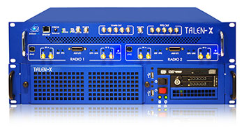
TALEN-X
BroadSim
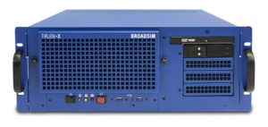
A scalable software-defined simulation platform powered by Skydel’s SDX, capable of generating high-fidelity GNSS and jamming signals simultaneously across multiple constellations and vehicles. Simultaneously simulate every signal below:
- GPS Open Codes: L1 C/A, L1C, L1P, L2P, L2C, L5
- GPS Encrypted Codes: L1/L2 P(Y)-Code, L1/L2 AES M-code, L1/L2 MNSA (Coming soon)
- GLONASS: G1, G2
- Galileo: E1, E5a, E5b
- BeiDou: B1, B2
- SBAS: L1, L5
- Jamming
BroadSim’s software-defined platform includes intuitive user control and APIs; fast development cycles; flexible licensing and upgradability; and no additional hardware needed to maintain.
Forms
Original (4U)
- Rack-mounted 4U simulator used for lab or field testing
- 4 RF outputs (unlimited jamming signals generated on 1)
- 1000-Hz simulation iteration rate
- High-performance processor, GPUs and memory
Anechoic
- Simulation system used for anechoic chamber testing
- 32 RF outputs and 16 dual-frequency antennas
- Automatic antenna mapping
- Automatic time delay and power loss calibration
Wavefront
- Phase coherent simulation system
- Real-time automated phase calibration
- Scalable from 4 to 16 elements
- Supports CRPA and multi-element receiver testing
- Supports jamming and spoofing
Panacea
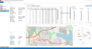
An automated PNT performance and vulnerability test suite that supports up to 32 UUTs (units under test) in real time, from test plan creation to post-test evaluation.
- Time synchronization to live sky
- Compatible with 100+ different GNSS receiver brands
- Create dynamic scenarios with parameters such as jamming patterns, motions, power loss, delays and more.
- Manages receiver communication and standardizes data output for easy analysis, visualization and reporting