Tag: IFEN

  • Antenna Array and Receiver Testing with a Multi-RF Output GNSS Simulator

    Antenna Array and Receiver Testing with a Multi-RF Output GNSS Simulator

    Luck_opener-W

    By Thorsten Lück, Günter Heinrichs, IFEN GmbH, and Achim Hornbostel, German Aerospace Center

    This article discusses the GALANT adaptively steered antenna array and receiver and demonstrates the test scenarios generated with the GNSS simulator. Exemplary results of different static and dynamic test scenarios are presented, demonstrating the attitude determination capabilities as well as the interference detection and mitigation capabilities.

    The vulnerability of GNSS to radio frequency interference and spoofing has become more and more of a concern for navigation applications requiring a high level of accuracy and reliability, for example, safety of life applications in aviation, railway, and maritime environments.In addition to pure power jamming with continuous wave (CW), noise or chirp signals, cases of intentional or unintentional spoofing with wrong GNSS signals have also been reported.

    Hardware simulations with GNSS constellation signal generators enable the investigation of the impact of radio interference and spoofing on GNSS receivers in a systematic, parameterized and repeatable way. The behavior of different receivers and receiver algorithms for detection and mitigation can be analyzed in dependence on interference power, distance of spoofers, and other parameters. This article gives examples of realistic and advanced simulation scenarios, set up for simulation of several user antennas simultaneously.

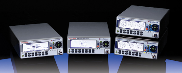
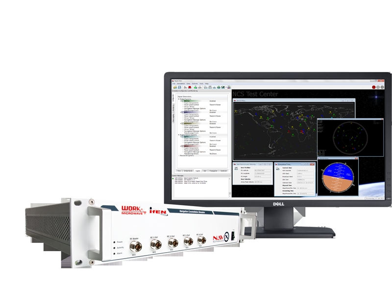
    The professional-grade high-end satellite navigation testing and R&D device used here is powerful, easy to use, and fully capable of multi-constellation / multi-frequency GNSS simulations for safety-of-life, spatial and professional applications. It provides all L-band frequencies for GPS, GLONASS, Galileo, BeiDou, QZSS, SBAS and beyond in one box simultaneously. It avoids the extra complexity and cost of using additional signal generators or intricate architectures involving several hardware boxes, and offers full control of scenario generation. A multi-RF capable version provides up to four independent RF outputs and a master RF output that combines the RF signal of each of the up to four individual RF outputs.

    Each individual RF output is connected to one or more “Merlin” modules (the core signal generator module for one single carrier) allowing simulation of up to 12 satellites per module. Because of the flexible design of the Merlin module, each one can be configured to any of the supported L-band frequencies.

    As one chassis supports up to nine individual Merlin modules, different Multi-RF combinations are feasible:

    • two RF outputs with up to four modules each
    • three RF outputs with up to three modules each
    • four RF outputs with up to two modules each.

    With these configurations, the user can simulate different static or dynamic receivers or even one receiver with multiple antennas, covering such challenging scenarios as ground networks, formation flying or use of beam-forming antennas.

    As the user is free to assign each individual module to a dedicated simulated antenna, the user could also employ up to nine modules to simulate nine different carrier signals for one single antenna using the master RF output, thus simulating the complete frequency spectrum for all current available GNSS systems in one single simulation.

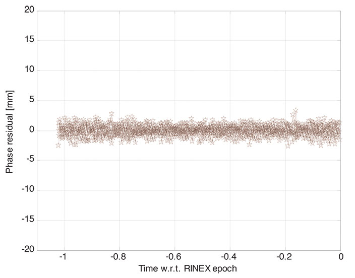
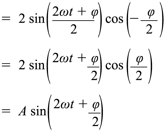
    All modules are calibrated to garantee a carrier phase coherency of better than ±0.5°. Figure 1 shows the output at the RF master of two modules assigned to the same carrier but with a phase offset of 180°.

    Figure 1. Carrier-phase alignment of the high-end simulator with six modules compared to the first module.
    Figure 1. Carrier-phase alignment of the high-end simulator with six modules compared to the first module.

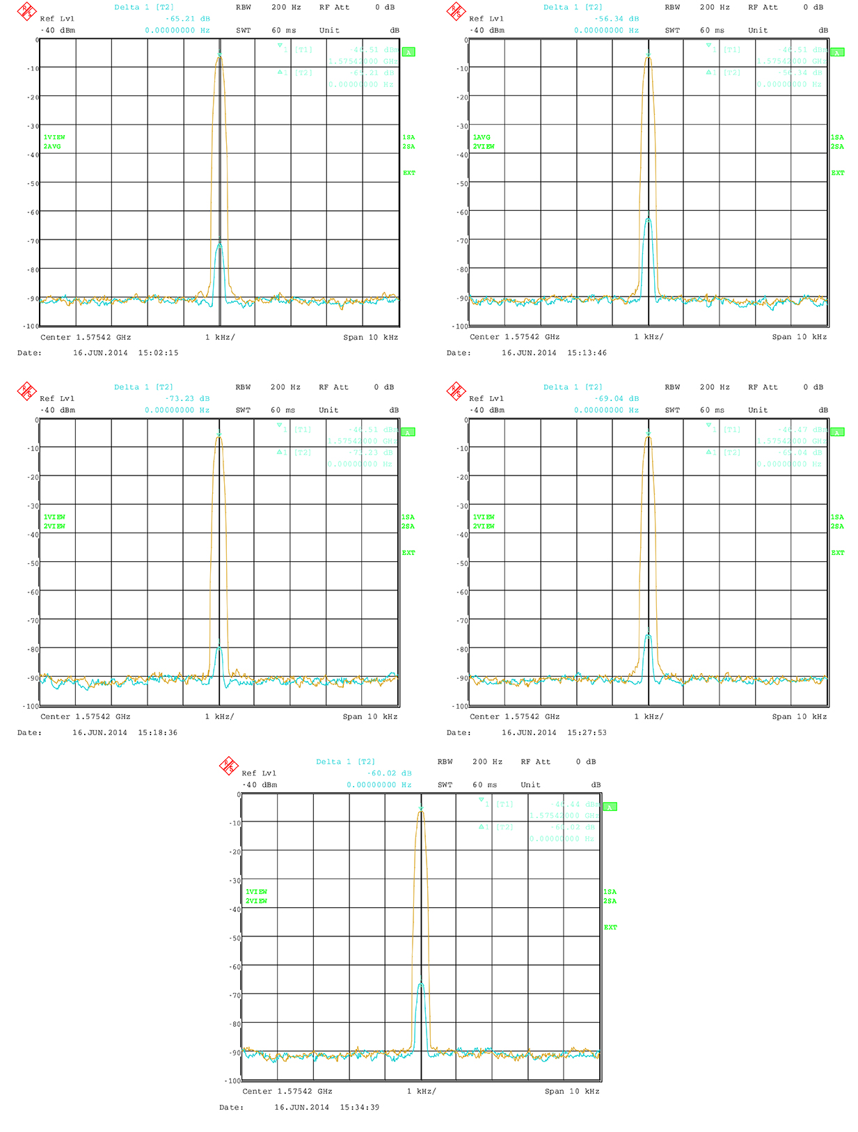
    Theoretically, the resulting signal should be zero because of the destructive interference. In practice, a small residual signal remains because of component tolerance, small amplitude differences and other influences. Nevertheless the best cancellation can be seen at this point. The phase accuracy can now simply be estimated from the measured power level of the residual signal:

    Luck-Eq1  (1)

    Luck-Eq2 (2)

    with

    Luck-Eq2b

    This means that the sum of two sine waves with the same frequency gives another sine wave. It has again the same frequency, but a phase offset and its amplitude is changed by the factor A. The factor A does affect the power level. If φ is 180° then A is 0, which means complete cancellation.

    So A shows the power of the resulting signal relative to the single sine wave. It can also be transformed to dB:
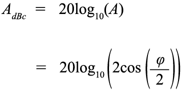
    Luck-Eq3 (3)

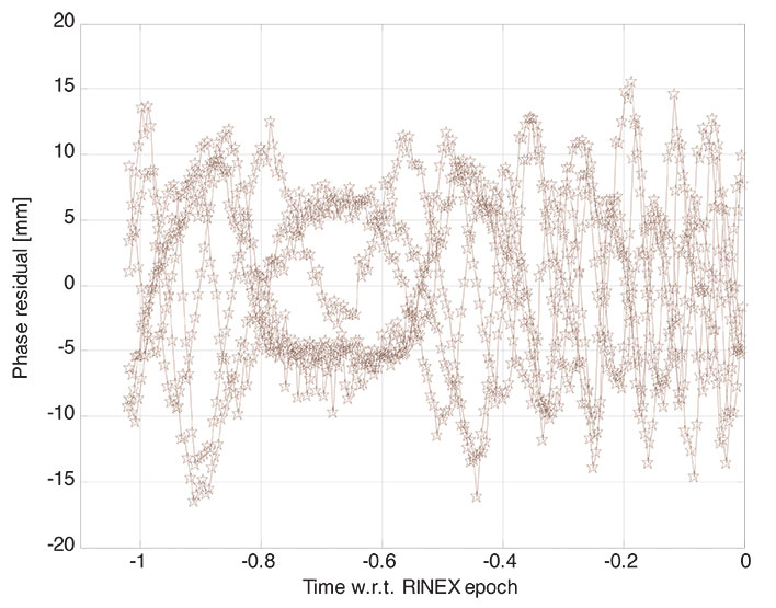
    Figure 2 shows the carrier suppression as a function of carrier phase offset with a pole at 180ϒ.

    Figure 2. Carrier suppresion as a function of phase delay.
    Figure 2. Carrier suppresion as a function of phase delay.

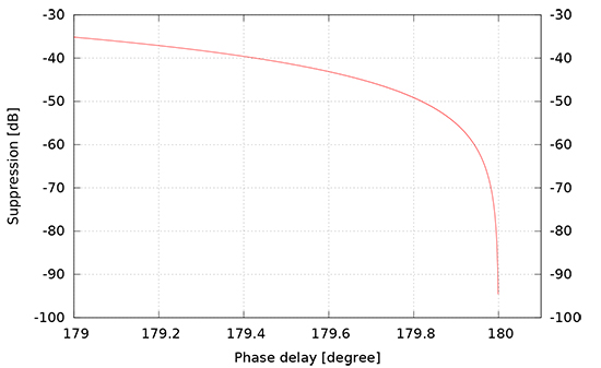
    The factory calibration aligns the modules to a maximum of 0.5ϒ misalignment. The measured suppresion therefore shall be better than 41.18 dBc. In practice, the residual signal is also caused by other influences, so that the actual phase alignment can be expected to be much better.

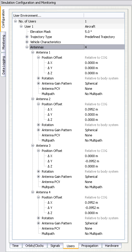
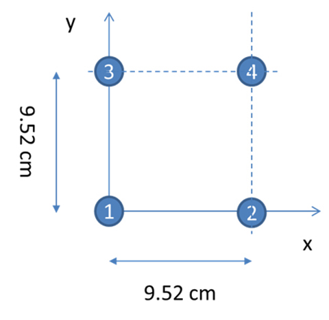
    With four RF outputs, the received signal of a four element antenna can be configured very easily. Figure 3 shows the dialog to configure a four-element antenna with the geometry shown in Figure 4. Note that the antenna elements are configured in the body-fixed system with the x-axis to front and the y-axis to the right (inline with a north-east-down, NED, system when facing to north), while the geometry shown in Figure 4 follows an east-north-up (ENU) convention.

    Figure 3. Configuration of individual antennas per receiver.
    Figure 3. Configuration of individual antennas per receiver.
    Figure 4. Geometry of the GALANT four-element phased-array antenna (view from top).
    Figure 4. Geometry of the GALANT four-element phased-array antenna (view from top).

    The following sections give an overview of multi-antenna systems and discuss results from a measurement campaign of the German Aerospace Center (DLR) utilizing the simulator and the DLR GALileo ANTenna array (GALANT) four-element multi-antenna receiver.

    Multi-Antenna Receivers

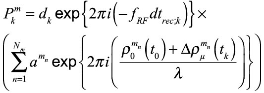
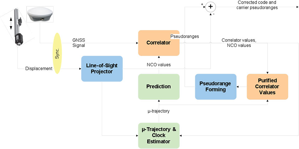
    Multi-antenna receivers utilize an antenna array with a number of antenna elements. The signals of each antenna element are mixed down and converted from analog to digital for baseband processing. In the baseband, the signals received by the different antenna elements are multiplied with complex weighting factors and summed. The weighting factors are chosen in such a way that the received signals from each antenna element cancel out into the direction of the interferers (nulling) and additionally, for advanced digital beamforming, such that the gain is increased into the direction of the satellites by forming of individual beams to each satellite. Because all these methods work with carrier phases, it is important that in the simulation setup, the signals contain the correct carrier phases at the RF-outputs of the simulator corresponding to the user satellite and user-interferer geometry, and the position and attitude of the simulated array antenna.

    Figure 5 presents the geometry of a rectangular antenna array with 2×2 elements and a signal s(t) impinging from direction (ϕ, θ).

    Figure 5. Parallel wavefront impinging on a rectangular array with 2x2 elements.
    Figure 5. Parallel wavefront impinging on a rectangular array with 2×2 elements.

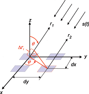
    The spacings of the elements dx, dy are typically half a wavelength, but can also be less. The range difference for antenna element i relative to the reference element in the center of the coordinate system depends on the incident direction (ϕ, θ) and the position (m=0,1, n=0,1) of the element within the array:

    Luck-Eq4 (4)

    The corresponding carrier phase shift is:

    Luck-Eq5 (5)

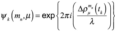
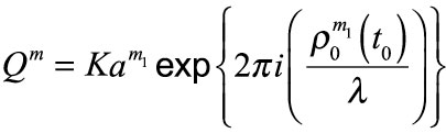
    For CRPA and adaptive beam forming applications, the differential code delays may be neglected if they are small compared to the code chip length. However, it is essential that the carrier phase differences are precisely simulated, because they contain the information about the incident direction of the signal and are the basis for the array processing in the receiver. For instance, the receiver can estimate the directions of arrival of the incident signals from these carrier phase differences.

    Now we consider a 2×2 array antenna. It can be simulated with the simulator with four RF outputs, where each output corresponds to one antenna element. In the simulator control software, a user with four antennas is set up, where the position of each antenna element is defined as an antenna position offset relative to the user position. In this approach, both differential code and carrier delays due to the simulated array geometry are taken into account, because the code and carrier pseudoranges are computed by the simulator for the position of each antenna element. However, the RF hardware channels of the receiver front-end may have differential delays against each other, which may even vary with time. If the direction of the satellites and interferers shall be estimated correctly by the receiver algorithms, a calibration signal is required to measure and compensate these differential hardware delays.

    For the real antenna system, a binary phase-shift keying (BPSK) signal with zero delay for each antenna channel is generated by the array receiver and fed into the antenna calibration port. For the simulation, this calibration signal must also be generated by the constellation simulator.

    In a simple way, a satellite in the zenith of the user antenna can be simulated, which has the same distance and delay to all antenna elements. Unfortunately, this simple solution includes some limitations to the simulated position and attitude of the user, because the user position must be at the Equator (if a “real” satellite is simulated in form of a geostationary satellite) and the antenna must not be tilted.

    With a small customization of the simulator software, these limitations could be overcome. Figure 6 shows how to set up the generation of a reference signal. This reference signal can either be simulated as a transmitter directly above the user position, which follows the user position and thus allows also simulations offside the Equator, or simulated as a zero-range signal on all RF outputs, neglecting any geometry, which is the preferred method. The latter one is more or less identical to the reference/calibration signal generated by the receiver itself.

    Figure 6. Configuration of a modulated reference signal.
    Figure 6. Configuration of a modulated reference signal.

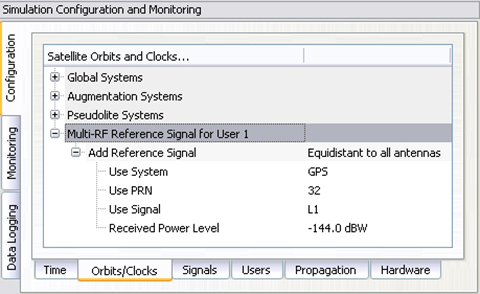
    The power level of this signal is held constant and is not affected by any propagation delay or attenuation simulated by the control center.

    Attitude Determination

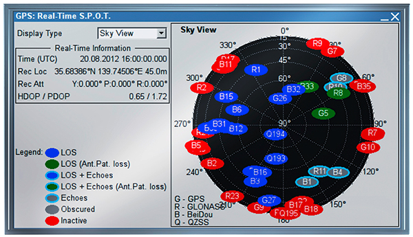
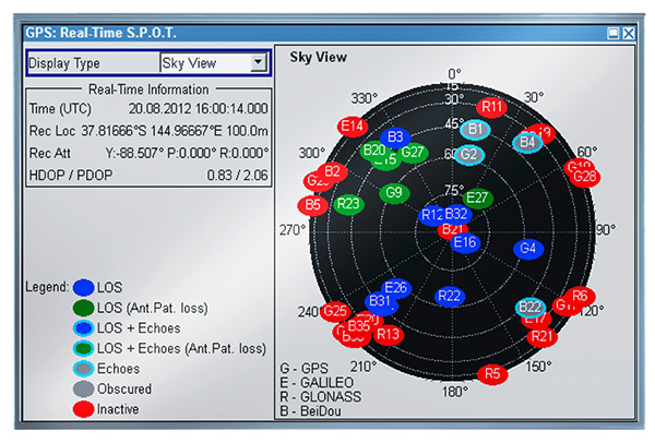
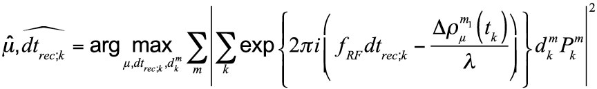
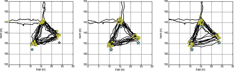
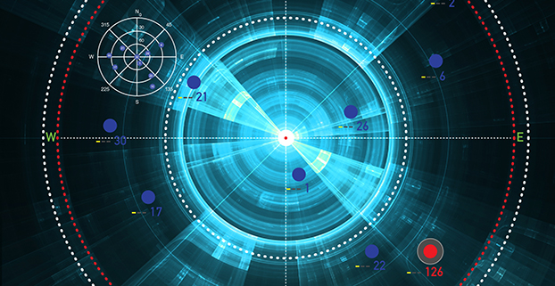
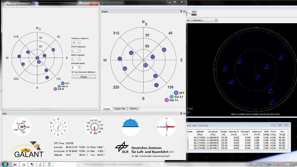
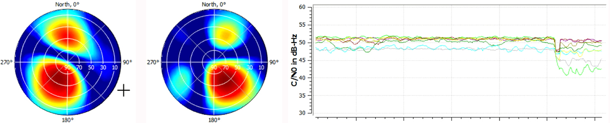
    According to Figure 5, the phase difference measured between antenna elements is a function of the direction of arrival (DoA). Thus, the DoAs of the incident signals can be estimated from the phase differences. In the GALANT receiver, the DoAs are estimated by an EPSPRIT algorithm after correlation of the signals. Compared with the (known) positions of the GNSS satellites, this allows the estimation of the antenna array attitude. Figure 7 shows the sky-plot of simulated satellites as seen at receiver location (simulated on the right; reconstructed by the receiver from the decoded almanac in the middle and the DoA on the left). By comparison of the estimated DoAs of all satellites and the skyplot from the almanac, the attitude of the antenna is estimated (left). In addition, the attitude angles simulated by the simulator is given (right).

    Figure 7. Simulating and estimating attitude with a multi-element antenna.
    Figure 7. Simulating and estimating attitude with a multi-element antenna.

    Simulation of Interference

    It is possible to simulate some simple types of interference. Possible interference scenarios are:

    Wideband Noise. By increasing the power of a single satellite of the same or another GNSS constellation, a wideband pseudo-noise signal can be generated. Using a geostationary satellite also enables simulating an interference source at low elevations and constant position. Use of power-level files also allow generation of scenarios with intermittent interference (switching on and off the interference) with switching rates up to 5 Hz.

    CW or Multi-Carrier IF. By disabling the spreading code and navigation message, a CW signal can be generated. The simulator also allows configuration of subcarrier modulations. Without spreading code (or to be precise with a spreading code of constant zero) the generated signal will consist of two carriers symmetrically around the original signal carrier (for example, configuring a BOC(1,1) signal will create two CW signals at 1.57542 GHz ± 1.023 MHz, thus producing “ideal” interferer for the Galileo E1 OS signal.)

    Depending on the number of Merlin modules per RF output, interference to signal ratios up to 80 dB could be realized, limited by a dynamic range of 40 dB within one module and additional 40 dB range between two modules. However, the maximum power level of one individual signal is currently limited to -90 dBm. If only one channel per module is used, the maximum power level of this single signal can be increased by another 18 dB (for example, by using one module solely for interference generation and another module for GNSS simulation).

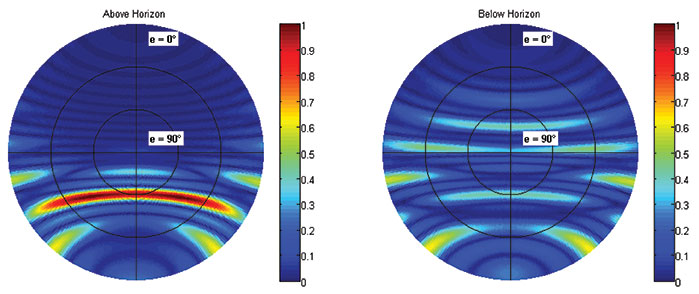
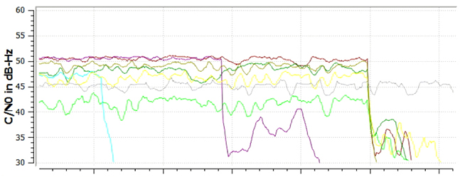
    Figure 8 shows the simulated geometry for an interference scenario based on wideband noise generated by a geostationary satellite, producing –90 dBm signal power at the receiver front end. The interference source is very near to the direction of PRN 22 with a jammer power of –90 dBm, resulting in a jammer to signal ratio of J/S = 25 dB.

    Figure 8. Geometry for the wideband noise interference scenario.
    Figure 8. Geometry for the wideband noise interference scenario.

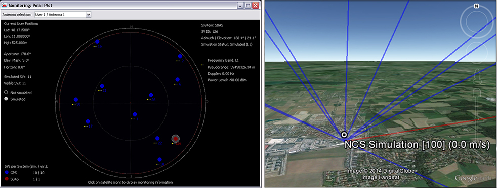
    Figure 9 shows the two-dimensional antenna pattern as a result of the beam-forming before and after switching on the interferer. The mitigation algorithm tries to minimize gain into the direction of the interferer. As this also decreases gain into the direction of the intended satellite, the C/N0 drops by approximately 10 dB for PRN 22, because its main beam is shifted away from the interference direction. For satellites in other directions, the decrease in C/N0 is less: compare Figure 9 with Figure 10. However, the receiver still keeps tracking the satellite. After switching of beamforming, the signal is lost.

    Figure 9. Beamforming for PRN 22 (light green line in lower plot) to mitigate for interference.
    Figure 9. Beamforming for PRN 22 (light green line in lower plot) to mitigate for interference.
    Figure 10. Tracking is lost after switching off beamforming for individual channels (light blue, purple) and all channels (at the end of the plot).
    Figure 10. Tracking is lost after switching off beamforming for individual channels (light blue, purple) and all channels (at the end of the plot).

    Simulation of Spoofing

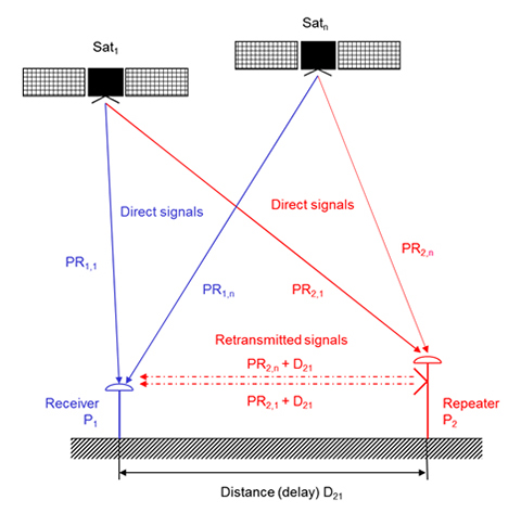
    The simulation of a spoofing signal requires twice the resources as the real-world scenario, as every “real” LoS-signal must also be generated for the spoofing source. A simulation of an intentional spoofer who aims to spoof a dedicated position in this context is, however, very similiar to the simulation of a repeater ([un-]intentional interferer) device:

    The repeater (re-)transmits the RF signal received at its receiver position. A receiver tracking this signal will generate the position of the repeater location but will observe an additional local clock error defined by the processing time within the repeater and the travel time between repeater and receiver position. A correct simulation for a multi-antenna receiver therefore has to superpose the code and carrier range as observed at the repeater location (considering geometric range between the transmit antenna of the repeater and the individual antenna elements) with the code and carrier ranges at the receiver location.

    Instead of the location of the repeater P2, however, any intended location Px could be used to simulate an intelligent spoofer attack (Figure 11).

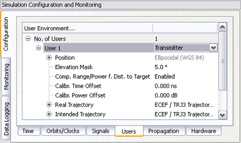
    The simulator can generate such scenarios by configuring the position of the (re-)transmitting antenna and the intended position (for example, the position of the repeater). By calculating the difference between the real receiver position and the position of the transmitting antenna, the additional delay and free-space loss can be taken into account. The user may also configure the gain of the transmit antenna and the processing time within the repeater. Currently, this setup does only support one “user” antenna to be simulated. However, this feature combined with multi-antenna support will enable the simulator to simulate repeater or intelligent spoofer attacks in the future (Figure 12). To distinguish the “real” signal from the “repeated” signal, the “repeated” signal could be tagged as a multipath signal. This approach would allow simulation of the complete environment of “real” and “repeated” GNSS signals in one single simulator.

    Figure 11. Geometry of repeater/spoofer and GNSS receiver.
    Figure 11. Geometry of repeater/spoofer and GNSS receiver.
    Figure 12. Simulator’s capability to simulate a repeater.
    Figure 12. Simulator’s capability to simulate a repeater.

    Manufacturers

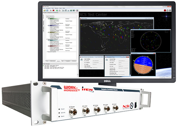
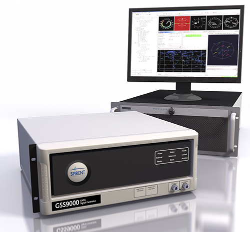
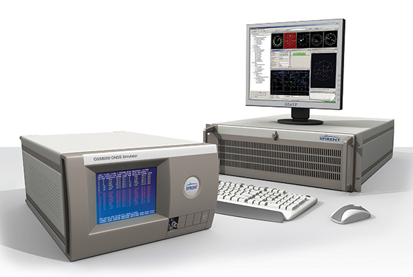
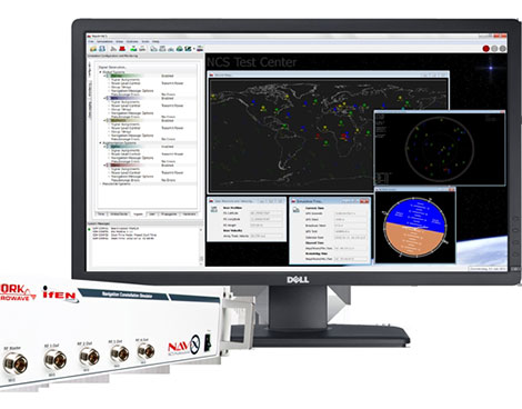
    The simulator producing the results described here is the NavX-NCS from IFEN GmbH. The simulator is valuable laboratory equipment for testing not only standard or high-end single-antenna GNSS receivers, but also offers additional benefit for multi-antenna GNSS receivers like the DLR GALANT controlled reception pattern antenna system.

    The GNSS constellation simulator offers up to four phase-coherent RF outputs, allowing the simulation of four antenna elements with two carrier frequencies, each utilizing one single chassis being 19 inch wide and 2 HU high.

    Simulation of intentional and unintentional interference is a possible feature of the simulator and allows receiver designers and algorithm developers to test and enhance their applications in the presence of interference to identify, locate and mitigate for interference sources.


    Thorsten Lück studied electrical engineering at the universities in Stuttgart and Bochum. He received a Ph.D. (Dr.- Ing.) from the University of the Federal Armed Forces in Munich in 2007 on INS/GNSS integration for rail applications. Since 2003, he has worked for IFEN GmbH, where he started as head of R&D embedded systems in the receiver technology division. In 2012 he changed from receiver development to simulator technologies as product manager of IFEN’s professional GNSS simulator series NavX-NCS and head of the navigation products department.

    Günter Heinrichs is the head of the Customer Applications Department and business development at IFEN GmbH, Poing, Germany.  He received a Dipl.-Ing. degree in communications engineering in 1988, a Dipl.- Ing. degree in data processing engineering and a Dr.-Ing. degree in electrical engineering in 1991 and 1995, respectively. In 1996 he joined the satellite navigation department of MAN Technologie AG in Augsburg, Germany, where he was responsible for system architectures and design, digital signals, and data processing of satellite navigation receiver systems. From 1999 to April 2002 he served as head and R&D manager of MAN Technologie’s satellite navigation department.

    Achim Hornbostel joined the German Aerospace Center (DLR) in 1989 after he received his engineer diploma in electrical engineering from the University of Hannover in the same year. Since 2000, he has been a staff member of the Institute of Communications and Navigation at DLR. He was involved in several projects for remote sensing, satellite communications and satellite navigation.  In 1995 he received his Ph.D. in electrical engineering from the University of Hannover. His main activities are in receiver development, interference mitigation and signal propagation.

  • 2015 Simulator Buyers Guide

    2015 Simulator Buyers Guide

    Special Section, March 2015. Download a PDF of this section, with the Simulator Product Showcase.

    CAST Navigation

    CAST-SGX GPS Satellite Simulator

    sgx_high-W
    The SGX GPS satellite signal simulator from CAST Navigation. Photo: CAST Navigation

    The SGX GPS satellite signal simulator from CAST Navigation provides the user with dynamic, repeatable GPS RF signals for use in the laboratory or in the field for a wide range of GPS applications. The SGX simulator is housed in a portable, lightweight, handheld enclosure measuring 7 x 11 x 3 inches and weighing just over 4 pounds.

    The SGX is lightweight and portable, operates on AC or battery power, and features 16 channels of L1 C/A and P codes. Based on CAST’s technology that has been developed for use in the company’s larger military products, it is extremely accurate and repeatable.

    The SGX is controlled via an intuitive touchscreen interface that allows the user to select, start, and stop scenarios, change screen views, and change satellite RF power levels while a scenario is running. Three test scenarios are delivered with the simulator.

    XGEN Plus Scenario Generation Software. This software gives the user the ability to generate custom scenarios for use with the SGX. The software allows for complete control over GPS almanac, ephemeris, and all satellite error sources.

    The user can select from a variety of vehicle types and simulate static or dynamic motion. The user can also employ antenna gain patterns and vehicle silhouettes if desired. The user can generate a customized high precision six-degree-of-freedom trajectory simply by defining a mission profile that is based on raw maneuvers, waypoints, Google Maps or a combination of these maneuver types.The new scenarios can be downloaded via USB port or SD card interfaces.

    CAST has been in the GPS simulation and support business for more than 30 years, designing, developing, manufacturing, and integrating innovative GPS/INS simulators and associated test equipment for government, military, prime vendor, and consumer markets.

    www.castnav.comphone: 978 858-0130; email: [email protected]

    Cobham AvComm (formerly Aeroflex)

    GPSG-1000 — Portable GPS/Galileo/SBAS Positional Simulator

    Aeroflex GPSG-1000: Portable GPS/Galileo/SBAS Positional Simulator
    Aeroflex
    GPSG-1000: Portable GPS/Galileo/SBAS Positional Simulator Photo: Galileo

    Designed to be a versatile yet affordable satellite simulator, the GPSG-1000 is proving to be a vital instrument used by those validating and testing GNSS receivers in a variety of applications within the transportation, consumer electronics, aerospace and military industry segments, to name a few. 

    The GPSG-1000 is a single carrier, multi-channel GPS/Galileo simulator that is portable and ruggedized so it can be safely and confidently deployed in a variety of outdoor and indoor environments. The unit is available in a 6- or 12-channel configuration, and supports the following GNSS signals: L1, L1C, L2C, L5, E1, E5, E5a, E5b and SBAS (WAAS and EGNOS). 

    The GPSG-1000 can be directly connected to a GNSS receiver under test. It can also simulate actual “open-sky” situations whereby the unit can generate its signals through the included antenna coupler system that isolates and transmits to the UUT’s antenna(s). Utilizing an integrated GPS receiver, the GPSG-1000 simulates actual time of day and date as well as the real constellation that would be available for navigation at that specific point in time. Multiple almanacs and route files can be saved to the GPSG’s memory, thereby enabling current and past history dynamic motion, constellation environment creation/recreation and other significant troubleshooting capabilities. During any given static or dynamic simulation, space vehicle parametrics and health can be user controlled.

    The GPSG-1000 features a touchscreen user interface that can be remotely hosted via an integrated Ethernet port. The unit uses a rechargeable, Lithium Ion battery enabling hours of untethered use, and can also be used while the battery is recharging. 

    ats.aeroflex.com; phone: (316) 522-4981 or (800) 835-2352; email: [email protected]

    IFEN Inc.

    NavX-NCS Professional GNSS Simulator

    NavX-NCS Essential GNSS Simulator

    NCSPRO-MULTI_SW-W
    The NavX-NCS Professional GNSS Simulator by IFEN. Photo: IFEN

    The absolute flexibility of the NavX-NCS Professional GNSS Simulator allows it to be configured with up to 108 channels and all of the following signals:

    • GPS L1/L2/L5 C/A & P code and L2C
    • GLONASS G1/G2 standard & high accuracy codes
    • Galileo E1/E5/E6 (BOC/CBOC/AltBOC)
    • BeiDou B1/B2/B3
    • SBAS L1/L5 (WAAS, EGNOS, MSAS, GAGAN)
    • QZSS L1 & L1-SAIF
    • IMES

    The user is enabled to assign signals freely to any of the RF modules fitted to the simulator. This allows the same hardware to be used in a range of different configurations.

    Signals may be added by software license with no need to return the hardware for upgrade.

    Up to four independent RF outputs may be fitted, enabling the user to simulate multiple antenna locations simultaneously (allowing simulation of multiple antennas on one vehicle, multiple vehicles simultaneously, a mixture of static locations and mobile vehicles, and multiple antenna elements for Controlled Reception Pattern Antenna [CRPA] testing).

    The comprehensive and easy-to-use Control Center operating software allows the operator to quickly create realistic test scenarios for effective testing of user equipment.

    IFEN also offers the NavX-NCS Essential GNSS Simulator, which is available with 21 or 42 channels and is capable of simulating GPS L1 (including SBAS L1), GLONASS G1, Galileo E1, BeiDou B1, QZSS L1, and IMES. The simulator is also supplied with Control Center operating software for comprehensive scenario generation.

    www.ifen.com

    For USA and Canada: Mark Wilson; phone: 951-739-7331; email: [email protected]

    Racelogic

    LabSat 3 Triple Constellation Simulator

    Racelogic LabSat 3. Photo: RaceLogic
    RaceLogic LabSat 3. Photo: RaceLogic

    LabSat 3 from Racelogic is a low cost, stand-alone, battery powered, multi-constellation RF record-and-replay device, designed to assist GNSS engineers in the development and testing of their products.

    With its small size and all-in-one design, LabSat 3 makes it easier than ever to collect raw satellite data in the same environment that end users experience in everyday use. This enables repeatable and realistic testing to be carried out under controlled conditions.

    LabSat 3 doesn’t need to be connected to a PC in order to record live-sky GNSS signals. With one-touch recording to SD card and a two-hour battery life, it can be used in any outdoor location to create real-world scenarios, for eventual replay back in the lab. As well as being able to simultaneously record or replay GPS, GLONASS, BeiDou, QZSS, Galileo, and SBAS signals, it can log CAN Bus, serial, or digital data, embedded alongside the satellite information. This additional information can then be replayed alongside the GNSS output, with synchronization to within 60 ns. A 1PPS signal can also be generated using the internal GPS receiver.

    LabSat 3 can be used as a replay system out of the box with a set of 60 pre-recorded scenarios supplied as part of the package, recorded from various locations around the globe. Additionally, SatGen software, a demo version of which is available from the LabSat website, allows for
    scenario generation of user-defined trajectories, with precise control over velocity, heading, height, and constellation profiles. Routes are also easily created in Google Maps, and the software also supports NMEA and KML file import. SatGen gives test engineers the ability to develop their products using simulations that would be difficult or impossible to record due to geographic location or safety constraints.

    LabSat 3 is available as a record and replay, or replay-only version; either one, two, or three constellation types generate a single, dual, or triple constellation file.

    LabSat is currently used by many leading manufacturers of GPS chipsets, portable navigation devices, smartphones, and by major car companies in their test, development and production processes.

    www.labsat.co.uk; phone: +44 (0)1280 823803

    Rohde & Schwarz

    R&S SMBV100A: GNSS Simulator in Vector Signal Generator

    The R&S SMBV100A: GNSS Simulator in Vector Signal Generator.
    The R&S SMBV100A: GNSS Simulator in Vector Signal Generator. Photo: R&S

    The GNSS simulator in the vector signal generator R&S SMBV100A is designed for development, verification and production of GNSS chipsets, modules and receivers. The simulator supports all possible scenarios, from simple setups with individual, static satellites all the way to flexible scenarios generated in real time with up to 24 dynamic GPS, GLONASS, Galileo, BeiDou and QZSS satellites.

    • GNSS simulator with support of GPS L1/L2 (C/A and P code), GLONASS L1/ L2, Galileo E1, BeiDou and QZSS L1, including hybrid constellations.
    • Real-time simulation of realistic constellations with up to 24 satellites and unlimited simulation time.
    • Flexible scenario generation including moving scenarios, dynamic power control and atmospheric modeling.
    • Configuration of realistic user environments, including obscuration and multipath, antenna characteristics and vehicle attitude.
    • Static mode for basic receiver testing using signals with zero or constant Doppler shift.
    • Support of Assisted GNSS (A-GNSS) test scenarios, including generation of assistance data for GPS, GLONASS, Galileo, BeiDou and QZSS.
    • Real-time external trajectory feed for hardware in the loop (HIL) applications.
    • High signal dynamics, simulation of spinning vehicles and precision code (P-code) simulations to support aerospace and defense applications.
    • Enhanced simulation capabilities for aerospace applications by supporting ground-based augmentation systems (GBAS).
    • Support of other digital communications and radio standards in the same instrument.

    www.rohde-schwarz.comemail: [email protected]

    Spectracom

    Afforable, Flexible and User-Friendly GNSS Simulators

    The Spectracom family of simulators.
    The Spectracom family of simulators. Photo: Spectracom

    Spectracom GNSS Simulators support test and development programs from simple manufacturing tests to multi-output testing across the diverse ecosphere of industries relying on GNSS technology. Spectracom’s innovation allows users of any skill level full control over the GNSS constellation, vehicle motion/attitude and signal path complications such as atmospherics and multipath to develop complex scenarios. Typical test conditions include:

    • Clock errors
    • Data errors
    • “Real-world” motion from embedded Google Maps
    • In-band noise generation
    • Multipath
    • Signal obstructions calculated from 3D building models
    • “Current time” simulation
    • Real-time HIL testing
    • Easy synchronization for multi-output testing
    • Automative download of the current almanac
    • Antenna pattern effects
    • Inertial sensor testing
    • Assisted GNSS testing

    No dedicated PC is required. Scenarios are run and managed from the front panel, SCPI commands, or any PC/tablet via a web interface. Users can select a flexible, field upgradeable Spectracom simulator, and then purchase the software options they need.

    GSG-6 Series multi-frequency, advanced GNSS simulator is powerful enough for any cutting-edge test program. GPS, GLONASS, Galileo, Beidou, QZSS and IRNSS signals are available across multiple frequencies. The GSG-6 is designed for military, research or professional applications.

    GSG-5 Series multi-constellation L1-band GNSS simulator is designed for commercial development/integration programs. If a user is developing commercial products with GNSS capability, the GSG-5 will shorten test programs with confidence.

    GSG-51 single channel signal generator is designed for one purpose — fast, simple go/no-go manufacturing test and validation, ensuring the manufacturing line is operating at full capacity with confidence in quality.

    www.spectracom.comemail: [email protected]; phone: 585-321-5800

    Spirent Federal Systems

    GNSS Simulators

    Spirent's GSS9000 constellation simulator.
    Spirent’s GSS9000 constellation simulator. Photo: Spirent

    Spirent provides simulators that cover all applications, including research and development, integration/verification and production testing.

    GSS9000. The newly released Spirent GSS9000 multi-frequency, multi-GNSS RF constellation simulator can simulate signals from all GNSS and regional navigation.  The GSS9000 offers a four-fold increase in RF signal iteration rate (SIR) over Spirent’s GSS8000 simulator. The GSS9000 SIR is 1000 Hz (1 ms), enabling higher dynamic simulations with more accuracy and fidelity. It includes support for restricted and classified signals from the GPS and Galileo systems, as well as advanced capabilities for ultra-high dynamics. It can evaluate resilience of navigation systems to interference and spoofing attacks, and has the flexibility to reconfigure constellations, channels and frequencies between test runs or test cases.

    Hardware changes can be done in the field, supported by the new on-board calibrator module. The GSS9000 is extensible and can support the widest range of carriers, ranging codes and data streams for the Galileo, GPS, GLONASS, and BeiDou systems, as well as regional/augmentation systems. Multi-antenna/multi-vehicle simulation, for differential-GNSS and attitude determination, and interference/jamming and spoofing testing are also supported.

    CRPA Test System. Spirent’s Controlled Reception Pattern Antenna (CRPA) Test System generates both GNSS and interference signals. Users can control multiple antenna elements. Null-steering and space/time adaptive CRPA testing are both supported by this comprehensive approach.

    GSS6425. The Spirent GSS6425 RPS quickly and simply records complex real-world RF environments, capturing both GNSS signals and atmospheric/interference effects. These environments can then be replayed repeatedly to the hardware software under test, reducing project, travel and engineering costs.

    www.spirentfederal.comJeff Martin, Director of Sales; Kalani Needham, Sales Manager; email: [email protected]; phone: 801-785-1448; fax: 801-785-1294

  • GATE Facility Recertified as Galileo Test Bed

    The German Galileo test and development infrastructure GATE has been recertified to serve as a Galileo open‐air test laboratory, for receiver integrity testing (RAIM) for safety‐of‐life (SoL) applications, and for Galileo SIS ICD conformance of signal characteristics and signal quality.

    The GATE facility, in Berchtesgaden, is operated by IFEN GmbH. Certification was conducted by TÜV SÜD, an international service corporation focusing on consulting, testing, certification and training.

    GATE consists of eight transmitting stations that emit Galileo signals in the GATE test area in Berchtesgaden, as well as two monitoring stations that receive and process these signals.

    For application tests, it is essential for GATE to provide constant Galileo specifications for tests, including position accuracy, signal spectrum and navigation data. This is necessary for both test types: tests with the eight “GATE satellites” only and tests with simultaneously usage of the already-existing Galileo satellites in orbit.

    The compliance to the specification was verified by the company NavCert GmbH from Braunschweig, Germany, in a recertification of the GATE test bed. Compared to a full certification, taking place every three years, a recertification only verifies the compliance to the specification by the use of random inspections though tests in GATE.

    The recertification also includes an audit of the operation processes of the operating company IFEN GmbH. Here, the implementation and adherence to process procedures for GATE operation were verified. This includes questions such as whether a sufficiently technical skilled team is available for operating GATE, if the performed application tests are documented in a reproducible way, and how the GATE team handles non‐conformances to the specification and improvements to the system.

    With finalization of the recertification work, the GATE certificate was extended by TÜV SÜD to January 2016. Because of this, GATE customers can rely on the independent verification of the GATE test and development environment for upcoming testing activities, IFEN said.

    As an add‐on, customers of IFEN’s NavX‐NCS GNSS simulator benefit from the recertification by obtaining a confirmation from an independent organization (TÜV Süd), reassuring the functionality of GPS and Galileo signal characteristics and signal quality as per SIS ICD, IFEN said.

  • ION GNSS+ 2014: IFEN Inc.

    Mark Wilson, IFEN Inc., demonstrates the company’s new XS3 software receiver – which succeeds the scientific GNSS software-receiver SX-NSR – at the the 2014 ION GNSS+ Conference September 9-12 in Tampa, Florida.

  • IFEN Officially Launches SX3 Software Receiver

    IFEN Officially Launches SX3 Software Receiver

    IFEN-SX3_with_chart-W Photo: IFEN
    Photo: IFEN

    IFEN has launched the SX3 receiver. The company’s previous scientific software receiver, the SX‐NSR, was subject to major upgrades, while the respective hardware front-end was completely redesigned. Together, they build the new SX3 GNSS software receiver.

    IFEN’s most important innovation of the year was introduced at the ION GNSS+ Conference September 9-12 in Tampa, Florida.

    One of the SX3’s key features is four RF frequency bands, which can be split into a maximum of eight sub-bands per unit. This enhances the bandwidth to a full 55 MHz per RF band, offering additional signal power, especially in E5 band. The new USB 3.0 port empowers a unrivaled data transfer rate that makes a maximal bit-quantization of up to 8-bit possible — for every single stream.

    The additional power is compressed into a significantly smaller and lighter hardware chassis than before. Among other options, a dual antenna-input feature can be ordered as well as an OXCO clock. (Standard equipment of the SX3 GNSS software receiver is a precise temperature-controlled oscillator.)

    The proofed difference correlator notably ruggedizes acquisition and tracking of any navigation satellite signals. Polyfit tracking reduces measurement noise through averaging (such as code/carrier measurements). (See “Innovation: Software GNSS Receiver.”) Accordingly, vector tracking improves the tracking of weak signals in degraded environments and the reacquisition of “lost” satellites.

    Just like its predecessor, it is also able to act as a framework for a customer’s own signal processing algorithms. “Customers can fully concentrate on their applications instead of dealing with potentially obscure code when using open source,” said Product Manager Bernhard Riedl. “Our professional support is specifically dedicated to scientific work as well as SX3’s capability for additional customizations. SX3 is far more than just a COTS product. This makes IFEN’s new SX3 scientific software receiver a mighty powerful tool for research and development.”

  • 2014 Simulator Buyers Guide

    2014 Simulator Buyers Guide

    In GPS World’s annual Simulator Buyers Guide, we feature simulator tools, devices, and software from six prominent companies. Also available as a downloadable PDF.


    CAST Navigation

    CAST-SGX GPS Satellite Simulator

    sgx_high-W

    The new SGX GPS satellite signal simulator from CAST Navigation provides the user with dynamic, repeatable GPS RF signals for use in the laboratory or in the field for a wide range of GPS applications. The SGX simulator is housed in a portable, lightweight, handheld enclosure measuring 7 x 11 x 3 inches and weighing just over 4 pounds.

    The SGX replaces the CAST-SIMCOM simulator, a 17- inch, 50-pound simulator. The SGX is lightweight and portable, operates on AC or battery power, and features 16 channels of L1 C/A and P codes. Based on CAST’s technology that has been developed for use in the company’s larger military products, it is extremely accurate and repeatable.

    The SGX is controlled via an intuitive touchscreen interface that allows the user to select, start, and stop scenarios, change screen views, and change satellite RF power levels while a scenario is running. Three test scenarios are delivered with the simulator.

    XGEN Plus Scenario Generation Software. This optional software gives the user the ability to generate custom scenarios for use with the SGX. The software allows for complete control over GPS almanac, ephemeris, and all satellite error sources.

    The user can select from a variety of vehicle types and simulate static or dynamic motion. The user may also employ antenna gain patterns and vehicle silhouettes if desired. The user may generate a trajectory by defining a total mission profile using a six-degree-of-freedom model. The new scenarios can be downloaded via USB port or SD card interfaces.

    CAST has been in the GPS simulation and support business for more than 30 years, designing, developing, manufacturing, and integrating innovative GPS/INS simulators and associated equipment for government, military, prime vendor, and consumer markets.

    www.castnav.com
    phone: 978 858-0130
    email: [email protected]

    IFEN Inc.

    NavX-NCS Professional GNSS Simulator
    NavX-NCS Essential GNSS Simulator

    NCSPRO-MULTI_SW-W

    The absolute flexibility of the NavX-NCS Professional GNSS Simulator allows it to be configured with up to 108 channels and all of the following signals:
    •    GPS L1/L2/L5 C/A & P code and L2C
    •    GLONASS G1/G2 standard & high accuracy codes
    •    Galileo E1/E5/E6 (BOC/CBOC/AltBOC)
    •    BeiDou B1/B2
    •    SBAS L1/L5 (WAAS, EGNOS, MSAS, GAGAN)
    •    QZSS L1 & L1-SAIF
    •    IMES

    The user is enabled to assign signals freely to any of the RF modules fitted to the simulator. This allows the same hardware to be used in a range of different configurations.

    Signals may be added by software license with no need to return the hardware for upgrade.

    Up to four independent RF outputs may be fitted, enabling the user to simulate multiple antenna locations simultaneously (allowing simulation of multiple antennas on one vehicle, multiple vehicles simultaneously, a mixture of static locations and mobile vehicles, and multiple antenna elements forControlled Reception Pattern Antenna [CRPA] testing).

    The comprehensive and easy-to-use Control Center operating software allows the operator to quickly create realistic test scenarios for effective testing of user equipment.

    IFEN also offers the NavX-NCS Essential GNSS Simulator, which is available with 21 or 42 channels and is capable of simulating GPS L1 (including SBAS L1), GLONASS G1, Galileo E1, BeiDou B1, QZSS L1, and IMES. The simulator is also supplied with Control Center operating software for comprehensive scenario generation.

    www.ifen.com
     
    For USA and Canada
    Mark Wilson
    phone: 951-739-7331
    email: [email protected]
    For Rest of World
    Dr. Guenter Heinrichs
    phone: +49-8121-2238-20
    email: [email protected]

    RaceLogic

    LabSat 3

    LabSat3_on-Hand-SD-Screen-W

    LabSat 3, the latest generation of GNSS simulators from Racelogic, is a low cost, stand-alone, battery powered, multi-constellation, RF record and replay device designed to assist GNSS engineers in the development and testing of their products. With its small size and all-in-one design, LabSat 3 makes it easier than ever to collect raw satellite data in the same environment that end users experience in everyday use. This enables repeatable and realistic testing to be carried out under controlled conditions.

    LabSat 3 doesn’t need to be connected to a PC to record live-sky GNSS signals. With one-touch recording to SD card and a two-hour battery life, it can be used in any outdoor location to create real-world scenarios, for eventual replay back in the lab. As well as recording GPS, GLONASS, BeiDou, QZSS, Galileo, and SBAS signals, it can simultaneously log CAN bus, serial, or digital data, embedded alongside the satellite information. This additional information can then be replayed alongside the GNSS output, with synchronization to within 60 ns. A 1 PPS signal can also be generated using the internal GPS receiver.

    LabSat 3 can be used as a replay system out of the box with a set of pre-recorded scenarios supplied as part of the package, recorded from various locations around the globe. SatGen software, a free version of which is included with LabSat 3, allows for scenario generation of user-defined trajectories, with precise control over velocity, heading, height, and constellation profiles. Routes are also easily created in Google Maps, and the software also supports NMEA and KML file import. SatGen gives the test engineer the ability to develop a product using simulations that would be difficult or impossible to record due to geographic location or safety constraints.

    LabSat 3 is available in four variants: replay only, or record and replay, of a single channel — one of GPS/Galileo/SBAS/QZSS, GLONASS, or BeiDou; and replay only, or record and replay, of dual channels — two of GPS/Galileo/SBAS/QZSS, GLONASS, or BeiDou.

    LabSat is currently used by many leading manufacturers of GPS chipsets, portable navigation devices, smartphones, and by major car companies in their test, development, and production processes.

    www.labsat.co.uk; phone: +44 (0)1280 823803

    Rohde & Schwarz

    R&S SMBV100A: GNSS Simulator on Vector Signal Generator

    Rohde-Schwarz-Beidou-W

    Rohde & Schwarz extends the functionality of the R&S SMBV100A vector signal generator by adding BeiDou/Compass capability to its integrated GNSS simulator. With the R&S SMBV-K107 option, the GNSS simulator now covers the BeiDou standard as well as the GPS, Galileo and GLONASS satellite navigation systems.

    The new option allows users to generate real-time scenarios with up to 24 BeiDou satellites. R&S SMBV-K107 supports all possible BeiDou orbits and can therefore even simulate satellites that are not yet in orbit. It also supports hybrid scenarios with GPS, Galileo, or GLONASS satellites. A software update makes it easy to upgrade existing GNSS simulators for BeiDou. No hardware modifications are required.

    The R&S SMBV100A permits users to quickly define their own satellite scenarios to test GNSS receivers under diverse conditions. A wide range of options are available for simulating realistic effects such as signal obscuration and multipath propagation. These scenarios can now be configured for BeiDou as well.

    This inexpensive solution is one of the few on the market that does not require an external PC for testing receivers and components of satellite-based navigations systems. In addition to GNSS signals, the R&S SMBV100A can simulate mobile radio, wireless, and radio standards, allowing users to test several functions with a single instrument.

    The new R&S SMBV-K107 option is now available from Rohde & Schwarz.

    www.rohde-schwarz.com
     
    email: [email protected]

    Spectracom

    Configurable, Upgradeable GNSS Simulators

    GSG_Family-SPECTRACOM-W

    Spectracom multi-channel, multi-frequency GSG Series GPS/GNSS Signal Simulators are designed for research, development and manufacturing. They provide powerful, affordable, and easy-to-use application-specific GNSS testing solutions allowing users to simulate virtually any condition through built-in and user-defined scenarios. The simulators now feature expanded capabilities and a flexible, field upgradeable design that allows users to select only the features needed for a specific application, upgrade when necessary.

    The GSG 5 and 6 Series simulators are portable and fully operational via front panel, web-based remote control (Ethernet, USB, GPIB), or SCPI protocol. The models include GSG StudioView PC Software to build, edit, and manage complex scenarios and trajectories. Advanced simulation features include: SBAS (WAAS, EGNOS, GAGAN, MSAS), multipath scenarios, interference detection and mitigation, white-noise generation, and trajectories. The new features and capabilities can be added to any GSG-5 or GSG-6 purchased since June 2012.

    GSG-6 Series Multi-Frequency, Advanced GNSS Simulator
    •    Up to 64 channels and 4-frequencies simultaneously
    •    GPS, GLONASS, Galileo, BeiDou
    •    Sync multiple units for testing hundreds of signals
    •    L1, L2, L2C, L5, E1, E5, B1; [E6, B2, B3 capable HW, with FW upgrade available in the future]
    •    P-code, pseudo P(Y) in L1 and L2
    •    Add-ons for real-time scenarios, record and playback, Assisted-GNSS, RTK/Differential measurements, high velocity
    •    Fully upgradable to future constellations and signals

    GSG-5 Series Multi-Channel, Advanced GNSS Simulator
    •    4, 8 or 16 channels
    •    GPS, GLONASS, Galileo, BeiDou
    •    L1, E1, B1
    •    Upgradeable to more channels and frequencies

    GSG-51 Low Cost Single Channel GPS Signal Generator
    •    1-channel GNSS tester for fast, simple manufacturing test and validation
    •    Fully upgradeable to GSG-5 and 6 series

    www.spectracom.com
     
    email: [email protected]; phone: 585-321-5800

    Spirent Federal Systems

    GNSS Simulators

    GSS8000-W

    Spirent provides simulators that cover all applications, including research and development, integration/verification, and production testing.

    GSS8000 (pictured). Spirent’s flagship simulator, the GSS8000, is fully approved for Y-code, SAASM, AES M-code and SDS M-code testing. Spirent provides options and configurations for testing GNSS interference effects and interference mitigation techniques, such as integrated GPS/inertial testing, CRPA testing, and jamming/anti-jam simulation.

    Spirent has delivered simulators that produce legacy signals as well as modernized signals such as 2C, L5, and L1C. In addition to GPS, systems can include GLONASS L1/L2, Galileo, and Beidou-2, plus SBAS (WAAS, MSAS, and EGNOS) and Japan’s Quasi-Zenith Satellite System (QZSS).

    CRPA Test System. Spirent’s Controlled Reception Pattern Antenna (CRPA) Test System generates both GPS L1/L2 and interference signals; multiple GSS8000 chassis may be combined to coherently control up to seven antenna elements. Null-steering and space/time adaptive CRPA testing are both supported by this comprehensive approach.

    GSS7790. Spirent’s GSS7790 Multi-Output Simulation System allows the signal from each satellite to be mapped to a separate RF output. These signals can then be fed to individual transmit antennas, which, when suitably deployed in an anechoic chamber, replicate the spatial diversity of satellite and jammer signals incident on the receiver antenna. Additional flexibility is offered as the signal is further split into its GPS L1 and L2 components, as appropriate.

    www.spirentfederal.com
     
    Jeff Martin, Director of Sales
    Kalani Needham, Sales Manager
    email: [email protected]
    phone: 801-785-1448; fax: 801-785-1294


  • Spirent’s SimSAFE Fights Signal Vulnerability

    Spirent’s SimSAFE Fights Signal Vulnerability.
    Spirent’s SimSAFE Fights Signal Vulnerability.

    By Tracy Cozzens

    Spirent Communications now offers SimSAFE, a software solution that simulates legitimate GNSS constellations along with spoofed or hoax signals to evaluate receiver resilience and help develop counter measures.

    Hoax or spoofing attacks work by mimicking genuine GNSS signals, which mislead GNSS receivers.  The military and critical infrastructure — such as wireless networks, banking, and utilities — are especially interested in being able to detect and reject spoofing attacks.

    “GNSS signal vulnerability is becoming a significant issue,” said John Pottle, marketing director of Spirent’s Positioning Division.  “The industry is beginning to talk more about vulnerability and how we actually think about categorizing the threat — what approaches are there to evaluate performance in the presence of interference signals? If you’re a developer, what approaches are there to clean up your performance? You’ll see us at Spirent being quite a bit more vocal about these areas in the coming months.”

    SimSAFE was developed in conjunction with Qascom, a small organization of half a dozen GNSS signal security and authentication experts headed by Oscar Pozzobon, who served as the chief solutions architect for SimSAFE. Pozzobon contributed his knowledge of GNSS security and vulnerabilities, which were then integrated into the SimSAFE system.

    SimSAFE provides a means of emulating a spoofing attack, and then monitoring a receiver under attack to evaluate mitigation strategies and countermeasures.

    “SimSAFE really gets into details on how a receiver reacts in the presence of the hoax signals,” Pottle said. “By really understanding that, really getting into how is the receiver is acting and reacting, you can understand better how your receiver is likely to behave, and tune it up.”

    The SimSAFE laboratory-based test solution is fully controllable, so that users can evaluate a receiver’s response to a wide range of spoofing attacks. As Pottle put it, when fed both authentic and spoofed signals, “What’s the receiver going to see? It’s going to see the authentic signals, it’s going to see a couple of spoofed signals. And you can play around with the spoofed signals — that’s the controllable bit. While this is happening, the detector module within SimSAFE monitors and reports the receiver’s response to the attacks. At its most simple, that’s the power of SimSAFE.”

    SimSAFE is aimed not only at receiver developers, a core audience of Spirent’s, but at anyone trying to build a system that may be subject to intentional interference, such as in the military or critical infrastructure. “Those people are starting to ask questions about what should I be worried about? What kind of an attack might I be open to? How can I be sure, if I’ve got a choice of three or four receivers, that I’m going to choose one that meets my needs in terms of resilience to intentional interference?” Pottle said. “Our belief is that SimSAFE will allow people to evaluate different receivers and strategies for mitigating spoofing attacks, and therefore help them to build the right level of resilience in their systems.”

    SimSAFE is available in two variants. SimSAFE Simulated uses the simulator for all signals, both satellite and spoofed, using one or more channels for the spoofed signal.

    Instead of a simulator, SimSAFE Live pulls authentic signals from sky with an antenna, so the user has the full power of the simulator to generate a much broader range of spoofing attacks. “The clever bit is aligning the spoofed signal with the real signal, getting the timing and frequency synced up,” Pottle said.

    Spirent is also working on other technologies to mitigate spoofing, including work with interference signals from ground-based transmitters, adaptive antenna lab-based tests, and integration with inertial sensors, such as in military jets.

    SimSAFE’s signal control capabilities.
    SimSAFE’s signal control capabilities.
  • ESA Awards Contract to IFEN to Develop Advanced GNSS Signal Test Bed

    A contract to design and to deliver an advanced multi-GNSS constellation signal simulator and interface environment testbed was awarded by the European Space Agency (ESA) to IFEN GmbH on October 28, 2013. This contract is concluded in the context of the Signal Test Bed (SIGTB) activities of the European GNSS Evolution Programme (EGEP).

    In addition to addressing the second generation of Galileo, which is planned to provide higher accuracy and signal robustness, the GNSS Signal Test Bed will include the following capabilities:

    • Flexible adaptability to all signal and message standards, whatever the future may bring.
    • Extensive investigation of intentional signal interferences.
    • Testing of GNSS signal performance in newly evolving standards.
    • Generation of even more realistic test scenarios that include background and intentional interference.
    • Refined scenarios of various distortions of GNSS signals.
  • Innovation: Under Cover

    Innovation: Under Cover

    Synthetic-Aperture GNSS Signal Processing

    By Thomas Pany, Nico Falk, Bernhard Riedl, Carsten Stöber, Jón O. Winkel, and Franz-Josef Schimpl

    GPS World photo
    INNOVATION INSIGHTS by Richard Langley

    A SYNTHETIC APERTURE? WHAT’S THAT? Well, an aperture in optics is just a hole or opening through which light travels. Those of us into photography know that the amount of light reaching the camera’s imaging sensor is controlled by the shutter speed and the size of the lens opening or aperture (called the f-stop). And a correct combination of the aperture setting and shutter speed results in a correct exposure.  For an optical telescope, its aperture is the diameter of its main, light-gathering lens or mirror. A larger aperture gives a sharper and brighter view or image.

    In the radio part of the electromagnetic spectrum, the term aperture refers to the effective collecting (or transmitting) area of an antenna. The gain of the antenna is proportional to its aperture and its beamwidth or resolution is inversely proportional to it.

    Astronomers, whether using optical or radio telescopes, often seek higher and higher resolutions to see more detail in the objects they are investigating. Conventionally, that means larger and larger telescopes. However, there are limits to how large a single telescope can be constructed. But by combining the light or radio signals from two or more individual telescopes, one can synthesize a telescope with a diameter equal to the baseline(s) connecting those telescopes. The approach is known as interferometry. It was first tried in the optical domain by the American physicist Albert Michelson who used the technique to measure the diameter of the star Betelgeuse. Radio astronomers developed cable- and microwave-connected interferometers and subsequently they invented the technique of very long baseline interferometry (VLBI) where atomic-clock-stabilized radio signals are recorded on magnetic tape and played back through specially designed correlators to form an image. (VLBI has also been used by geodesists to precisely determine the baselines between pairs of radio telescopes even if they are on separate continents.)

    A similar approach is used in synthetic-aperture radar (SAR). Mounted on an aircraft or satellite, the SAR beam-forming antenna emits pulses of radio waves that are reflected from a target and then coherently combined. The different positions of the SAR, as it moves, synthesize an elongated aperture resulting in finer spatial resolution than would be obtained by a conventional antenna.

    But what has all of this got to do with GNSS? In this month’s column, we take a look at a novel GNSS signal-processing technique, which uses the principles of SAR to improve code and carrier-phase observations in degraded environments such as under forest canopy. The technique can simultaneously reject multipath signals while maximizing the direct line-of-sight signal power from a satellite. Along with a specially programmed software receiver, it uses either a single conventional antenna mounted, say, on a pedestrian’s backpack for GIS applications or a special rotating antenna for high-accuracy surveying. Want to learn more? Read on.


    “Innovation” is a regular feature that discusses advances in GPS technology andits applications as well as the fundamentals of GPS positioning. The column is coordinated by Richard Langley of the Department of Geodesy and Geomatics Engineering, University of New Brunswick. He welcomes comments and topic ideas.


    Over the past few years, we have been developing new GNSS receivers and antennas based on an innovative signal-processing scheme to significantly improve GNSS tracking reliability and accuracy under degraded signal conditions. It is based on the principles of synthetic-aperture radar. Like in a multi-antenna phased-array receiver, GNSS signals from different spatial locations are combined coherently forming an optimized synthetic antenna-gain pattern. Thereby, multipath signals can be rejected and the line-of-sight received signal power is maximized. This is especially beneficial in forests and in other degraded environments.

    The method is implemented in a real-time PC-based software receiver and works with GPS, GLONASS, and Galileo signals. Multiple frequencies are generally supported.

    The idea of synthetic-aperture processing is realized as a coherent summation of correlation values of each satellite over the so-called beam-forming interval. Each correlation value is multiplied with a phase factor. For example, the phase factor can be chosen to compensate for the relative antenna motion over the beam-forming interval and the resulting sum of the scaled correlation values represents a coherent correlation value maximizing the line-of-sight signal power. Simultaneously, signals arriving from other directions are partly eliminated.

    Two main difficulties arise in the synthetic-aperture processing. First, the clock jitter during the beam-forming interval must be precisely known. It can either be estimated based on data from all signals, or a stable oscillator can be used. In one of our setups, a modern oven-controlled crystal oscillator with an Allan variance of 0.5 × 10⁻¹³ at an averaging period of 1 second is used. Second, the precise relative motion of the antenna during the beam-forming interval must be known. Again it can be estimated if enough sufficiently clean signals are tracked. The antenna trajectory is estimated directly from the correlator values as shown later in this article. In more severely degraded environments, the antenna may be moved along a known trajectory. We are developing a rotating antenna displacement unit. (see FIGURE 1). The rotational unit targets forestry and indoor surveying applications. The relative motion of the antenna is measured with sub-millimeter accuracy.

    FIGURE 1. Artist’s impression of the synthetic-aperture GNSS system for surveying in a forest.
    FIGURE 1. Artist’s impression of the synthetic-aperture GNSS system for surveying in a forest.

    After beam-forming, the code pseudoranges and the carrier phases are extracted and used in a conventional way. That is, they are written into Receiver Independent Exchange (RINEX) format files and standard geodetic software can be used to evaluate them. In the case where the artificial movement antenna is used, the GNSS signal processing removes the known part of the movement from the observations, and the observations are then like those from a static antenna. As a result, common static positioning algorithms, including carrier-phase ambiguity fixing, can be applied. The presented method therefore prepares the path for GNSS surveying applications in new areas. An important point is the mechanical realization of the antenna movement. This has to be done in a cost-efficient and reliable way. Lubrication-free actuators are used together with magnetic displacement sensors. The sensors are synchronized to the software receiver front end with better than 1 millisecond accuracy. The rotating antenna uses slip rings to connect the antenna elements. The rotating antenna can also be used to map the received signal power as a function of elevation and azimuth angles. This is beneficial for researchers. For example, it could be used to estimate the direction of arrival of a spoofing signal or to determine which object causes multipath in an indoor environment. For the latter purpose, the rotating antenna can be equipped with left-hand and right-hand circularly polarized antennas on both ends of the rotating bar. The rotating antenna is mounted on a geodetic tripod. See Further Reading for reports of initial studies of the rotating antenna.

    Tracking Modes

    The synthetic-aperture tracking scheme can be extended to different user-motion schemes or sensor-aiding schemes allowing a wide range of applications. This is reflected in the algorithm implementation within the modular structure of the software receiver. The base module “µ-trajectory & Clock Estimator” in Figure 2 prepares the synthetic-aperture tracking scheme. Different implementations derive from this base class. Each derived module is used for a different user motion scheme and makes use of a different sensor.

    FIGURE 2. Different µ-trajectory motion estimators used by the synthetic-aperture processing.
    FIGURE 2. Different µ-trajectory motion estimators used by the synthetic-aperture processing.

    Basically, the modules differ in the way they estimate the relative antenna motion over the beam-forming interval. This relative motion is called the µ-trajectory. Usually the µ-trajectory covers time spans from a few hundreds of milliseconds to a few seconds.

    The µ-trajectories have the following characteristics:

    • The pedestrian motion estimator does not rely on any sensor measurements and fits a second-order polynomial into the user µ-trajectory of a walking pedestrian. A second-order polynomial is good for representing the motion for up to a quarter of a second.
    • The sensor input to the rotating antenna estimator is the relative angular displacement of the rotating antenna. The estimator estimates the absolute direction, which is stable in time. Thus the number of µ-trajectory parameters equals one.
    • The vertical antenna motion estimator retrieves the vertical position of the antenna and does not estimate any µ-trajectory parameters. Only clock parameters are estimated.
    • Finally, the inertial navigation estimator uses accelerometer and gyro measurements and estimates the 3D user motion. The µ-trajectory parameters consist of accelerometer biases, the gyro biases, attitude errors, and velocity errors. The estimation process is much more complex and exploits the timely correlation of the parameters.

    Signal Processing Algorithm

    Two kinds of (related) carrier-phase values occur in a GNSS receiver: the numerically controlled oscillator (NCO) internal carrier phase  ocarrot1  and the carrier phase pseudorange ocarrot, which is actually the output of the receiver in, for example, RINEX  format files. Both are a function of time t and when expressed in radians are related via Equation (1):

    Inno-eq1    (1)

    Here, fo denotes the receiver internal nominal intermediate frequency (IF) at which all signal processing takes place. The output carrier-phase pseudorange ocarrot is an estimate of the true carrier-phase pseudorange , which, in turn, relates to the geometric distance to the satellite by the following standard model:

    inno-eq2   (2)

    This model applies to each signal propagation path separately; that is, a separate model can be set up for the line-of-sight signal and for each multipath signal. In Equation (2), λ denotes the nominal carrier wavelength in meters, ρ(t) is the geometric distance in meters between transmitting and receiving antennas, fRF is the nominal carrier frequency in hertz, dtsat(t) and dtrec(t) are the satellite and receiver clock errors in seconds, N is the carrier-phase ambiguity, and T(t) contains atmospheric delays as well as any hardware delays in meters. Here, no measurement errors are included, because we are considering the relationship between true values.

    Defining now a reference epoch t0, we will describe a procedure to obtain an improved carrier-phase estimate  for this epoch using data from an interval [t0TBF, t0]. The beam-forming interval TBF can be chosen to be, for example, 0.2–2 seconds but should be significantly longer than the employed predetection integration time (the primary one, without beam forming).

    Correlator Modeling. In this sub-section, the relationships between phase, correlator values, and geometric distances will be established. These relationships apply for each propagation path individually. In the next section these relationships will be applied to the total received signal, which is the sum of all propagation paths plus thermal noise. To model the correlator output we assume that any effect of code or Doppler-frequency-shift misalignment on carrier-phase tracking can be neglected. This is reasonable if the antenna motion can be reasonably well predicted and this prediction is fed into the tracking loops as aiding information. Then the prompt correlator output is given as

    inno-eq3.   (3)

    Again, any noise contribution is not considered for the moment. Here a(t) denotes the signal amplitude and d(t) a possibly present navigation data bit. The carrier phase difference Δφ is given as

    Inno-eq4  (4)

    where φ(t) is the true carrier phase and φNCO(t) is the NCO carrier phase used for correlation.

    We now split the geometric line-of-sight distance into an absolute distance, the satellite movement and a relative distance:

    Inno-eq5  (5)

    For the example of the rotating antenna, t0 might be the epoch when the antenna is pointing in the north direction. The term ρ0(t0) is the conventional satellite-to-reference-point distance (for example, to the rotation center) and ρsat(t0,t) accounts for the satellite movement during the beam-forming interval.

    The term Δρµ(t) is the rotational movement and may depend on the parameter µ. The parameter µ represents, for the rotating antenna, the absolute heading but may represent more complex motion parameters. The absolute term ρ0(t0) is constant but unknown in the beam-forming interval. We assume that approximate coordinates are available and thus Δρµ(t) can be computed for a given set of µ (that is, the line-of-sight projection of the relative motion is assumed to be well predicted even with only approximate absolute coordinates). The same applies also to ρsat(t0,t).

    Let’s assume that the NCOs are controlled in a way that the satellite movement is captured as well as the satellite clock drift and the atmospheric delays:

    Inno-eq6. (6)

    Then

    Inno-eq7(7)

    and

    Inno-eq8.(8)

    Thus the correlator output depends on the absolute distance of the reference point to the satellite at t0, the relative motion of the antenna, the receiver clock error, the received amplitude and the broadcast navigation data bits. Satellite movement and satellite clock drift are absent.

    Let us now denote m as the index for the different satellites under consideration. The index k denotes correlation values obtained during the beam-forming interval at the epoch tk. Then:

    Inno-eq9.(9)

    If multiple signal reflections are received and if they are denoted by the indices m1, m2, … , then the correlator output is the sum of those:

    Inno-eq10.(10)

    For the following, m or m1 denotes the line-of-sight signal and mn with n > 1 denoting multipath signals.

    Estimation Principle. It seems natural to choose receiver clock parameters dtrec and trajectory parameters µ in a way that they optimally represent the receiver correlation values. This approach mimics the maximum likelihood principle. The estimated parameters are:

    Inno-eq11.(11)

    Data bits are also estimated in Equation (11). Once this minimization has been carried out, the parameters µ and dtrec are known as well as the data bits. The real-time implementation of Equation (11) is tricky. It is the optimization of a multi-dimensional function. Our implementation consists of several analytical simplifications as well as a highly efficient implementation in C code. The pedestrian estimator has been ported to a Compute-Unified-Device-Architecture-capable graphics processing unit exploiting its high parallelism.

    Equation (11) realizes a carrier-phase-based vector tracking approach and the whole µ-trajectory (not only positions or velocity values) is estimated at once from the correlation values. This optimally combines the signals from all satellites and frequencies. The method focuses on the line-of-sight signals as only line-of-sight signals coherently add up for the true set of µ-trajectory and clock parameters. On the other hand, multipath signals from different satellites are uncorrelated and don’t show a coherent maximum.

    Purified Correlator Values. The line-of-sight relative distance change Δρµm(t) due to the antenna motion is basically the projection of the µ-trajectory onto the line-of-sight. Multipath signals may arrive from different directions, and delatp  is the antenna motion projected onto the respective direction of arrival.

    Let the vector trident  denote the phase signature of the nth multipath signal of satellite m based on the assumed µ-trajectory parameters µ:

    Inno-eq12.(12)

    Projecting the correlator values that have been corrected by data bits and receiver clock error onto the line-of-sight direction yields:

    Inno-eq13. (13)

    The correlator values Q are called purified values as they are mostly free of multipath, provided a suitable antenna movement has been chosen. This is true if we assume a sufficient orthogonality of the line-of-sight signal to the multipath signals, and we can write:

    Inno-eq14.(14)

    where K is the number of primary correlation values within the beam-forming interval. The projection onto the line-of-sight phase signature is then

    Inno-eq15.(15)

    Thus the purified correlator values represent the unknown line-of-sight distance from the reference point to the satellite. Those values are used to compute the carrier pseudorange. The procedure can similarly also be applied for early and late correlators. The purified and projected correlation values represent the correlation function of the line-of-sight signal and are used to compute the code pseudorange.

    Block Diagram

    This section outlines the block diagram shown in Figure 3 to realize the synthetic-aperture processing. The signal processing is based on the code/Doppler vector-tracking mode of the software receiver.

    FIGURE 3. Synthetic-aperture signal processing.
    FIGURE 3. Synthetic-aperture signal processing.

    The scheme has not only to include the algorithms of the previous section but it has also to remove the known part of the motion (for the rotating antenna, say) from the output observations. In that case, the output RINEX observation files should refer to a certain static reference point. This is achieved by a two-step process.

    First, the known and predictable part of the motion is added to the NCO values. By doing that, the correlation process follows the antenna motion to a good approximation, and the antenna motion does not stress the tracking loop dynamics of the receiver. Furthermore, discriminator values are small and in the linear region of the discriminator. Second, the difference between the current antenna position and the reference point is projected onto the line-of-sight and is removed from the output pseudoranges and Doppler values. For further details on the processing steps of the block diagram, see the conference paper on which this article is based, listed in Further Reading.

    Pedestrian Estimator

    We tested the synthetic-aperture processing for pedestrians on a dedicated test trial and report the positing results in this section. These results are not final and are expected to improve as more GNSSs are included and general parameter tuning is performed.

    Test Area. To test the pedestrian estimator, we collected GPS L1 C/A-code and GLONASS G1 signals while walking through a dense coniferous forest. The trees were up to 30–40 meters high and are being harvested by a strong local lumber industry. The test was carried out in May 2012. We staked out a test course inside the forest and used terrestrial surveying techniques to get precise (centimeter accuracy) coordinates of the reference points. Figure 4 shows a triangular part of the test course.

    FIGURE 4. Triangular test course in a forest.
    FIGURE 4. Triangular test course in a forest.

    Measurement data was collected with a geodetic-quality GNSS antenna fixed to a backpack. This is a well-known style of surveying. We used a GNSS signal splitter and a commercial application-specific-integrated-circuit- (ASIC-) based high-sensitivity GNSS receiver to track the signals and to have some kind of benchmark. The algorithms of this ASIC-based receiver are not publicly known, but the performance is similar to other ASIC-based GNSS receivers inside forests.

    We came from the west, walked the triangular path five times, left to the north, came back from the north, walked the triangular path again five times clockwise, and left to the west. We note that the ASIC-based receiver shows a 3–5 meter-level accuracy with some outliers of more than 10 meters. We further note that the use of the geodetic antenna was critical to achieve this rather high accuracy inside the forest.

    µ-trajectory Estimation. As mentioned before, the pedestrian estimator uses a second-order polynomial to model the user motion over an interval of 0.2 seconds. If we stack the estimated µ-trajectories over multiple intervals, we get the relative motion of the user. An example of the estimated user motion outside (but near) the forest is shown in Figure 5.

    FIGURE 5. Estimated relative user trajectory over 5 seconds outside the forest; user walking horizontally.
    FIGURE 5. Estimated relative user trajectory over 5 seconds outside the forest; user walking horizontally.

    The figure clearly shows that the walking pattern is quite well estimated. An up/down movement of ~10 cm linked to the walking pattern is visible. Inside the forest, the walking pattern is visible but with less accuracy.

    Synthetic-Aperture Antenna Pattern. It is possible to estimate the synthetic antenna gain pattern for a given antenna movement (see “Synthetic Phased Array Antenna for Carrier/Code Multipath Mitigation” in Further Reading). The gain pattern is the sensitivity of the receiver/antenna system to signals coming from a certain direction. It depends on the known direction of the line-of-sight signal and is computed for each satellite individually. It adds to the normal pattern of the used antenna element.

    We assume that the system simply maximizes the line-of-sight signal power for an assumed satellite elevation of 45° and an azimuth of 135°. We model the pedestrian movement as horizontal with a constant speed of 1 meter per second, and an up/down movement of ± 7.5 centimeters with a period of 0.7 seconds. Employing a beam-forming interval of 2 seconds yields the synthetic antenna gain pattern of Figure 6.The pattern is symmetric to the walking direction. It shows that ground multipath is suppressed.

    FIGURE 6. Synthetic antenna aperture diagram for a walking user and beam-forming interval of 2 seconds.
    FIGURE 6. Synthetic antenna aperture diagram for a walking user and beam-forming interval of 2 seconds.

    Positioning Results. Our receiver implements a positioning filter based on stacking the estimated µ-trajectory segments. As already mentioned, the stacked µ-trajectory segments represent the relative movement of the user. GNSS code pseudorange observations are then used to get absolute coordinates. Basically, an extended Kalman filter is used to estimate a timely variable position offset to the stacked µ-trajectory segments. The Kalman filter employs a number of data-quality checks to eliminate coarse outliers. They are quite frequent in this hilly forested environment.

    The positioning results obtained are shown in Figure 7. They correspond to the same received GPS+GLONASS signal but three different beam-forming intervals (0.2, 1, and 2 seconds) have been used. The position output rate corresponds to the beam-forming interval. Blue markers correspond to the surveyed reference positions, and the yellow markers are estimates when the user is at those reference markers. For each marker, there are ten observations.

    FIGURE 7. Estimated user trajectory with 0.2, 1, and 2 seconds beam-forming interval (blue: surveyed reference markers).
    FIGURE 7. Estimated user trajectory with 0.2, 1, and 2 seconds beam-forming interval (blue: surveyed reference markers).

    The triangular walking path is clearly visible. We observe a bias of around 3 meters and a distance-root-mean-square of 1.2 meters if accounting for this bias (the values refer to the 2-second case). The reason for the bias has not yet been investigated. It could be due to ephemeris or ionospheric errors, but also possibly multipath reflections.

    For the short beam-forming interval of 0.2 seconds, we observe noisier walking paths, and we would also expect less accurate code observations. However, the code observation rate is highest in this case (5 Hz), and multipath errors tend to average out inside the Kalman filter. In contrast, the walking paths for the 1-second or 2-second case are straighter. The beam-forming seems to eliminate the multipath, and there are fewer but more precise observations.

    Artificial Motion Antennas

    The rotating antenna targets surveying applications. It fits standard geodetic equipment. The antenna is controlled by the software receiver, and the rotational information is synchronized to the received GNSS signal.

    Synthetic-Aperture Antenna Pattern. With the same methodology as referenced previously, it is possible to estimate the synthetic antenna gain pattern. We assume that the pattern simply maximizes the line-of-sight signal power for an assumed satellite elevation angle of 45° and an azimuth of 135°. We use a rotation radius of 50 cm. The antenna has a really high directivity, eliminating scattered signals from trees. The gain pattern is symmetric with respect to the horizon and ground multipath of perfectly flat ground would not be mitigated by the synthetic aperture. Ground multipath is only mitigated by the antenna element itself (for example, a small ground plane can be used). However, mostly the ground is not flat, and in that case the rotating antenna also mitigates the ground multipath.

    Results with a Simulator. The rotating antenna has been tested with simulated GNSS signals using an RF signal generator. The signal generator was configured to start with the antenna at rest, and at some point the antenna starts rotating with a speed of 15 revolutions per minute. Six GPS L1 C/A-code signals have been simulated.

    The signal-processing unit has to estimate the antenna state (static or rotating) and the north direction. The quality of the estimation can be visualized by comparing the complex argument of the prompt correlator values to the modeled correlator values. Two examples are shown in FIGURES 8 and 9. In Figure 8, the differences are at the millimeter level corresponding to the carrier-phase thermal noise. This indicates that the absolute heading and receiver clock parameters have been estimated to a high precision.

    FIGURE 8. Carrier-phase residuals for all satellites observed with the rotating antenna without multipath. Time is in seconds and all data contributing to the RINEX observation record has been considered.
    FIGURE 8. Carrier-phase residuals for all satellites observed with the rotating antenna without multipath. Time is in seconds and all data contributing to the RINEX observation record has been considered.
    FIGURE 9. Carrier-phase residuals for all satellites observed with the rotating antenna with multipath. Time is in seconds and all data contributing to the RINEX observation record has been considered.
    FIGURE 9. Carrier-phase residuals for all satellites observed with the rotating antenna with multipath. Time is in seconds and all data contributing to the RINEX observation record has been considered.

    If multipath from a reflection plane is present (see Figure 9), the phase residuals show the multipath reflection. For example, around t = -0.65 seconds in the figure, the antenna is moving parallel to the reflection plane and the phase residuals are constant over a short time span. As the distance of the antenna to the reflection plane changes, the phase residuals start to oscillate. Generally, the estimation of the absolute heading and of the receiver clock parameters works even with strong multipath signals, but the parameters are not as stable as in the multipath-free case.

    In the case when the antenna is rotating, signal processing has to remove the rotation from the code and carrier observations. To check if this elimination of the artificial motion is done correctly, we use carrier-smoothed code observations to compute a single-point-positioning solution. Only if the antenna is rotating can the system estimate the absolute heading and refer the observations to the rotation center. Before that point, the observations refer to the antenna position. The antenna position and the rotation center differ by the radius of 0.5 meters. Since the position is stable for t > 100 seconds, we conclude that the elimination of the artificial motion has been done correctly.

    Conclusion

    We are in the process of developing positioning solutions for degraded environments based on principles of synthetic-aperture processing. The tools target operational use as an end goal, supporting standard geodetic form factors (tripods) and the software receiver running on standard laptops, and producing data in standardized formats (such as RINEX or the National Marine Electronics Association (NMEA) standards).
    Acknowledgments

    The research leading to the results reported in this article received funding from the European Community’s Seventh Framework Programme (FP7/2007-2013) under grant agreement No. 287226. This support is gratefully acknowledged. It also received funding from the Upper Bavarian Administration Aerospace Support Program under the contract number 20-8-3410.2-14-2012 (FAUSST), which is also thankfully acknowledged. This article is based on the paper “Concept of Synthetic Aperture GNSS Signal Processing Under Canopy” presented at the European Navigation Conference 2013, held in Vienna, Austria, April 23–25, 2013.

    Manufacturer

    The research described in this article used an IFEN SX-NSR GNSS software receiver and an IFEN NavX-NCS RF signal generator. The rotating antenna displacement unit was designed and manufactured by Blickwinkel Design & Development.


    THOMAS PANY works for IFEN GmbH in Munich, Germany, as a senior research engineer in the GNSS receiver department. He also works as a lecturer (Priv.-Doz.) at the University of the Federal Armed Forces (FAF) Munich and for the University of Applied Science in Graz, Austria. His research interests include GNSS receivers, GNSS/INS integration, signal processing and GNSS science.

    NICO FALK received his diploma in electrical engineering from the University of Applied Sciences in Offenburg, Germany. Since then, he has worked for IFEN GmbH in the receiver technology department, focusing on signal processing, hardware, and field-programmable-gate-array development.

    BERNHARD RIEDL received his diploma in electrical engineering and information technology from the Technical University of Munich. Since 1994, he has been concerned with research in the field of real-time GNSS applications at the University FAF Munich, where he also received his Ph.D. In 2006, he joined IFEN GmbH, where he is working as the SX-NSR product manager.

    JON O. WINKEL is head of receiver technology at IFEN GmbH since 2001. He studied physics at the universities in Hamburg and Regensburg, Germany. He received a Ph.D. (Dr.-Ing.) from the University FAF Munich in 2003 on GNSS modeling and simulations.

    FRANZ-JOSEF SCHIMPL started his career as a mechanical engineer and designer at Wigl-Design while studying mechanical engineering. In 2002, he founded Blickwinkel Design & Development with a focus on prototyping and graphic design.


    FURTHER READING

    • Authors’ Conference Paper

    “Concept of Synthetic Aperture GNSS Signal Processing Under Canopy” by T. Pany, N. Falk, B. Riedl, C. Stöber, J. Winkel, and F.-J. Schimpl, Proceedings of ENC-GNSS 2013, the European Navigation Conference 2013, Vienna, Austria, April 23–25, 2013.

    • Other Publications on Synthetic-Aperture GNSS Signal Processing

    “Synthetic Aperture GPS Signal Processing: Concept and Feasibility Demonstration” by A. Soloviev, F. van Graas, S. Gunawardena, and M. Miller in Inside GNSS, Vol. 4, No. 3, May/June 2009, pp. 37–46. An extended version of the article is available online: http://www.insidegnss.com/node/1453  

    “Demonstration of a Synthetic Phased Array Antenna for Carrier/Code Multipath Mitigation” by T. Pany and B. Eissfeller in Proceedings of ION GNSS 2008, the 21st International Technical Meeting of The Institute of Navigation, Savannah, Georgia, September 16–19, 2008, pp. 663-668.

    “Synthetic Phased Array Antenna for Carrier/Code Multipath Mitigation” by T Pany, M. Paonni, and B. Eissfeller in Proceedings of ENC-GNSS 2008, the European Navigation Conference 2013, Toulouse, France, April 23–25, 2008.

    • Software Receiver

    Software GNSS Receiver: An Answer for Precise Positioning Research” by T. Pany, N. Falk, B. Riedl, T. Hartmann, G. Stangl, and C. Stöber in GPS World, Vol.  23, No. 9, September 2012, pp. 60–66.


  • IFEN and WORK Microwave Offer BeiDou-2 Support, Enhancements for NavX-NCS GNSS Simulators

    IFEN and WORK Microwave Offer BeiDou-2 Support, Enhancements for NavX-NCS GNSS Simulators

    photo: IFEN  and  WORK Microwave.

    The NavX-NCS GNSS multi-frequency simulator now supports China’s BeiDou-2 navigation satellite system. BeiDou support is a key enhancement in software update V.1.9 for the NavX-NCS GNSS multi-frequency simulator product line, by IFEN  and  WORK Microwave.

    Leveraging new features and functionalities, users have the flexibility to support a wide range of constellations, frequencies, and channels for research and development of GNSS safety and professional applications, as well as system integration and production testing of mass-market applications, such as automotive satellite navigation, mobile-phone applications, chipsets, and handheld personal navigation devices, the companies said.

    By enabling real-time simulation of second-generation BeiDou satellite signals, also referred to as BeiDou-2, NavX-NCS expands a user’s GNSS signal capability beyond GPS, Galileo, GLONASS, and SBAS constellations.

    “Through a simple software update, NavX-NCS customers can automatically generate signal capabilities for phase two of the BeiDou constellation,” said Dr. Günter Heinrichs, head of customer applications, IFEN GmbH. “Adding BeiDou-2 support to our NavX-NCS simulator comes at the perfect time given the recent release of the BeiDou-2 ICD specification, which outlines interface control requirements for BeiDou-2 B1 satellite signals within the B1 frequency band.”

    A powerful new multi-user functionality enables the simulation of up to four different users, or one user with up to four antennas, in different locations simultaneously, IFEN said. Possible use scenarios include simulating a static user such as a reference station at the same time as a roving user, or simulating multiple docking maneuvers on an oil rig. In addition, the NavX-NCS GNSS simulators now include a new 6DOF functionality that makes it possible to simulate six degrees of freedom (three dimensions of space plus yaw, pitch, and roll). This allows even more true-to-life simulations of ships, airplanes, and cars. A new monitoring widget makes it easier to monitor the current state of simulation.

    Optimized to perform advanced lever arm calculations, the NavX-NCS GNSS simulators ensure accurate navigation for users. In simulation environments where the antenna is not located in the center of the moving object, such as the external of an airplane wing, lever arm calculations compensate for the fact that acceleration and GPS measurements are not made at the same point. By calculating the lever arm measurement between the PAR antenna and GPS position reference for every epoch of observation, this new feature guarantees that the most accurate signal simulation is achieved.

    The NavX-NCS GNSS simulators are available in Professional and Essential versions, both now optionally Export License-Free (LF), speeding up the approval process and delivery time to users abroad. With the Export LF version, users can now limit the simulated user velocity of their simulator equipment to 600 meters per second, eliminating the need for an export license. If an export license should be applied for and be granted later on, it is also upgradeable to a full version meaning the simulation of higher user velocities will be available.

    All NavX-NCS GNSS simulators feature up to nine L-band frequencies and 108 channels, offering users more than twice the number of channels compared with standard GNSS simulators. The platform includes a two-year maintenance contract, the broadest range of frequencies and satellite navigation systems per chassis, as well as the flexibility for users to easily install software updates when they become available.