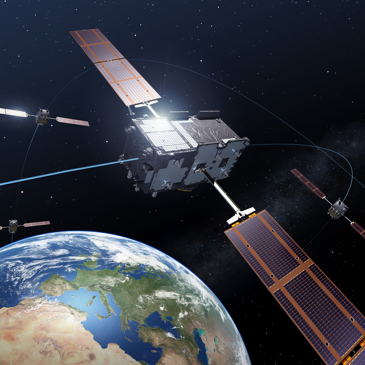
Galileo Accomplishes In-Orbit Validation
Nucleus of Four Now Operational: It “Works, and Works Well”
The European Space Agency (ESA) announced fulfillment of the in-orbit validation (IOV) of Galileo on February 10. IOV was achieved with four satellites, the minimum number needed to perform navigation fixes.
“IOV was required to demonstrate that the future performance that we want to meet when the system is deployed is effectively reachable,” said Sylvain Loddo, ESA’s Galileo Ground Segment manager. “It was an intermediate step with a reduced part of the system to effectively give evidence that we are on track.”
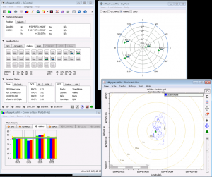
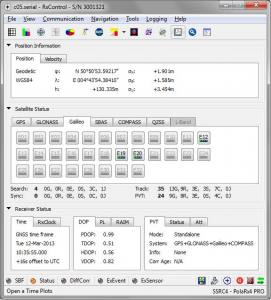
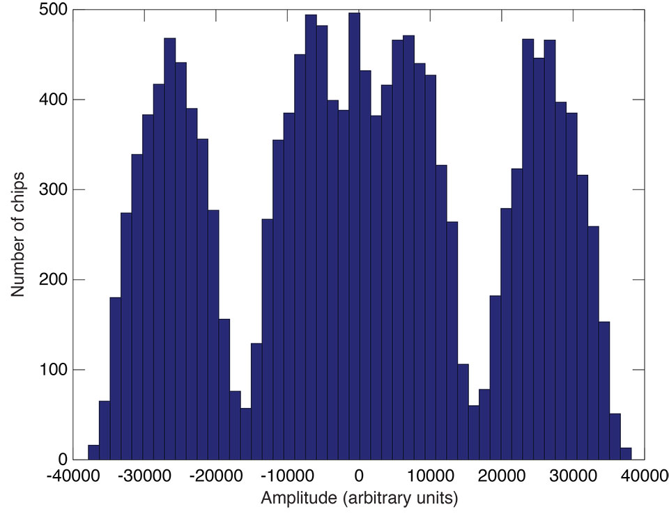
Following a March 2013 first determination of a ground location, jointly by Galileo’s space and ground segments, program managers undertook a wide variety of tests all across Europe.
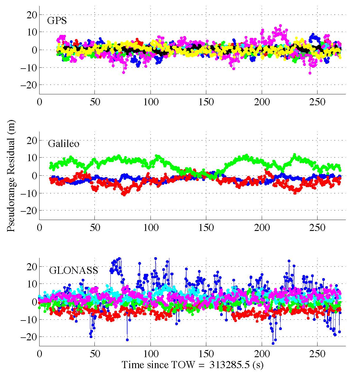
“More than 10,000 kilometers were driven by test vehicles in the process of picking up signals, along with pedestrian and fixed receiver testing. Many terabytes of IOV data were gathered in all,” said Marco Falcone, ESA’s Galileo System manager.
According to ESA’s elaboration on the test results, the system has proved itself capable of solely performing positioning fixes across the planet.
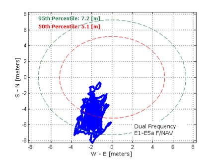
Galileo’s observed dual-frequency positioning accuracy is an average of 8 meters horizontal and 9 meters vertical, 95 percent of the time. Its average timing accuracy is 10 billionths of a second. Its performance is expected to improve as more satellites are launched and ground stations come on line.
For Galileo’s search-and-rescue function — operating as part of the existing international Cospas–Sarsat programme — 77 percent of simulated distress locations can be pinpointed within 2 kilometers, and 95 percent within 5 kilometers. All alerts are detected and forwarded to the Mission Control Centre within a minute and a half, compared to a design requirement of 10 minutes.
“Europe has proven with IOV that in terms of performance we are at a par with the best international systems of navigation in the world,” said Didier Faivre, ESA director of Galileo and Navigation-related Activities.
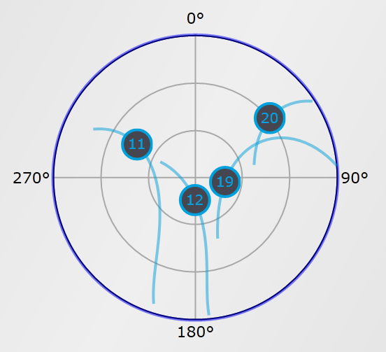
Historically Speaking. In a February 2013 GPS World article, Peter Steigenberger, Urs Hugentobler, and Oliver Montenbruck discussed Galileo-only positioning. “Using an ionosphere-free dual-frequency linear combination of pseudorange measurements on the Galileo E1 and E5a frequencies, the position of the TUME reference station [at the Technische Universität München (TUM) in Munich, Germany] could be determined with a 3D position error of less than 1.5 meters,’” the authors said.
Crystal Ball Gazing. The next two Galileo satellites, of the full operational capability (FOC) class, currently complete their testing for flight clearance at ESA’s ESTEC facility.
Six such satellites are destined to rise into space in 2014, according to ESA’s master plan. Should all those launches occur as scheduled, Galileo’s initial services could start by the end of the year.
GNSS Vulnerable: What to Do?
Too Much Sensitivity, Not Enough Robustness, Says Parkinson
Brad Parkinson, the founding architect of GPS, told a UK conference that the system needs to be made more robust to ensure worldwide availability of services to users. His concerns over GPS availability relate to threats such as the loss of authorized frequency spectrum (implicitly creating licensed jammers), space weather due to hyperactive ionospheric conditions, and deliberate or inadvertent jamming of GPS signals.
He warned that GPS is more vulnerable to sabotage or disruption than ever before, and charged that politicians and security chiefs are ignoring the risk. Western governments are “in their infancy in recognizing the problem,” he remarked further in an interview with London’s Financial Times. “[In the United States] I don’t know anyone that is really in charge of it. The Department of Homeland Security should be [but] … they don’t have any people that understand it very well. They’ve got one person without any budget to speak of.”
He also warned that Europe’s €5 billion Galileo system is equally at risk.
Parkinson proposed a three-stage program to:
- Protect (legally) the signal and physically eliminate jamming sources;
- Toughen the GPS/Galileo receiver’s resistance to interference;
- Augment the GPS signals with other satellites or with ground-based transmitters such as eLoran.
To support his proposal, Parkinson stated, “The number one need for all GPS or Galileo users is availability. Over the years, manufacturers of signal receiver technologies have focused too much on sensitivity and not enough on resilience or robustness. The maritime industry is a particular concern where users have taken GPS for granted. They must increase preparedness and backups as they do in aviation or other GNSS-using industries.
“Even today, most ships have only GPS and the vision of their crew to guide them when approaching harbors. As you can see from today’s conference, there are a wealth of solutions to toughen and back up GPS, many of which are not technologically difficult nor expensive, but still their adoption in sectors such as global shipping is certainly not adequate.”
As part of his protection program, Parkinson urged that penalties for jamming GPS networks be coordinated worldwide. “In Australia, if you cause interference likely to cause prejudice to the safe conduct of a vessel, it’s five years in the jug [jail] and $850,000.” Contrasting this with a U.S. case that may simply impose a forfeiture of the culprit’s jamming device, Parkinson added, “I’m calling for the community of nations to move to the Aussie-type penalties.”
In the toughening regard, Parkinson alluded to integration of GPS data with information derived from an inertial positioning system. “If you combine all of these things, a good set should be able to fly within 1 kilometer of a jammer with a 10-kilometer range,” said Parkinson. “That’s what I call toughening.”
Parkinson made his remarks as the keynote speech at GNSS Vulnerabilities and Resilient PNT 2014, hosted by the Royal Institute of Navigation. He will also deliver the keynote address, “Assured PNT: Assured World Economic Benefits,” for the European Navigation Conference on April 15 in The Netherlands.
GLONASS Seeks Broader Monitoring Footprint; Launch Imminent
Russia will deploy as many as seven ground monitoring and augmentation stations for GLONASS outside its national boundaries. GLONASS/GNSS Forum Association Executive Director Vladimir Klimov stated that “It is planned to deploy about six or seven stations on foreign territories this year.” Negotiations for the stations are now taking place with foreign nations.
Currently, there are 46 GLONASS ground stations on Russian territory, eight in neighboring countries, three in Antarctica, and one in Brazil. The United States recently spurned, with some Congressional trumpeting, a Russian tender to site one of the ground stations on U.S. soil.
New Instrument in Space. In mid-February, the most recent GLONASS-M satellite traveled to the Plesetsk cosmodrome for a probable mid-March launch. GLONASS-M 54 will carry a high-accuracy thermal stabilization unit, installed on the spacecraft for testing and flight qualification. The next-generation K-class of GLONASS spacecraft will loft this device to provide increased positioning accuracy.
Five GLONASS-M craft are planned for launch in 2014, in one triple and two single launches.